EP0477366A1 - Verfahren zum eingeben von lerndaten in einem visuell geführten system - Google Patents
Verfahren zum eingeben von lerndaten in einem visuell geführten system Download PDFInfo
- Publication number
- EP0477366A1 EP0477366A1 EP90902819A EP90902819A EP0477366A1 EP 0477366 A1 EP0477366 A1 EP 0477366A1 EP 90902819 A EP90902819 A EP 90902819A EP 90902819 A EP90902819 A EP 90902819A EP 0477366 A1 EP0477366 A1 EP 0477366A1
- Authority
- EP
- European Patent Office
- Prior art keywords
- values
- setting
- value
- optimum
- sensor system
- Prior art date
- Legal status (The legal status is an assumption and is not a legal conclusion. Google has not performed a legal analysis and makes no representation as to the accuracy of the status listed.)
- Granted
Links
Images

Classifications
-
- G—PHYSICS
- G05—CONTROLLING; REGULATING
- G05B—CONTROL OR REGULATING SYSTEMS IN GENERAL; FUNCTIONAL ELEMENTS OF SUCH SYSTEMS; MONITORING OR TESTING ARRANGEMENTS FOR SUCH SYSTEMS OR ELEMENTS
- G05B19/00—Programme-control systems
- G05B19/02—Programme-control systems electric
- G05B19/42—Recording and playback systems, i.e. in which the programme is recorded from a cycle of operations, e.g. the cycle of operations being manually controlled, after which this record is played back on the same machine
- G05B19/4202—Recording and playback systems, i.e. in which the programme is recorded from a cycle of operations, e.g. the cycle of operations being manually controlled, after which this record is played back on the same machine preparation of the programme medium using a drawing, a model
- G05B19/4207—Recording and playback systems, i.e. in which the programme is recorded from a cycle of operations, e.g. the cycle of operations being manually controlled, after which this record is played back on the same machine preparation of the programme medium using a drawing, a model in which a model is traced or scanned and corresponding data recorded
-
- G—PHYSICS
- G05—CONTROLLING; REGULATING
- G05B—CONTROL OR REGULATING SYSTEMS IN GENERAL; FUNCTIONAL ELEMENTS OF SUCH SYSTEMS; MONITORING OR TESTING ARRANGEMENTS FOR SUCH SYSTEMS OR ELEMENTS
- G05B19/00—Programme-control systems
- G05B19/02—Programme-control systems electric
- G05B19/42—Recording and playback systems, i.e. in which the programme is recorded from a cycle of operations, e.g. the cycle of operations being manually controlled, after which this record is played back on the same machine
Definitions
- the present invention relates to a taught data setting method in a visual sensor system, capable of automatically setting optimum taught data.
- a machine operating section e.g., a robot hand
- a machine operating section e.g., a robot hand
- an image of a single sample object is analyzed to prepare taught data (model) for image processing, which is to be supplied beforehand to a visual sensor.
- the taught data is compared with an image (scene) of the work object photographed by a camera of the visual sensor system.
- a manual modification of the taught data is carried out in a trial-and-error manner, so long as instability is found in the work object recognition based on the taught data. This taught data modification requires skill and labor.
- the object of the present invention is to provide a taught data setting method in a visual sensor system, which is capable of automatically setting optimum taught data.
- a taught data setting method of the present invention comprises the steps of: (a) storing a plurality of sample images; (b) determining formal setting values of taught data on the basis of one of the plurality of sample images; (c) detecting and setting feature data, which specifies a position of each of the plurality of sample images, from each sample image by using the formal setting values; (d) detecting the respective feature data of the plurality of sample images while changing at least one of the formal setting values; and (e) automatically determining values of the taught data enough to minimize an error between each of the detected feature data and a corresponding one of the set feature data, and automatically setting the determined values as optimum values of the taught data.
- the feature data of each sample image specifying the position of each of the plurality of sample images is detected and set by using the formal setting values determined on the basis of a single sample image, and the values of the taught data enough to minimize the errors between the feature data of the respective sample images, detected while changing the at least one formal setting value, and the corresponding ones of the aforesaid set feature data are automatically set as the optimum values of taught data. Accordingly, the optimum taught data can be set rapidly, without the need of intervention of a skilled operator.
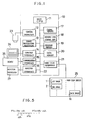
- a visual sensor system to which a taught data setting method according to an embodiment of the present invention is applied comprises an image central processing device 10.
- This processing device 10 comprises a main central processing unit (hereinafter referred to as main CPU) 11, a camera interface 12, an image processing processor 13, a console interface 14, a communication interface 15, a monitor interface 16, and a frame memory 17. Further, the device 10 comprises a memory 18, comprised of a ROM, for storage of control software, a program memory 19 comprised of a RAM, and a hard disk interface 21. These elements 12 to 21 are connected to the main CPU 11 through busses 20.
- a camera 23 for photographing objects is connected to the camera interface 12.
- An image from the camera 23 is supplied to the camera interface 12 in which the image is subjected to an A/D conversion, to be converted into a gray scale image consisting of 256 X 256 picture elements each of which is represented by 1 byte, and the gray scale image is stored in the frame memory 17.
- the gray scale image is subjected to image processing in the image processing processor 13 for identification of the object and for detection of the position and orientation of the object.
- the resultant taught data and the like are stored in the data memory 20.
- a hard disk device 25 connected to the hard disk interface 21 comprises a hard disk whose capacity is 20 megabytes for storage of approximately 320 images.
- a console 24 Connected to the console interface 14 is a console 24 which comprises various kinds of keys, including numeric keys, for input of various commands and for input, edit, registration, execution, etc., of an application program, and a liquid crystal display for displaying various work menus, a program list, etc.
- a machine e.g., a robot 26, on which the visual sensor system is mounted, and a monitor television 27 for displaying the image photographed by the camera 23 are connected to the communication interface 15 and the monitor interface 16, respectively.
- the control software memory 18 is arranged to store a program for visual sensor system control
- the program memory 19 is arranged to store a user program which is prepared by operator's operations in accordance with a menus displayed on the console 24.
- sample objects e.g., N sample objects (not shown) are photographed in sequence by the camera 23, preferably, at the same photograph position.
- these samples are arbitrarily extracted from a large number of circular objects of the same kind.
- the samples have variations in their sizes, shapes, etc.
- the gray scale images 1 to N are stored in the frame memory 17. Thereafter, the sample images 1 to N are sequentially transferred to and stored in the hard disk of the hard disk device 25.
- an arbitrary one of the sample images 1 to N is read out from the hard disk, to be stored in the frame memory 17.
- This single sample image is subjected to image processing in the image processing processor 13, so that values P10 to P60 of first to sixth parameters P1 to P6 for image processing are detected from the single sample image, as taught data with respect to the circular object.
- the detected values P10 to P60 are stored in the data memory 20, as formal setting values of the taught data.
- the first to fourth parameters P1 to P4 are the diameter, circumference, area, deformation degree (area/square of circumference) of the circle, respectively.
- the fifth and sixth parameters P5 and P6 are a type of a smoother filter for improving flicker developed on the screen, and a type of an emphasizing filter for improving obscurity of the screen image, respectively.
- the sample images 1 to N which are sequentially transferred from the hard disk to the frame memory 17, are sequentially subjected to image processing with the use of the formal setting values P10 to P60, and feature data (in the present embodiment, the center positions C10 to CN0 of the images) specifying positions of the respective sample images are detected in sequence.
- feature data in the present embodiment, the center positions C10 to CN0 of the images
- the operator Upon detection of the image center positions, the operator manually corrects a dislocation of the image center position, where required, with reference to the sample image concerned which is displayed on the monitor television 27, and manually sets the corrected center position of the image.
- the thus detected and set image center positions C10 to CN0 of the sample images 1 to N are stored in the data memory 20.
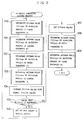
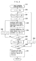
- the main CPU 11 executes a first parameter adjusting process of Fig. 3, which corresponds to the step 100 of a main routine shown in Fig. 2.
- the CPU performs image processing of the first image by the use of the first parameter value P(-M1) and the formal setting values P20 to P40 of the second to fourth parameters, to thereby detect the image center position C1(-M1).
- the CPU calculates the square E1(1), generally, Ei(j), of the error between the image center position C1(-M1) and a corresponding image center position Cj0 set in the data memory 20 (step 204).
- the value Ei(j) is calculated by deriving the sum of the square of the error between X-axis positions of the image centers Cj(i) and Cjo in the sensor coordinate system and the square of the error between Y-axis positions of these centers.
- step 205 the CPU determines whether the index j is equal to the total number N of the sample images.
- the determination result is negative.
- the CPU 11 determines the total sum P1E(-M1) of these calculated values, generally, P1E(i), and causes the program memory 19 to store the total sum (step 207). Further, at step 208 following step 207, the CPU determines whether the index i is equal to or larger than its maximum value of +M1.
- the index i is equal to or larger than the maximum value +M1, i.e., when it is determined that values of P1E(-M1), P1E(-M1+1), ---, P1E(+M1), each representing a corresponding one of the total sums of the squares of the errors between the detected image center positions of the sample images 1 to N and the set image center positions thereof, have been calculated with regard to respective values of the first parameter P1, which changes at intervals of ⁇ l1 within a region (Fig.
- step 210 the CPU 11 determines the minimum value P1E(i)min of these calculated values. Then, the CPU finds that value of the first parameter P1 which-provides the aforesaid minimum value, and causes the same to be stored in the program memory 19, as the optimum value P1(i)opt of the first parameter (step 210), whereby the sub-routine process of Fig. 3 is finished. Then, step 101 of the main-routine of Fig. 2 is entered.
- step 101 for determining an optimum value of the second parameter is substantially the same as those in Fig. 3. Namely, the first parameter is fixed to the optimum value of P1(i)opt, while the third and fourth parameters are fixed to the formal setting values P30 and P40, respectively.
- values of P2E(-M2), P2E(-M2+1), ---, P2E(+M2) are determined, each indicating the total sum of the squares of the errors between detected center positions and the set center positions C10 to CN0 of the respective sample images, while changing a value of the second parameter P2 at interval ⁇ l2, which is the same as or different from the aforesaid interval ⁇ l1, within a region P20-M2 ⁇ l2 - P20+M2 ⁇ l2 (not shown), which is the same as or different from the the aforesaid region P10-M1 ⁇ l1-P10+M1 ⁇ l1.
- the optimum value P2(i)opt of the second parameter which provides the minimum value P2E(i)min of these calculated values is determined and stored.
- the third parameter is changed, while the first, second and fourth parameters are fixed to the optimum values P1(i) opt, P2(i)opt and the formal setting value P40, respectively.
- the CPU determines an optimum value P3(i)opt of the third parameter which provides the minimum value of the total sums of the squares of the errors between image center positions which are respectively determined under the above-mentioned conditions.
- an optimum value P4 of the fourth parameter is determined, with the first to third parameters respectively fixed to the optimum values P1(i)opt to P3(i)opt.
- the CPU 11 compares each of the optimum values P1(i)opt to P4(i)opt of the first to fourth parameters with a corresponding one of the formal setting values P10 to P40 (step 104), and determines whether the error between each of the optimum values and an associated one of the formal setting values is equal to or larger than an allowable value (step 105). If any one of the errors is equal to or larger than the allowable value, the optimum values are respectively set as the initial values (step 106), and executes steps 100 to 106 again. On the other hand, if each error is less than the allowable value, the optimum values are substituted for the formal setting values in the data memory 20, respectively (step 107).
- the fifth parameter assumes a value of P5(0) indicating that no smoother filter is required, no pre-processing is performed.
- the first sample image is then subjected to image processing which utilizes the optimum values of the first to fourth parameters, generally after completion of the pre-processing by the smoother filter, so as to detect the center position C1(0) Of the first sample image, generally, the center position Cj(i) of the j-th image (step 302).
- the CPU derives the square E0(1) of the error between a detected center position C1(0) and the set center position C10, generally, Ei(j), and renews a value of the index j by adding "1" thereto (step 304), and further determines whether the index j is larger than the total number N of the sample images (step 305).
- the CPU executes steps 302 to 305 again, to derive a value of E0(2).
- the CPU 11 calculates the sum P5E(0) of these calculated values, generally, the sum P5E(i), and causes the program 19 to store the calculated sum (step 306). Then, the CPU renews a value of the index i by adding "1" thereto (step 307), and determines whether the index value is larger than the total number M5 of types of the smoother filter (step 308).
- the CPU executes steps 301 to 308 again, to calculate and store the sum P5E(1) for a case where a first smoother filter is employed.
- the CPU 11 determines the minimum value P5E(i)min of these calculated values, and causes the data memory 20 to store an optimum value P5(i)opt of the fifth parameter, which value corresponds to that index value providing the aforementioned minimum value and which indicates the kind of an optimum smoother filter (step 309), whereby the processing of Fig. 4 is completed and step 109 of the main routine is entered.
- Processing procedures in step 109 for adjustment processing of the sixth parameter are substantially the same as those in Fig. 2, except in that a total number M6 (not shown) of kinds of the emphasize filter, which is the same as or different from the total number M5 of the smoother filter types, is utilized in place of the value M5.
- the embodiment includes steps 104 to 106 to restart the parameter adjustment process using the optimum values of the first to fourth parameters as the initial values thereof when any one of the errors between the optimum values and the formal setting values of the first to fourth parameters is equal to or larger than the allowable value.
- steps 104 to 106 to restart the parameter adjustment process using the optimum values of the first to fourth parameters as the initial values thereof when any one of the errors between the optimum values and the formal setting values of the first to fourth parameters is equal to or larger than the allowable value.
- these steps may be omitted if the stability in detecting the object is attained by performing the parameter adjustment once.
- an external memory for sample image storage is comprised of the hard disk.
- other kinds of memories such as a floppy disk may be employed.
Landscapes
- Physics & Mathematics (AREA)
- General Physics & Mathematics (AREA)
- Engineering & Computer Science (AREA)
- Automation & Control Theory (AREA)
- Image Analysis (AREA)
- Image Processing (AREA)
- Length Measuring Devices By Optical Means (AREA)
- Manipulator (AREA)
- Image Input (AREA)
- Geophysics And Detection Of Objects (AREA)
- Closed-Circuit Television Systems (AREA)
- Control Of Position Or Direction (AREA)
Applications Claiming Priority (3)
| Application Number | Priority Date | Filing Date | Title |
|---|---|---|---|
| JP1029735A JPH02210584A (ja) | 1989-02-10 | 1989-02-10 | 視覚センサにおける画像処理用教示データ設定方法及び視覚センサ |
| JP129735/89 | 1989-02-10 | ||
| PCT/JP1990/000165 WO1990009627A1 (fr) | 1989-02-10 | 1990-02-09 | Procede de reglage de donnees d'apprentissage dans un systeme de detection visuelle |
Publications (3)
| Publication Number | Publication Date |
|---|---|
| EP0477366A1 true EP0477366A1 (de) | 1992-04-01 |
| EP0477366A4 EP0477366A4 (en) | 1993-02-03 |
| EP0477366B1 EP0477366B1 (de) | 1996-12-27 |
Family
ID=12284363
Family Applications (1)
| Application Number | Title | Priority Date | Filing Date |
|---|---|---|---|
| EP90902819A Expired - Lifetime EP0477366B1 (de) | 1989-02-10 | 1990-02-09 | Verfahren zum eingeben von lerndaten in einem visuell geführten system |
Country Status (4)
| Country | Link |
|---|---|
| EP (1) | EP0477366B1 (de) |
| JP (1) | JPH02210584A (de) |
| DE (1) | DE69029519T2 (de) |
| WO (1) | WO1990009627A1 (de) |
Families Citing this family (3)
| Publication number | Priority date | Publication date | Assignee | Title |
|---|---|---|---|---|
| US6548296B1 (en) | 1997-07-23 | 2003-04-15 | Roche Diagnostics Gmbh | Methods for identifying human cell lines useful for endogenous gene activation, isolated human lines identified thereby, and uses thereof |
| TW202235239A (zh) * | 2020-11-18 | 2022-09-16 | 日商發那科股份有限公司 | 調整參數的裝置、機器人系統、方法及電腦程式 |
| CN113887534B (zh) * | 2021-12-03 | 2022-03-18 | 腾讯科技(深圳)有限公司 | 一种对象检测模型的确定方法和相关装置 |
Family Cites Families (4)
| Publication number | Priority date | Publication date | Assignee | Title |
|---|---|---|---|---|
| JPH0612484B2 (ja) * | 1982-02-18 | 1994-02-16 | 株式会社東芝 | 自動溶接方法 |
| JPS60200385A (ja) * | 1984-03-26 | 1985-10-09 | Hitachi Ltd | 姿勢判定方式 |
| JPH07107651B2 (ja) * | 1986-02-05 | 1995-11-15 | オムロン株式会社 | 自動検査装置における基準基板デ−タの教示方法 |
| JPH07107650B2 (ja) * | 1986-02-05 | 1995-11-15 | オムロン株式会社 | 自動検査装置における基準基板デ−タの教示方法 |
-
1989
- 1989-02-10 JP JP1029735A patent/JPH02210584A/ja active Pending
-
1990
- 1990-02-09 WO PCT/JP1990/000165 patent/WO1990009627A1/ja not_active Ceased
- 1990-02-09 DE DE69029519T patent/DE69029519T2/de not_active Expired - Fee Related
- 1990-02-09 EP EP90902819A patent/EP0477366B1/de not_active Expired - Lifetime
Also Published As
| Publication number | Publication date |
|---|---|
| DE69029519D1 (de) | 1997-02-06 |
| EP0477366B1 (de) | 1996-12-27 |
| DE69029519T2 (de) | 1997-04-10 |
| JPH02210584A (ja) | 1990-08-21 |
| EP0477366A4 (en) | 1993-02-03 |
| WO1990009627A1 (fr) | 1990-08-23 |
Similar Documents
| Publication | Publication Date | Title |
|---|---|---|
| JP3394278B2 (ja) | 視覚センサ座標系設定治具及び設定方法 | |
| US5471312A (en) | Automatic calibration method | |
| JP3394322B2 (ja) | 視覚センサを用いた座標系設定方法 | |
| US5194792A (en) | Tool center point setting method in a robot | |
| CN115066313B (zh) | 用于加工装置的工件的安装方法、工件安装支援系统及存储介质 | |
| US5066902A (en) | Automatic nominal data setting method in a visual sensor system | |
| US5566247A (en) | Taught data setting method in a visual sensor system | |
| EP0477366B1 (de) | Verfahren zum eingeben von lerndaten in einem visuell geführten system | |
| DE112021000229T5 (de) | Roboter-System | |
| CN120198858B (zh) | 一种用于智能制造生产线的批量图像数据处理方法及系统 | |
| JPH056214A (ja) | ロボツトの教示方法 | |
| CN113119087B (zh) | 壳管胀接控制方法、系统和存储介质 | |
| CN119078276B (zh) | 一种精装盒自动化生产方法及其系统 | |
| JPH0299802A (ja) | ハンドアイを用いた視覚センサにおける座標系設定方法 | |
| EP0708392A1 (de) | Operationelles Führungssystem für eine Messmaschine | |
| JPH0535323A (ja) | Nc装置 | |
| JPH06160022A (ja) | 画像位置補正装置 | |
| JPH1058363A (ja) | ロボットのオフライン教示装置 | |
| JPH02276901A (ja) | 視覚センサの位置ズレ修正方法 | |
| CN112184819A (zh) | 机器人的引导方法、装置、计算机设备和存储介质 | |
| JPH01147676A (ja) | ウィンドウの制御方法 | |
| CN120219768B (zh) | 一种用于流水线产品的参数自动化确定方法及系统 | |
| JPH05127715A (ja) | 視覚センサにおける検出プログラム自動調整方法 | |
| JPS6380306A (ja) | ワークにおける基準穴の重心決定方法 | |
| CN113160187B (zh) | 一种设备的故障检测方法及装置 |
Legal Events
| Date | Code | Title | Description |
|---|---|---|---|
| PUAI | Public reference made under article 153(3) epc to a published international application that has entered the european phase |
Free format text: ORIGINAL CODE: 0009012 |
|
| 17P | Request for examination filed |
Effective date: 19900912 |
|
| AK | Designated contracting states |
Kind code of ref document: A1 Designated state(s): DE FR GB |
|
| A4 | Supplementary search report drawn up and despatched | ||
| AK | Designated contracting states |
Kind code of ref document: A4 Designated state(s): DE FR GB |
|
| 17Q | First examination report despatched |
Effective date: 19941219 |
|
| GRAG | Despatch of communication of intention to grant |
Free format text: ORIGINAL CODE: EPIDOS AGRA |
|
| GRAH | Despatch of communication of intention to grant a patent |
Free format text: ORIGINAL CODE: EPIDOS IGRA |
|
| GRAH | Despatch of communication of intention to grant a patent |
Free format text: ORIGINAL CODE: EPIDOS IGRA |
|
| GRAA | (expected) grant |
Free format text: ORIGINAL CODE: 0009210 |
|
| AK | Designated contracting states |
Kind code of ref document: B1 Designated state(s): DE FR GB |
|
| REF | Corresponds to: |
Ref document number: 69029519 Country of ref document: DE Date of ref document: 19970206 |
|
| PG25 | Lapsed in a contracting state [announced via postgrant information from national office to epo] |
Ref country code: GB Effective date: 19970327 |
|
| ET | Fr: translation filed | ||
| PG25 | Lapsed in a contracting state [announced via postgrant information from national office to epo] |
Ref country code: FR Effective date: 19971030 |
|
| PLBE | No opposition filed within time limit |
Free format text: ORIGINAL CODE: 0009261 |
|
| STAA | Information on the status of an ep patent application or granted ep patent |
Free format text: STATUS: NO OPPOSITION FILED WITHIN TIME LIMIT |
|
| GBPC | Gb: european patent ceased through non-payment of renewal fee |
Effective date: 19970327 |
|
| 26N | No opposition filed | ||
| REG | Reference to a national code |
Ref country code: FR Ref legal event code: ST |
|
| PGFP | Annual fee paid to national office [announced via postgrant information from national office to epo] |
Ref country code: DE Payment date: 19990212 Year of fee payment: 10 |
|
| PG25 | Lapsed in a contracting state [announced via postgrant information from national office to epo] |
Ref country code: DE Free format text: LAPSE BECAUSE OF NON-PAYMENT OF DUE FEES Effective date: 20001201 |