EP0477116B2 - Boiler with reinforced intermediate elements - Google Patents
Boiler with reinforced intermediate elements Download PDFInfo
- Publication number
- EP0477116B2 EP0477116B2 EP19910440074 EP91440074A EP0477116B2 EP 0477116 B2 EP0477116 B2 EP 0477116B2 EP 19910440074 EP19910440074 EP 19910440074 EP 91440074 A EP91440074 A EP 91440074A EP 0477116 B2 EP0477116 B2 EP 0477116B2
- Authority
- EP
- European Patent Office
- Prior art keywords
- boiler
- water
- exchange
- firebox
- combustion chamber
- Prior art date
- Legal status (The legal status is an assumption and is not a legal conclusion. Google has not performed a legal analysis and makes no representation as to the accuracy of the status listed.)
- Expired - Lifetime
Links
- 238000002485 combustion reaction Methods 0.000 claims description 23
- XLYOFNOQVPJJNP-UHFFFAOYSA-N water Substances O XLYOFNOQVPJJNP-UHFFFAOYSA-N 0.000 claims description 23
- 206010022000 influenza Diseases 0.000 claims description 9
- 239000003517 fume Substances 0.000 claims description 5
- 239000000567 combustion gas Substances 0.000 claims description 4
- 229910001018 Cast iron Inorganic materials 0.000 claims description 3
- 239000007789 gas Substances 0.000 claims description 3
- 238000009423 ventilation Methods 0.000 claims 1
- 239000000543 intermediate Substances 0.000 description 10
- 238000010438 heat treatment Methods 0.000 description 2
- 210000002445 nipple Anatomy 0.000 description 2
- 208000018672 Dilatation Diseases 0.000 description 1
- XEEYBQQBJWHFJM-UHFFFAOYSA-N Iron Chemical compound [Fe] XEEYBQQBJWHFJM-UHFFFAOYSA-N 0.000 description 1
- 241001080024 Telles Species 0.000 description 1
- 230000006978 adaptation Effects 0.000 description 1
- 230000003416 augmentation Effects 0.000 description 1
- 238000010276 construction Methods 0.000 description 1
- 239000000463 material Substances 0.000 description 1
- 238000000034 method Methods 0.000 description 1
- 230000000135 prohibitive effect Effects 0.000 description 1
- 230000035939 shock Effects 0.000 description 1
- 239000000779 smoke Substances 0.000 description 1
Images

Classifications
-
- F—MECHANICAL ENGINEERING; LIGHTING; HEATING; WEAPONS; BLASTING
- F24—HEATING; RANGES; VENTILATING
- F24H—FLUID HEATERS, e.g. WATER OR AIR HEATERS, HAVING HEAT-GENERATING MEANS, e.g. HEAT PUMPS, IN GENERAL
- F24H1/00—Water heaters, e.g. boilers, continuous-flow heaters or water-storage heaters
- F24H1/22—Water heaters other than continuous-flow or water-storage heaters, e.g. water heaters for central heating
- F24H1/24—Water heaters other than continuous-flow or water-storage heaters, e.g. water heaters for central heating with water mantle surrounding the combustion chamber or chambers
- F24H1/30—Water heaters other than continuous-flow or water-storage heaters, e.g. water heaters for central heating with water mantle surrounding the combustion chamber or chambers the water mantle being built up from sections
- F24H1/32—Water heaters other than continuous-flow or water-storage heaters, e.g. water heaters for central heating with water mantle surrounding the combustion chamber or chambers the water mantle being built up from sections with vertical sections arranged side by side
Definitions
- the present invention relates to a boiler improved cast iron element type comprising at least one intermediate element reinforced heat exchanger with surfaces additional exchange.
- each intermediate element reinforced exchanger passes through the combustion chamber.
- the invention also relates to such an intermediate element reinforced heat exchanger for boilers in medium and high power cast iron in the area of domestic, collective heating and semi-industrial.
- the boilers covered by the invention are made up of a horizontal succession of elements exchangers assembled together by juxtaposition horizontal using tie rods and nipples.
- This invention does not provide any structure of exchange leading the water and crossing the room combustion.
- the length of the combustion chamber such boilers increases rapidly from a certain power. This augmentation is so fast that the combustion chamber quickly becomes noticeably longer than the flame or exceeds the standard lengths.
- Figure 2 shows the principle of constitution of the improved boiler according to the invention.
- Said boiler is conventionally formed a front facade element 1 on which is mounted a burner 2, for example with supply air, of a rear panel element 3 and heat exchanger elements simple intermediates such as 4 or reinforced 5, the assembly being assembled by nipples and horizontal tie rods.
- the exchanger elements 4 and 5 have at upper part of flues such as 6, with spikes or with fins, arranged symmetrically in several horizontal floors.
- first group 7 along which combustion gases and fumes are evacuated towards the front of the boiler, along a route horizontal go A, by a compartment of return 8 from the back cover, then evacuated to the rear, along a horizontal return path B, the along a second group 9 of several floors of flues by a collector 10 of front facade.
- the exchanger elements 4 and 5 have in their second half a passage from flame, respectively 11 and 12, completely free for the first or occupied by items additional exchange which will be discussed below for the latter.
- the burner projects a developing flame 13 along a combustion chamber 14. formed by the succession of flame passages 11 and 12 of the different intermediate exchangers simple then reinforced delimiting a first part 15 then a second part 16.
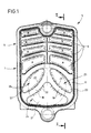
- the original feature of this boiler is located at the level of the intermediate elements reinforced 5 of which one is shown in detail on the figure 1.
- These reinforced intermediate elements are made up so that after assembly, the second part 16 of the combustion chamber 14 is fitted with exchange surfaces additional, formed by the presence of a group of additional water channels crossing the passage of flame and communicating with the envelope 17 of water circulation surrounding said combustion chamber.
- the chamber combustion 14 consists of the first classic part 15 in fully open space and the second part 16 partially closed transversely by the succession of water arms 18 and 19 of the reinforced exchangers 5 juxtaposed.
- the hot gases and smoke return to the front of the boiler along the flues A and are directed to the outlet of gases and fumes from combustion in the upper part of the rear panel 3 by the upper flues B arranged on several horizontal floors.
Description
La présente invention se rapporte à une chaudière améliorée en fonte du type par éléments comportant au moins un élément intermédiaire échangeur de chaleur renforcé présentant des surfaces supplémentaires d'échange.The present invention relates to a boiler improved cast iron element type comprising at least one intermediate element reinforced heat exchanger with surfaces additional exchange.
Plus particulièrement, les surfaces supplémentaires d'échange de chaque élément intermédiaire échangeur renforcé traversent la chambre de combustion.More specifically, the additional areas exchange of each intermediate element reinforced exchanger pass through the combustion chamber.
L'invention concerne aussi un tel élément intermédiaire échangeur de chaleur renforcé pour chaudières en fonte de moyenne et grande puissance dans le domaine du chauffage domestique, collectif et semi-industriel.The invention also relates to such an intermediate element reinforced heat exchanger for boilers in medium and high power cast iron in the area of domestic, collective heating and semi-industrial.
Les chaudières visées par l'invention sont constituées d'une succession horizontale d'éléments échangeurs assemblés entre eux par juxtaposition horizontale à l'aide de tirants et de nipples.The boilers covered by the invention are made up of a horizontal succession of elements exchangers assembled together by juxtaposition horizontal using tie rods and nipples.
On connaít l'invention décrite dans le brevet français FR-A-2.071.754 au nom de BUDERUS qui se rapporte à une chaudière de chauffage formée d'éléments échangeurs juxtaposes.We know the invention described in the patent French FR-A-2,071,754 in the name of BUDERUS which refers to a formed heating boiler juxtaposed exchanger elements.
Ces éléments échangeurs comportent classiquement des carneaux verticaux qui relient le foyer à des canaux collecteurs supérieurs. La seule particularité de cette chaudière concerne la présence de nervures directrices sensiblement verticales disposées sur ou conformées dans les surfaces d'échange thermique ainsi que des chicanes horizontales prévues sur celles-ci à des hauteurs différentes.These exchanger elements conventionally comprise vertical flues that connect the fireplace to upper collector channels. The only peculiarity of this boiler concerns the presence substantially vertical guide ribs arranged on or conformed in surfaces heat exchange as well as horizontal baffles provided on them at different heights.
Cette invention ne prévoit aucune structure d'échange conduisant l'eau et traversant la chambre de combustion.This invention does not provide any structure of exchange leading the water and crossing the room combustion.
Ainsi, si les nervures et chicanes existant sur les éléments échangeurs de cette invention apportent bien un supplément de rendement, celui-ci est limité et un certain espace de la chambre de combustion reste inutilisé.So if the ribs and baffles existing on the exchanger elements of this invention provide well an extra yield, this one is limited and some room space from combustion remains unused.
Pour des raisons de construction, de taille et de rendement ou de performances des éléments échangeurs, la longueur de la chambre de combustion de telles chaudières augmente rapidement à partir d'une certaine puissance. Cette augmentation est si rapide que la chambre de combustion devient vite notablement plus longue que la flamme ou dépasse les longueurs normalisées.For reasons of construction, size and performance or element performance exchangers, the length of the combustion chamber such boilers increases rapidly from a certain power. This augmentation is so fast that the combustion chamber quickly becomes noticeably longer than the flame or exceeds the standard lengths.
Dans ces conditions, les chaudières ne fonctionnent pas dans des conditions optimales et présentent des longueurs prohibitives peu compatibles avec la recherche actuelle de compacité pour les chaufferies.In these conditions, the boilers do not work not in optimal conditions and present prohibitive lengths that are hardly compatible with the current compactness research for boiler rooms.
Les problèmes sont résolus pour la chaudière selon la revendication 1.Problems are solved for the boiler according to claim 1.
Les caractéristiques techniques et d'autres avantages de l'invention sont consignés dans la description qui suit, effectuée à titre d'exemple non limitatif sur un mode d'exécution en référence aux dessins accompagnants dans lesquels :
- la figure 1 est une vue en élévation de l'élément échangeur intermédiaire renforcé équipant la chaudière selon l'invention ;
- la figure 2 est une vue schématique en coupe verticale selon la ligne II - II de la figure 1 d'une telle chaudière montrant l'emplacement des éléments échangeurs intermédiaires et la circulation des gaz et fumées de combustion.
- Figure 1 is an elevational view of the reinforced intermediate exchanger element fitted to the boiler according to the invention;
- Figure 2 is a schematic view in vertical section along line II - II of Figure 1 of such a boiler showing the location of the intermediate exchanger elements and the circulation of combustion gases and fumes.
De nombreux avantages découlent de la présente invention tels que ceux mentionnés ci-après :
- à puissance égale, elle permet de diminuer notablement le poids et le prix de revient final par un gain substantiel en matière, une réduction du temps de montage et un coût plus faible de transport ;
- la réduction de dimension des carneaux permet de diminuer la hauteur totale ;
- on peut augmenter la puissance totale de la chaudière tout en gardant son même encombrement en longueur ;
- la courbure inverse des bras d'eau permet de dégager des sections de passage suffisantes à un bon échange thermique dans le haut de la chambre de combustion et apporte une meilleure tenue aux dilatations et aux chocs thermiques.
- at equal power, it makes it possible to significantly reduce the weight and the final cost price by a substantial saving in material, a reduction in assembly time and a lower transport cost;
- reducing the size of the flues reduces the total height;
- it is possible to increase the total power of the boiler while keeping its same overall dimensions;
- the reverse curvature of the water arms allows clear passage sections sufficient for good heat exchange at the top of the combustion chamber and provides better resistance to expansion and thermal shock.
On se reportera d'abord à la figure 2 qui montre le principe de constitution de la chaudière améliorée selon l'invention.We will first refer to Figure 2 which shows the principle of constitution of the improved boiler according to the invention.
Ladite chaudière est formée de façon classique
d'un élément de façade avant 1 sur lequel est
monté un brûleur 2, par exemple à air soufflé, d'un
élément de façade arrière 3 et d'éléments échangeurs
intermédiaires simples tels que 4 ou renforcés
5, l'ensemble étant assemblé par des nipples
et des tirants horizontaux.Said boiler is conventionally formed
a front facade element 1 on which is
mounted a
Les éléments échangeurs 4 et 5 présentent en
partie supérieure des carneaux tels que 6, à picots
ou à ailettes, disposés symétriquement en plusieurs
étages horizontaux.The
On distingue un premier groupe 7 le long duquel
les gaz et fumées de combustion sont évacués
vers l'avant de la chaudière, selon un parcours
horizontal aller A, par un compartiment de
renvoi 8 de la façade arrière, puis évacués vers
l'arrière, selon un parcours horizontal retour B, le
long d'un deuxième groupe 9 de plusieurs étages
de carneaux par un collecteur 10 de façade avant.There is a
Les éléments échangeurs 4 et 5 présentent
dans leur deuxième demi-partie un passage de
flamme, respectivement 11 et 12, entièrement libre
pour les premiers ou occupé par des éléments
supplémentaires d'échange dont il sera question ci-après
pour les seconds. The
Le brûleur projette une flamme 13 qui se développe
le long d'une chambre de combustion 14.
formée par la succession des passages de flammes
11 et 12 des différents échangeurs intermédiaires
simples puis renforcés délimitant une première
partie 15 puis une deuxième partie 16.The burner projects a developing flame 13
along a
La caractéristique originale de cette chaudière
se situe au niveau des éléments intermédiaires
renforcés 5 dont l'un est représenté en détail sur la
figure 1. Ces éléments intermédiaires renforcés
sont constitués de telle sorte qu'après assemblage,
la deuxième partie 16 de la chambre de combustion
14 se trouve équipée de surfaces d'échange
supplémentaires, formées par la présence d'un
groupe de canaux d'eau supplémentaires traversant
le passage de flamme et communiquant avec
l'enveloppe 17 de circulation d'eau entourant ladite
chambre de combustion.The original feature of this boiler
is located at the level of the intermediate elements
reinforced 5 of which one is shown in detail on the
figure 1. These reinforced intermediate elements
are made up so that after assembly,
the
Il s'agit de canaux sous la forme d'au moins
deux bras d'eau 18 et 19 symétriques réunis entre
eux en partie centrale supérieure Ils communiquent
avec l'enveloppe 17 de circulation d'eau, d'une part
en partie centrale supérieure de la chambre de
combustion 14, et d'autre part sur les parties latérales
inférieures de ladite chambre. Afin d'améliorer
l'échange, les surfaces extérieures des parois
des bras d'eau 18 et 19 sont pourvues de façon
classique de picots ou d'ailettes 20 favorisant
l'échange thermique.These are channels in the form of at least
two
Ces bras d'eau 18 et 19 délimitent dans la
section du passage de flamme de chaque élément
intermédiaire renforcé 5 des secteurs adjacents à
section en contours curvilignes et à forme générale
triangulaire et oblongue, tels qu'un secteur principal
inférieur 21 et adjacents supérieurs 22 et 23.
Ces secteurs constituent par juxtaposition des éléments
échangeurs intermédiaires renforcés trois
canaux aérauliques distincts 24, 25 et 26 le long
desquels est projetée, divisée et évacuée la projection
aéraulique de la flamme.These
Ces bras d'eau 18 et 19 concourent à un
double résultat : augmenter sensiblement les surfaces
d'échange d'une part et diminuer corrélativement
la longueur de la chambre de combustion 14
pour rendre, à puissance égale, la chaudière notablement
plus compacte.These
Comme on peut le remarquer sur la figure 1, la concavité de ces bras d'eau est dirigée vers le haut, contrairement aux enseignements de la technique antérieure et aux habitudes professionnelles qui recherchaient et recommandaient l'adoption d'une concavité inverse. Celle-ci correspondait à deux buts principaux : d'une part favoriser le tirage thermique de l'eau et d'autre part dégager le plus possible la chambre de combustion qui devait impérativement rester un espace entièrement ouvert sans aucun élément transversal.As can be seen in Figure 1, the concavity of these water arms is directed towards the high, contrary to the teachings of the technique previous and professional habits who sought and recommended adoption of a reverse concavity. This corresponded to two main goals: on the one hand to favor the drawing thermal of the water and on the other hand give off the most possible the combustion chamber which had imperatively remain a fully open space without any transverse element.
Après assemblage de la chaudière, la chambre
de combustion 14 se compose de la première
partie classique 15 en espace entièrement ouvert
et de la seconde partie 16 partiellement obturée
transversalement par la succession des bras d'eau
18 et 19 des échangeurs renforcés 5 juxtaposés.After assembling the boiler, the
Les gaz chauds et fumées reviennent vers
l'avant de la chaudière le long des carneaux A et
sont dirigés vers la sortie des gaz et fumées de
combustion en partie haute de la façade arrière 3
par les carneaux supérieurs B disposés sur plusieurs
étages horizontaux.The hot gases and smoke return to
the front of the boiler along the flues A and
are directed to the outlet of gases and fumes from
combustion in the upper part of the
Bien entendu, il est possible de modifier la
forme et le nombre des bras d'eau 18 et 19 en
restant dans le même esprit inventif, afin d'obtenir
une meilleure adaptation à la puissance et à la
longueur imposée de la chaudière.Of course, it is possible to modify the
shape and number of
Claims (10)
- Boiler of cast iron boiler type, formed by a series of heat exchange elements, made up of a front facade exchange element (1) and a rear facade exchange element (3), and of several intermediate exchange elements (4) or (5), displaying respectively a flame passage section, intermediate exchange elements forming the combustion chamber (14) or firebox of the boiler after assembly by means of juxtaposition, the exchange elements comprising a first series of flues for the passage in direction A, from the rear to the front of the boiler, and a second series of flues for the passage in direction B, from the front to the rear of the boiler, of the hot gases and combustion fumes, for them to be discharged at the rear of the boiler, and a water circulation jacket (17) surrounding the flame passage sections or the combustion gases and fumes, forming, in horizontal sequence, the combustion chamber (14) or firebox, characterised in that the firebox is formed by a sequence of two zones, these being a first zone (15), comprising exchange elements (4) with a free section (11) for flame passage, and a second zone (16) following on from the first made up, for at least part of its length, of exchange elements (5), the passage section (12) of which is traversed by several water channels, forming separate ventilation channels (24), (25) and (26), in the firebox, providing additional exchange surfaces, along which the aeraulic flow produced by the flame is divided up and guided, and by the fact that the firebox ends at the rear in the rear facade exchange element (3), with the combustion gases being sent back to the flues.
- Boiler according to claim 1, characterised in that the internal volume of the combustion chamber (14) or firebox is taken up, over part of its rear length, by a sequence of two water arms (18) and (19).
- Boiler according to claim 1 or 2, characterised in that the concavity of the water arms (18) and (19) is directed upwards.
- Boiler according to any one of claims 1 to 3, characterised in that the water arms (18) and (19) communicate with the water circulation jacket (17), firstly in the upper central part of the chamber (14) and secondly through the lower side walls of the said chamber.
- Intermediate element for the creation of the boiler according to claim 1, characterised in that the cavity of each exchange element provided for the combustion chamber (14) is traversed by additional exchange surfaces.
- Intermediate element according to claim 5, characterised in that the additional exchange surfaces are made up of the walls of the water arms (18) and (19) traversing the combustion chamber (14), in hydraulic communication with the water jacket (17) surrounding the combustion chamber (14).
- Intermediate element according to claim 6, characterised in that the water arms (18) and (19) number two.
- Intermediate element according to any one of claims 5 to 7, characterised in that the concavity of the water arms (18) and (19) is directed upwards.
- Intermediate element according to claim 8, characterised in that the two water arms (18) and (19) are symmetrical and are connected together in their upper sections, and that they communicate with the water jacket (17), firstly in the upper central section of the chamber (14), and secondly through the lower side sections of the chamber.
- Intermediate element according to any one of claims 5 to 9, characterised in that the additional surfaces and the walls of the water arms (18) and (19) are fitted with spikes or small blades (20) favouring the heat exchange.
Applications Claiming Priority (2)
| Application Number | Priority Date | Filing Date | Title |
|---|---|---|---|
| FR9011591 | 1990-09-17 | ||
| FR9011591A FR2666873B1 (en) | 1990-09-17 | 1990-09-17 | BOILER WITH REINFORCED INTERMEDIATE ELEMENTS. |
Publications (3)
| Publication Number | Publication Date |
|---|---|
| EP0477116A1 EP0477116A1 (en) | 1992-03-25 |
| EP0477116B1 EP0477116B1 (en) | 1995-01-04 |
| EP0477116B2 true EP0477116B2 (en) | 1999-10-27 |
Family
ID=9400474
Family Applications (1)
| Application Number | Title | Priority Date | Filing Date |
|---|---|---|---|
| EP19910440074 Expired - Lifetime EP0477116B2 (en) | 1990-09-17 | 1991-09-17 | Boiler with reinforced intermediate elements |
Country Status (3)
| Country | Link |
|---|---|
| EP (1) | EP0477116B2 (en) |
| DE (1) | DE69106466T3 (en) |
| FR (1) | FR2666873B1 (en) |
Family Cites Families (2)
| Publication number | Priority date | Publication date | Assignee | Title |
|---|---|---|---|---|
| DE404369C (en) * | 1921-10-30 | 1924-10-17 | Gustave Nordon | Heating boiler with water jacket and rows of water pipes in the combustion chamber |
| DE8901203U1 (en) * | 1988-02-06 | 1989-03-23 | Joh. Vaillant Gmbh U. Co, 5630 Remscheid, De |
-
1990
- 1990-09-17 FR FR9011591A patent/FR2666873B1/en not_active Expired - Fee Related
-
1991
- 1991-09-17 DE DE1991606466 patent/DE69106466T3/en not_active Expired - Fee Related
- 1991-09-17 EP EP19910440074 patent/EP0477116B2/en not_active Expired - Lifetime
Also Published As
| Publication number | Publication date |
|---|---|
| FR2666873A1 (en) | 1992-03-20 |
| EP0477116B1 (en) | 1995-01-04 |
| DE69106466T3 (en) | 2000-06-15 |
| FR2666873B1 (en) | 1995-07-21 |
| DE69106466T2 (en) | 1995-06-22 |
| DE69106466D1 (en) | 1995-02-16 |
| EP0477116A1 (en) | 1992-03-25 |
Similar Documents
| Publication | Publication Date | Title |
|---|---|---|
| FR2757259A1 (en) | IMPROVED METAL FIN FOR A HEAT EXCHANGER, PARTICULARLY FOR A MOTOR VEHICLE | |
| CA1212280A (en) | Condensing boiler | |
| EP0477116B2 (en) | Boiler with reinforced intermediate elements | |
| FR2929388A1 (en) | HEAT EXCHANGER WITH HIGH REFRIGERATED POWER | |
| EP2013541B1 (en) | Enclosed fireplace with improved combustion and increased operating temperature | |
| EP0373027A1 (en) | Condensing boiler for heating with a heat-conveying liquid | |
| FR2553869A1 (en) | CONDENSING BOILER FOR HEATING WITH FLUID HEAT PUMP | |
| EP0913651B1 (en) | High efficiency heat exchanger element for building a heating element in a sectional boiler | |
| EP0271392B1 (en) | Boiler using solid fuel, particularly a boiler using wood | |
| EP0193433A1 (en) | Heating system for a reverse draught fireplace | |
| FR2619205A1 (en) | JET IMPACT HEAT EXCHANGER | |
| EP0102911A2 (en) | Device and method for heat recovery in a fire-box | |
| BE481561A (en) | ||
| FR2542851A1 (en) | Double-circuit heat recuperator | |
| FR2492060A1 (en) | Heat recuperator for domestic fireplace - has heat exchanger with serpentine configuration of tubes of triangular cross=section | |
| FR2601116A1 (en) | Exchanger for an insert hearth of a fireplace | |
| BE475880A (en) | ||
| BE457813A (en) | ||
| BE477253A (en) | ||
| EP0576385A1 (en) | Unit for the production of hot air, in particular for baking ovens with carts and air recycling | |
| FR2750198A1 (en) | Wooden stove for heating of air in a furnace | |
| FR2516210A1 (en) | heat recuperator for open fireplace - has integral water and air heaters with finned surfaces | |
| FR2658590A2 (en) | Device for recovering heat for a fireplace with a hearth | |
| FR2497926A1 (en) | Sectional boiler working at reduced pressure - has integral insulation to provide hot water or low pressure vapour | |
| EP0443931A1 (en) | Heat recovery device for a chimney stove |
Legal Events
| Date | Code | Title | Description |
|---|---|---|---|
| PUAI | Public reference made under article 153(3) epc to a published international application that has entered the european phase |
Free format text: ORIGINAL CODE: 0009012 |
|
| AK | Designated contracting states |
Kind code of ref document: A1 Designated state(s): CH DE ES GB IT LI |
|
| 17P | Request for examination filed |
Effective date: 19920725 |
|
| 17Q | First examination report despatched |
Effective date: 19930715 |
|
| GRAA | (expected) grant |
Free format text: ORIGINAL CODE: 0009210 |
|
| AK | Designated contracting states |
Kind code of ref document: B1 Designated state(s): CH DE ES GB IT LI |
|
| PG25 | Lapsed in a contracting state [announced via postgrant information from national office to epo] |
Ref country code: GB Effective date: 19950104 Ref country code: ES Free format text: THE PATENT HAS BEEN ANNULLED BY A DECISION OF A NATIONAL AUTHORITY Effective date: 19950104 |
|
| REF | Corresponds to: |
Ref document number: 69106466 Country of ref document: DE Date of ref document: 19950216 |
|
| ITF | It: translation for a ep patent filed |
Owner name: MARIETTI E GISLON S.R.L. |
|
| GBV | Gb: ep patent (uk) treated as always having been void in accordance with gb section 77(7)/1977 [no translation filed] |
Effective date: 19950104 |
|
| PLBI | Opposition filed |
Free format text: ORIGINAL CODE: 0009260 |
|
| 26 | Opposition filed |
Opponent name: RAPIDO WAERMETECHNIK GMBH Effective date: 19950929 |
|
| PLBF | Reply of patent proprietor to notice(s) of opposition |
Free format text: ORIGINAL CODE: EPIDOS OBSO |
|
| PGFP | Annual fee paid to national office [announced via postgrant information from national office to epo] |
Ref country code: CH Payment date: 19960912 Year of fee payment: 6 |
|
| PG25 | Lapsed in a contracting state [announced via postgrant information from national office to epo] |
Ref country code: LI Free format text: LAPSE BECAUSE OF NON-PAYMENT OF DUE FEES Effective date: 19970930 Ref country code: CH Free format text: LAPSE BECAUSE OF NON-PAYMENT OF DUE FEES Effective date: 19970930 |
|
| REG | Reference to a national code |
Ref country code: CH Ref legal event code: PL |
|
| PLAW | Interlocutory decision in opposition |
Free format text: ORIGINAL CODE: EPIDOS IDOP |
|
| PLAW | Interlocutory decision in opposition |
Free format text: ORIGINAL CODE: EPIDOS IDOP |
|
| PUAH | Patent maintained in amended form |
Free format text: ORIGINAL CODE: 0009272 |
|
| STAA | Information on the status of an ep patent application or granted ep patent |
Free format text: STATUS: PATENT MAINTAINED AS AMENDED |
|
| 27A | Patent maintained in amended form |
Effective date: 19991027 |
|
| AK | Designated contracting states |
Kind code of ref document: B2 Designated state(s): CH DE ES GB IT LI |
|
| PG25 | Lapsed in a contracting state [announced via postgrant information from national office to epo] |
Ref country code: IT Free format text: LAPSE BECAUSE OF NON-PAYMENT OF DUE FEES;WARNING: LAPSES OF ITALIAN PATENTS WITH EFFECTIVE DATE BEFORE 2007 MAY HAVE OCCURRED AT ANY TIME BEFORE 2007. THE CORRECT EFFECTIVE DATE MAY BE DIFFERENT FROM THE ONE RECORDED. Effective date: 20050917 |
|
| PGFP | Annual fee paid to national office [announced via postgrant information from national office to epo] |
Ref country code: DE Payment date: 20060921 Year of fee payment: 16 |
|
| PG25 | Lapsed in a contracting state [announced via postgrant information from national office to epo] |
Ref country code: DE Free format text: LAPSE BECAUSE OF NON-PAYMENT OF DUE FEES Effective date: 20080401 |