EP0477116B2 - Chaudière à éléments intermédiaires renforcés - Google Patents
Chaudière à éléments intermédiaires renforcés Download PDFInfo
- Publication number
- EP0477116B2 EP0477116B2 EP19910440074 EP91440074A EP0477116B2 EP 0477116 B2 EP0477116 B2 EP 0477116B2 EP 19910440074 EP19910440074 EP 19910440074 EP 91440074 A EP91440074 A EP 91440074A EP 0477116 B2 EP0477116 B2 EP 0477116B2
- Authority
- EP
- European Patent Office
- Prior art keywords
- boiler
- water
- exchange
- firebox
- combustion chamber
- Prior art date
- Legal status (The legal status is an assumption and is not a legal conclusion. Google has not performed a legal analysis and makes no representation as to the accuracy of the status listed.)
- Expired - Lifetime
Links
- 238000002485 combustion reaction Methods 0.000 claims description 23
- XLYOFNOQVPJJNP-UHFFFAOYSA-N water Substances O XLYOFNOQVPJJNP-UHFFFAOYSA-N 0.000 claims description 23
- 206010022000 influenza Diseases 0.000 claims description 9
- 239000003517 fume Substances 0.000 claims description 5
- 239000000567 combustion gas Substances 0.000 claims description 4
- 229910001018 Cast iron Inorganic materials 0.000 claims description 3
- 239000007789 gas Substances 0.000 claims description 3
- 238000009423 ventilation Methods 0.000 claims 1
- 239000000543 intermediate Substances 0.000 description 10
- 238000010438 heat treatment Methods 0.000 description 2
- 210000002445 nipple Anatomy 0.000 description 2
- 208000018672 Dilatation Diseases 0.000 description 1
- XEEYBQQBJWHFJM-UHFFFAOYSA-N Iron Chemical compound [Fe] XEEYBQQBJWHFJM-UHFFFAOYSA-N 0.000 description 1
- 241001080024 Telles Species 0.000 description 1
- 230000006978 adaptation Effects 0.000 description 1
- 230000003416 augmentation Effects 0.000 description 1
- 238000010276 construction Methods 0.000 description 1
- 239000000463 material Substances 0.000 description 1
- 238000000034 method Methods 0.000 description 1
- 230000000135 prohibitive effect Effects 0.000 description 1
- 230000035939 shock Effects 0.000 description 1
- 239000000779 smoke Substances 0.000 description 1
Images

Classifications
-
- F—MECHANICAL ENGINEERING; LIGHTING; HEATING; WEAPONS; BLASTING
- F24—HEATING; RANGES; VENTILATING
- F24H—FLUID HEATERS, e.g. WATER OR AIR HEATERS, HAVING HEAT-GENERATING MEANS, e.g. HEAT PUMPS, IN GENERAL
- F24H1/00—Water heaters, e.g. boilers, continuous-flow heaters or water-storage heaters
- F24H1/22—Water heaters other than continuous-flow or water-storage heaters, e.g. water heaters for central heating
- F24H1/24—Water heaters other than continuous-flow or water-storage heaters, e.g. water heaters for central heating with water mantle surrounding the combustion chamber or chambers
- F24H1/30—Water heaters other than continuous-flow or water-storage heaters, e.g. water heaters for central heating with water mantle surrounding the combustion chamber or chambers the water mantle being built up from sections
- F24H1/32—Water heaters other than continuous-flow or water-storage heaters, e.g. water heaters for central heating with water mantle surrounding the combustion chamber or chambers the water mantle being built up from sections with vertical sections arranged side by side
Definitions
- the present invention relates to a boiler improved cast iron element type comprising at least one intermediate element reinforced heat exchanger with surfaces additional exchange.
- each intermediate element reinforced exchanger passes through the combustion chamber.
- the invention also relates to such an intermediate element reinforced heat exchanger for boilers in medium and high power cast iron in the area of domestic, collective heating and semi-industrial.
- the boilers covered by the invention are made up of a horizontal succession of elements exchangers assembled together by juxtaposition horizontal using tie rods and nipples.
- This invention does not provide any structure of exchange leading the water and crossing the room combustion.
- the length of the combustion chamber such boilers increases rapidly from a certain power. This augmentation is so fast that the combustion chamber quickly becomes noticeably longer than the flame or exceeds the standard lengths.
- Figure 2 shows the principle of constitution of the improved boiler according to the invention.
- Said boiler is conventionally formed a front facade element 1 on which is mounted a burner 2, for example with supply air, of a rear panel element 3 and heat exchanger elements simple intermediates such as 4 or reinforced 5, the assembly being assembled by nipples and horizontal tie rods.
- the exchanger elements 4 and 5 have at upper part of flues such as 6, with spikes or with fins, arranged symmetrically in several horizontal floors.
- first group 7 along which combustion gases and fumes are evacuated towards the front of the boiler, along a route horizontal go A, by a compartment of return 8 from the back cover, then evacuated to the rear, along a horizontal return path B, the along a second group 9 of several floors of flues by a collector 10 of front facade.
- the exchanger elements 4 and 5 have in their second half a passage from flame, respectively 11 and 12, completely free for the first or occupied by items additional exchange which will be discussed below for the latter.
- the burner projects a developing flame 13 along a combustion chamber 14. formed by the succession of flame passages 11 and 12 of the different intermediate exchangers simple then reinforced delimiting a first part 15 then a second part 16.
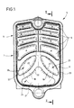
- the original feature of this boiler is located at the level of the intermediate elements reinforced 5 of which one is shown in detail on the figure 1.
- These reinforced intermediate elements are made up so that after assembly, the second part 16 of the combustion chamber 14 is fitted with exchange surfaces additional, formed by the presence of a group of additional water channels crossing the passage of flame and communicating with the envelope 17 of water circulation surrounding said combustion chamber.
- the chamber combustion 14 consists of the first classic part 15 in fully open space and the second part 16 partially closed transversely by the succession of water arms 18 and 19 of the reinforced exchangers 5 juxtaposed.
- the hot gases and smoke return to the front of the boiler along the flues A and are directed to the outlet of gases and fumes from combustion in the upper part of the rear panel 3 by the upper flues B arranged on several horizontal floors.
Landscapes
- Engineering & Computer Science (AREA)
- Physics & Mathematics (AREA)
- Thermal Sciences (AREA)
- Chemical & Material Sciences (AREA)
- Combustion & Propulsion (AREA)
- Mechanical Engineering (AREA)
- General Engineering & Computer Science (AREA)
- Instantaneous Water Boilers, Portable Hot-Water Supply Apparatuses, And Control Of Portable Hot-Water Supply Apparatuses (AREA)
- Details Of Fluid Heaters (AREA)
Description
- la figure 1 est une vue en élévation de l'élément échangeur intermédiaire renforcé équipant la chaudière selon l'invention ;
- la figure 2 est une vue schématique en coupe verticale selon la ligne II - II de la figure 1 d'une telle chaudière montrant l'emplacement des éléments échangeurs intermédiaires et la circulation des gaz et fumées de combustion.
- à puissance égale, elle permet de diminuer notablement le poids et le prix de revient final par un gain substantiel en matière, une réduction du temps de montage et un coût plus faible de transport ;
- la réduction de dimension des carneaux permet de diminuer la hauteur totale ;
- on peut augmenter la puissance totale de la chaudière tout en gardant son même encombrement en longueur ;
- la courbure inverse des bras d'eau permet de dégager des sections de passage suffisantes à un bon échange thermique dans le haut de la chambre de combustion et apporte une meilleure tenue aux dilatations et aux chocs thermiques.
Claims (10)
- Chaudière du type chaudière en fonte formée par une succession d'éléments échangeurs de chaleur, constituée d'un élément échangeur de façade avant (1) et d'un élément échangeur de façade arrière (3) et d'une pluralité d'éléments échangeurs intermédiaires (4) ou (5) présentant respectivement une section de passage de flamme, éléments échangeurs intermédiaires formant après assemblage-juxtaposition la chambre de combustion (14) ou foyer de la chaudière, les éléments échangeurs comportant une première série de carneaux pour le parcours dans le sens A de l'arrière vers l'avant de la chaudière et une deuxième série de carneaux pour le parcours dans le sens B de l'avant vers l'arrière de la chaudière des gaz chauds et fumées de combustion pour leur évacuation à l'arrière de la chaudière, et une enveloppe (17) de circulation d'eau entourant les sections de passage de flamme ou les gaz et fumées de combustion formant par succession horizontale la chambre de combustion (14) ou foyer, caractérisée en ce que le foyer est formé par la succession de deux zones dont une première zone (15) comportant des éléments échangeurs (4) à section libre (11) de passage de la flamme et une deuxième zone (16) succédant à la première formée sur une partie au moins de sa longueur d'éléments échangeurs (5) dont la section de passage (12) est traversée par une pluralité de bras d'eau formant dans le foyer des canaux aérauliques distincts (24), (25) et (26) apportant des surfaces supplémentaires d'échange le long desquelles est divisé et guidé le flux aéraulique produit par la flamme et en ce que le foyer se termine à l'arrière par l'élément échangeur de façade arrière (3) avec renvoi des gaz de combustion vers les carneaux.
- Chaudière selon la revendication précédente, caractérisée en ce que le volume intérieur de la chambre de combustion (14) ou foyer est occupé sur une partie de sa longueur arrière par une succession de deux bras d'eau (18) et (19).
- Chaudière selon l'une quelconque des revendications 1 ou 2, caractérisée en ce que la concavité des bras d'eau (18) et (19) est dirigée vers le haut.
- Chaudière selon l'une quelconque des revendications précédentes, caractérisée en ce que les bras d'eau (18) et (19) communiquent avec l'enveloppe (17) de circulation d'eau, d'une part en partie centrale supérieure de la chambre (14), et d'autre part par les parois latérales inférieures de ladite chambre.
- Elément intermédiaire pour la réalisation de la chaudière selon la revendication 1, caractérisé en ce que la cavité de chaque élément échangeur prévue pour la chambre de combustion (14) est traversée par des surfaces d'échange supplémentaires.
- Elément intermédiaire selon la revendication précédente, caractérisé en ce que les surfaces d'échange supplémentaires sont constituées par les parois des bras d'eau (18) et (19) traversant la chambre de combustion (14) en communication hydrauliques avec l'enveloppe d'eau (17) entourant la chambre de combustion (14).
- Elément intermédiaire selon la revendication précédente, caractérisé en ce que les bras d'eau (18) et (19) sont au nombre de deux.
- Elément intermédiaire selon l'une quelconque des revendications 5 à 7, caractérisé en ce que la concavité des bras d'eau (18) et (19) est dirigée vers le haut.
- Elément intermédiaire selon la revendication précédente, caractérisé en ce que les deux bras d'eau (18) et (19) sont symétriques et réunis entre eux à leur partie supérieure, et en ce qu'ils communiquent avec l'enveloppe d'eau (17) d'une part en partie centrale supérieure de la chambre (14), et d'autre part par les parties latérales inférieures de la chambre.
- Elément intermédiaire selon l'une quelconque des revendications 5 à 9, caractérisé en ce que les surfaces supplémentaires et les parois des bras d'eau (18) et (19) sont équipées de picots ou d'ailettes (20) favorisant l'échange de chaleur.
Applications Claiming Priority (2)
| Application Number | Priority Date | Filing Date | Title |
|---|---|---|---|
| FR9011591 | 1990-09-17 | ||
| FR9011591A FR2666873B1 (fr) | 1990-09-17 | 1990-09-17 | Chaudiere a elements intermediaires renforces. |
Publications (3)
| Publication Number | Publication Date |
|---|---|
| EP0477116A1 EP0477116A1 (fr) | 1992-03-25 |
| EP0477116B1 EP0477116B1 (fr) | 1995-01-04 |
| EP0477116B2 true EP0477116B2 (fr) | 1999-10-27 |
Family
ID=9400474
Family Applications (1)
| Application Number | Title | Priority Date | Filing Date |
|---|---|---|---|
| EP19910440074 Expired - Lifetime EP0477116B2 (fr) | 1990-09-17 | 1991-09-17 | Chaudière à éléments intermédiaires renforcés |
Country Status (3)
| Country | Link |
|---|---|
| EP (1) | EP0477116B2 (fr) |
| DE (1) | DE69106466T3 (fr) |
| FR (1) | FR2666873B1 (fr) |
Family Cites Families (2)
| Publication number | Priority date | Publication date | Assignee | Title |
|---|---|---|---|---|
| DE404369C (de) * | 1921-10-30 | 1924-10-17 | Gustave Nordon | Heizungskessel mit Wassermantel und im Feuerraum liegenden Wasserrohrreihen |
| DE8901203U1 (fr) * | 1988-02-06 | 1989-03-23 | Joh. Vaillant Gmbh U. Co, 5630 Remscheid, De |
-
1990
- 1990-09-17 FR FR9011591A patent/FR2666873B1/fr not_active Expired - Fee Related
-
1991
- 1991-09-17 EP EP19910440074 patent/EP0477116B2/fr not_active Expired - Lifetime
- 1991-09-17 DE DE1991606466 patent/DE69106466T3/de not_active Expired - Fee Related
Also Published As
| Publication number | Publication date |
|---|---|
| DE69106466T3 (de) | 2000-06-15 |
| DE69106466T2 (de) | 1995-06-22 |
| FR2666873B1 (fr) | 1995-07-21 |
| DE69106466D1 (de) | 1995-02-16 |
| EP0477116B1 (fr) | 1995-01-04 |
| FR2666873A1 (fr) | 1992-03-20 |
| EP0477116A1 (fr) | 1992-03-25 |
Similar Documents
| Publication | Publication Date | Title |
|---|---|---|
| FR2757259A1 (fr) | Ailette metallique perfectionnee pour echangeur de chaleur, notamment pour vehicule automobile | |
| CA1212280A (fr) | Chaudiere a condensation | |
| EP0477116B2 (fr) | Chaudière à éléments intermédiaires renforcés | |
| FR2929388A1 (fr) | Echangeur de chaleur a puissance frigorifique elevee | |
| EP2013541B1 (fr) | Foyer ferme de cheminee a combustion amelioree et a temperature de fonctionnement augmentee | |
| EP0373027A1 (fr) | Chaudière à condensation pour chauffage à fluide caloporteur | |
| FR2553869A1 (fr) | Chaudiere a condensation pour chauffage a fluide caloporteur | |
| EP0271392B1 (fr) | Chaudière à combustible solide et plus particulièrement, chaudière à bois | |
| FR2512190A3 (fr) | Element de chaudiere pourvu d'ailettes d'echange thermique a profil special | |
| EP0193433A1 (fr) | Installation de chauffage pour cheminée à foyer ouvert et tirage inversé | |
| FR2619205A1 (fr) | Echangeur de chaleur a impact de jet | |
| FR2770625A1 (fr) | Element echangeur de chaleur a haut rendement destine a constituer le corps de chauffe d'une chaudiere sectionnable | |
| EP0102911A2 (fr) | Dispositif pour la récupération de calories dans un foyer et procédé pour sa réalisation | |
| BE481561A (fr) | ||
| FR2542851A1 (fr) | Recuperateur de chaleur a double circuit | |
| FR2492060A1 (fr) | Recuperateur de chaleur a tubes triangulaires | |
| FR2601116A1 (fr) | Echangeur pour foyer insert de cheminee | |
| BE475880A (fr) | ||
| FR2692756A1 (fr) | Ensemble de production d'air chaud, notamment pour fours de boulangerie, pâtisserie, ou analogue, à chariots fixes ou mobiles à recyclage d'air. | |
| BE457813A (fr) | ||
| BE477253A (fr) | ||
| FR2516210A1 (fr) | Dispositif de recuperation de chaleur pour cheminee d'interieur | |
| FR2658590A2 (fr) | Dispositif de recuperation de chaleur pour cheminee a atre. | |
| FR2497926A1 (fr) | Chaudiere sectionnee a haut rendement pour la production d'eau chaude ou de vapeur basse pression | |
| EP0443931A1 (fr) | Dispositif de récupération de chaleur pour cheminées à âtre |
Legal Events
| Date | Code | Title | Description |
|---|---|---|---|
| PUAI | Public reference made under article 153(3) epc to a published international application that has entered the european phase |
Free format text: ORIGINAL CODE: 0009012 |
|
| AK | Designated contracting states |
Kind code of ref document: A1 Designated state(s): CH DE ES GB IT LI |
|
| 17P | Request for examination filed |
Effective date: 19920725 |
|
| 17Q | First examination report despatched |
Effective date: 19930715 |
|
| GRAA | (expected) grant |
Free format text: ORIGINAL CODE: 0009210 |
|
| AK | Designated contracting states |
Kind code of ref document: B1 Designated state(s): CH DE ES GB IT LI |
|
| PG25 | Lapsed in a contracting state [announced via postgrant information from national office to epo] |
Ref country code: GB Effective date: 19950104 Ref country code: ES Free format text: THE PATENT HAS BEEN ANNULLED BY A DECISION OF A NATIONAL AUTHORITY Effective date: 19950104 |
|
| REF | Corresponds to: |
Ref document number: 69106466 Country of ref document: DE Date of ref document: 19950216 |
|
| ITF | It: translation for a ep patent filed |
Owner name: MARIETTI E GISLON S.R.L. |
|
| GBV | Gb: ep patent (uk) treated as always having been void in accordance with gb section 77(7)/1977 [no translation filed] |
Effective date: 19950104 |
|
| PLBI | Opposition filed |
Free format text: ORIGINAL CODE: 0009260 |
|
| 26 | Opposition filed |
Opponent name: RAPIDO WAERMETECHNIK GMBH Effective date: 19950929 |
|
| PLBF | Reply of patent proprietor to notice(s) of opposition |
Free format text: ORIGINAL CODE: EPIDOS OBSO |
|
| PGFP | Annual fee paid to national office [announced via postgrant information from national office to epo] |
Ref country code: CH Payment date: 19960912 Year of fee payment: 6 |
|
| PG25 | Lapsed in a contracting state [announced via postgrant information from national office to epo] |
Ref country code: LI Free format text: LAPSE BECAUSE OF NON-PAYMENT OF DUE FEES Effective date: 19970930 Ref country code: CH Free format text: LAPSE BECAUSE OF NON-PAYMENT OF DUE FEES Effective date: 19970930 |
|
| REG | Reference to a national code |
Ref country code: CH Ref legal event code: PL |
|
| PLAW | Interlocutory decision in opposition |
Free format text: ORIGINAL CODE: EPIDOS IDOP |
|
| PLAW | Interlocutory decision in opposition |
Free format text: ORIGINAL CODE: EPIDOS IDOP |
|
| PUAH | Patent maintained in amended form |
Free format text: ORIGINAL CODE: 0009272 |
|
| STAA | Information on the status of an ep patent application or granted ep patent |
Free format text: STATUS: PATENT MAINTAINED AS AMENDED |
|
| 27A | Patent maintained in amended form |
Effective date: 19991027 |
|
| AK | Designated contracting states |
Kind code of ref document: B2 Designated state(s): CH DE ES GB IT LI |
|
| PG25 | Lapsed in a contracting state [announced via postgrant information from national office to epo] |
Ref country code: IT Free format text: LAPSE BECAUSE OF NON-PAYMENT OF DUE FEES;WARNING: LAPSES OF ITALIAN PATENTS WITH EFFECTIVE DATE BEFORE 2007 MAY HAVE OCCURRED AT ANY TIME BEFORE 2007. THE CORRECT EFFECTIVE DATE MAY BE DIFFERENT FROM THE ONE RECORDED. Effective date: 20050917 |
|
| PGFP | Annual fee paid to national office [announced via postgrant information from national office to epo] |
Ref country code: DE Payment date: 20060921 Year of fee payment: 16 |
|
| PG25 | Lapsed in a contracting state [announced via postgrant information from national office to epo] |
Ref country code: DE Free format text: LAPSE BECAUSE OF NON-PAYMENT OF DUE FEES Effective date: 20080401 |