EP0476964B1 - Verfahren und Vorrichtung zum Abtasten eines gekennzeichneten Dokuments - Google Patents
Verfahren und Vorrichtung zum Abtasten eines gekennzeichneten Dokuments Download PDFInfo
- Publication number
- EP0476964B1 EP0476964B1 EP91308456A EP91308456A EP0476964B1 EP 0476964 B1 EP0476964 B1 EP 0476964B1 EP 91308456 A EP91308456 A EP 91308456A EP 91308456 A EP91308456 A EP 91308456A EP 0476964 B1 EP0476964 B1 EP 0476964B1
- Authority
- EP
- European Patent Office
- Prior art keywords
- document
- scanning
- page
- signature
- platen
- Prior art date
- Legal status (The legal status is an assumption and is not a legal conclusion. Google has not performed a legal analysis and makes no representation as to the accuracy of the status listed.)
- Expired - Lifetime
Links
- 238000000034 method Methods 0.000 title claims description 19
- 238000003384 imaging method Methods 0.000 claims description 24
- 238000012360 testing method Methods 0.000 description 14
- 238000012545 processing Methods 0.000 description 11
- 108091008695 photoreceptors Proteins 0.000 description 4
- 230000004044 response Effects 0.000 description 4
- 230000000881 depressing effect Effects 0.000 description 3
- 238000010586 diagram Methods 0.000 description 3
- 238000012546 transfer Methods 0.000 description 3
- 239000011230 binding agent Substances 0.000 description 2
- 230000005540 biological transmission Effects 0.000 description 2
- 230000000977 initiatory effect Effects 0.000 description 2
- 239000000463 material Substances 0.000 description 2
- 230000003287 optical effect Effects 0.000 description 2
- 238000003491 array Methods 0.000 description 1
- 230000015572 biosynthetic process Effects 0.000 description 1
- 239000003086 colorant Substances 0.000 description 1
- 238000004891 communication Methods 0.000 description 1
- 230000006835 compression Effects 0.000 description 1
- 238000007906 compression Methods 0.000 description 1
- 238000010276 construction Methods 0.000 description 1
- 238000013481 data capture Methods 0.000 description 1
- 238000000354 decomposition reaction Methods 0.000 description 1
- 238000001514 detection method Methods 0.000 description 1
- 230000009977 dual effect Effects 0.000 description 1
- 230000000694 effects Effects 0.000 description 1
- 238000012840 feeding operation Methods 0.000 description 1
- 238000001914 filtration Methods 0.000 description 1
- 239000011521 glass Substances 0.000 description 1
- 230000002452 interceptive effect Effects 0.000 description 1
- 230000003134 recirculating effect Effects 0.000 description 1
- 238000012216 screening Methods 0.000 description 1
Images








Classifications
-
- H—ELECTRICITY
- H04—ELECTRIC COMMUNICATION TECHNIQUE
- H04N—PICTORIAL COMMUNICATION, e.g. TELEVISION
- H04N1/00—Scanning, transmission or reproduction of documents or the like, e.g. facsimile transmission; Details thereof
- H04N1/32—Circuits or arrangements for control or supervision between transmitter and receiver or between image input and image output device, e.g. between a still-image camera and its memory or between a still-image camera and a printer device
- H04N1/32358—Circuits or arrangements for control or supervision between transmitter and receiver or between image input and image output device, e.g. between a still-image camera and its memory or between a still-image camera and a printer device using picture signal storage, e.g. at transmitter
- H04N1/32459—Circuits or arrangements for control or supervision between transmitter and receiver or between image input and image output device, e.g. between a still-image camera and its memory or between a still-image camera and a printer device using picture signal storage, e.g. at transmitter for changing the arrangement of the stored data
- H04N1/32464—Changing the arrangement of pages or documents, e.g. for producing pages to be bound
-
- H—ELECTRICITY
- H04—ELECTRIC COMMUNICATION TECHNIQUE
- H04N—PICTORIAL COMMUNICATION, e.g. TELEVISION
- H04N1/00—Scanning, transmission or reproduction of documents or the like, e.g. facsimile transmission; Details thereof
- H04N1/04—Scanning arrangements, i.e. arrangements for the displacement of active reading or reproducing elements relative to the original or reproducing medium, or vice versa
-
- H—ELECTRICITY
- H04—ELECTRIC COMMUNICATION TECHNIQUE
- H04N—PICTORIAL COMMUNICATION, e.g. TELEVISION
- H04N1/00—Scanning, transmission or reproduction of documents or the like, e.g. facsimile transmission; Details thereof
- H04N1/38—Circuits or arrangements for blanking or otherwise eliminating unwanted parts of pictures
-
- H—ELECTRICITY
- H04—ELECTRIC COMMUNICATION TECHNIQUE
- H04N—PICTORIAL COMMUNICATION, e.g. TELEVISION
- H04N1/00—Scanning, transmission or reproduction of documents or the like, e.g. facsimile transmission; Details thereof
- H04N1/387—Composing, repositioning or otherwise geometrically modifying originals
-
- H—ELECTRICITY
- H04—ELECTRIC COMMUNICATION TECHNIQUE
- H04N—PICTORIAL COMMUNICATION, e.g. TELEVISION
- H04N1/00—Scanning, transmission or reproduction of documents or the like, e.g. facsimile transmission; Details thereof
- H04N1/387—Composing, repositioning or otherwise geometrically modifying originals
- H04N1/3872—Repositioning or masking
- H04N1/3873—Repositioning or masking defined only by a limited number of coordinate points or parameters, e.g. corners, centre; for trimming
-
- H—ELECTRICITY
- H04—ELECTRIC COMMUNICATION TECHNIQUE
- H04N—PICTORIAL COMMUNICATION, e.g. TELEVISION
- H04N2201/00—Indexing scheme relating to scanning, transmission or reproduction of documents or the like, and to details thereof
- H04N2201/32—Circuits or arrangements for control or supervision between transmitter and receiver or between image input and image output device, e.g. between a still-image camera and its memory or between a still-image camera and a printer device
- H04N2201/3285—Circuits or arrangements for control or supervision between transmitter and receiver or between image input and image output device, e.g. between a still-image camera and its memory or between a still-image camera and a printer device using picture signal storage, e.g. at transmitter
- H04N2201/3288—Storage of two or more complete document pages or image frames
Definitions
- the invention relates generally to an electronic reprographic system, and more especially to methods and apparatus for electronically scanning bound, or other signature-type, input documents.
- a signature-type document is a sheet typically containing four numbered pages which when folded and nested inside one another become one unit of a pamphlet or book.
- a signature-type document is a sheet typically containing four numbered pages which when folded and nested inside one another become one unit of a pamphlet or book.
- scanning the facing page requires the manual repositioning of the book or document to a fixed registration position prior to initiating the scanning operation.
- U S. Patent No 4,731,637 to Acquaviva et al. discloses a registration gate which is retractably insertable having first and second registration sides spaced apart by a preset defined distance. Documents are fed to an imaging station for "two-up" copying with a registered spacing between them determined by a gate thickness.
- U. S. Patent No. 4,334,765 to Clark also teaches an apparatus comprising an automatic document feeder in which copies may be reduced in size and placed contiguous one another on both sides of a copy sheet in a sequence facilitating booklet assembly.
- 4,783,682 to Maehara discloses a method which comprises correctly aligning a tip position of a copy paper by operating a timer and a counter.
- "one-set / two-copy" mode is entered for continuously copying, both a left half and a right half of a two sided original are copied onto individual copying papers.
- an apparatus capable of copying a bound document while eliminating the offset inherent in the copy of the second page is taught in U.S. Patent No. 4,739,372 to Watanabe.
- the image forming apparatus disclosed provides dual-page copies of a document that are free of offset.
- U.S. Patent No. 4,674,864 to Stackenborg et al. also teaches a device having control means for accepting data concerning the width of oppositely located image-free edge zones, whereby said control means ultimately determines the imaging ratio and a final width of the image-free edge zones. An operator need not reinput these data for each copying job.
- U.S. Patent No. 4,659,207 to Maekawa discloses a method comprising a switchable mode enabling the starting of an exposure from either one end or the center of a glass platen according to an operation signal. Copies are formed on both sides of a copy paper or on two different copy papers selectively.
- U.S. Patent No. 4,353,638 to Knechtel discloses an apparatus which produces copies during a forward scanning time and a backward scanning time. During backward scanning, a reflector is interposed in the optical path to further reflect and invert the image exposed on the photoconductive drum.
- an electronic imaging apparatus comprising, a platen on which documents to be scanned are located; a reciprocating scanning device for scanning an input document located on the platen; means for moving the scanning device to scan a first input document in a first direction and a second input document in the reverse direction; characterised by means for outputting image signals associated with scanning a document in said first direction, whereby the orientation of said image signals is in a first orientation; means for outputting image signals associated with scanning a document in said reverse direction, whereby the orientation of said image signals is in a reversed orientation; and an electronic signal for indicating the orientation of the image signals being output by said system.
- a method of scanning a pair of signature-type input documents, having an A page and a B page on the face thereof, in a single scanning cycle using apparatus having a platen and a reciprocating scanning device for scanning a signature-type input document located on the platen to generate image signals representative of the input documents comprising the steps of: locating the first signature-type input document on said platen; scanning the image region associated with said A page in a first direction to generate image signals of a first orientation; scanning the image region associated with said B page in said first direction to generate the image signals of a first orientation; outputting, as a result of the steps of scanning in a first direction, the image signals of the first orientation; reversing the direction of said reciprocating scanning device; locating said second signature-type input document on said platen; scanning the image region associated with said B page in said reverse direction to generate the image signals of a reverse orientation; scanning the image region associated with said A page in said reverse direction to generate the image signals of a reverse orientation; and
- the invention provides a printing system having a scanner section, a platen, a user interface suitable for the programming of dimensional information defining the desired imaging area of an input document page and a reciprocating scanning device for scanning the page or pages located on the platen, the method of scanning a first page pair, consisting of pages A and B of a bound document, and a second page pair, consisting of pages A' and B' of the document, in a single scan cycle, including the steps of:
- a high speed electronic imaging system having a scanner section, a platen, a user interface suitable for the programming of dimensional information defining the desired imaging area of an input document page and a reciprocating scanning device for scanning the page or pages located on the platen, comprising:
- the system may further comprise
- the signature-type document may comprise a plurality of pages bound together on a common edge, so as to resemble a book.
- the programming means of the system may then further comprise a video display;
- the signature-type document may be a single sheet signature unit.
- Said means for locating a signature-type document on the platen may then comprise:
- Printing system 2 for purposes of explanation is divided into a scanner section 6, controller section 7, and printer section 8. While a specific printing system is shown and described, the present invention may be used with other types of printing systems such as ink jet, ionographic, etc.
- scanner section 6 incorporates a transparent platen 20 on which the document 22 to be scanned is located.
- One or more linear arrays 24 are supported for reciprocating scanning movement below platen 20.
- Lens 26 and mirrors 28, 29, 30 cooperate to focus array 24 on a line like segment of platen 20 and the document being scanned thereon.
- Array 24 provides image signals or pixels representative of the image scanned which after suitable processing by processor 25, are output to controller section 7.
- Processor 25 converts the analog image signals output by array 24 to digital image signals and processes these signals as required to enable system 2 to store and handle the image data in the form required to carry out the job programmed. Processor 25 also provides enhancements and changes to the image signals such as filtering, thresholding, screening, cropping, reduction/enlarging, etc. Following any changes and adjustments in the job program, the document must be rescanned.
- Documents 22 to be scanned may be located on platen 20 for scanning by automatic document handler (ADF) 35 operable in either a Recirculating Document Handling (RDH) mode or a Semi-Automatic Document Handling (SADH) mode.
- a manual mode including a Book mode and a Computer Forms Feeder (CFF) mode are also provided, the latter to accommodate documents in the form of computer fanfold.
- document handler 35 has a document tray 37 in which documents 22 are arranged in stacks or batches. The documents 22 in tray 37 are advanced by vacuum feed belt 40 and document feed rolls 41 and document feed belt 42 onto platen 20 where the document is scanned by array 24. Following scanning, the document is removed from platen 20 by belt 42 and returned to tray 37 by document feed rolls 44.
- a document entry slot 46 provides access to the document feed belt 42 between tray 37 and platen 20 through which individual documents may be inserted manually for transport to platen 20. Feed rolls 49 behind slot 46 form a nip for engaging and feeding the document to feed belt 42 and onto platen 20. Following scanning, the document is removed from platen 20 and discharged into catch tray 48.
- computer forms material is fed through slot 46 and advanced by feed rolls 49 to document feed belt 42 which in turn advances a page of the fanfold material into position on platen 20.
- printer section 8 comprises a laser type printer and for purposes of explanation is separated into a Raster Output Scanner (ROS) section 87, Print Module Section 95, Paper Supply section 107, and Finisher 120.
- ROS 95 has a laser 91, the beam of which is split into two imaging beams 94.
- Each beam 94 is modulated in accordance with the content of an image signal input by acousto-optic modulator 92 to provide dual imaging beams 94.
- Beams 94 are scanned across a moving photoreceptor 98 of Print Module 95 by the mirrored facets of a rotating polygon 100 to expose two image lines on photoreceptor 98 with each scan and create the latent electrostatic images represented by the image signal input to modulator 92.
- Photoreceptor 98 is uniformly charged by corotrons 102 at a charging station preparatory to exposure by imaging beams 94.
- the latent electrostatic images are developed by developer 104 and transferred at transfer station 106 to a print media 108 delivered by Paper Supply section 107.
- Media 108 may comprise any of a variety of sheet sizes, types,and colors.
- the print media is brought forward in timed registration with the developed image on photoreceptor 98 from either a main paper tray 110 or from auxiliary paper trays 112, or 114.
- the developed image transferred to the print media 108 is permanently fixed or fused by fuser 116 and the resulting prints discharged to either output tray 118, or to finisher 120.
- Finisher 120 includes a stacker with stitcher 122 for stitching or stapling the prints together to form books and a thermal binder 124 for adhesively bindi ng the prints into books.
- controller section 7 is, for explanation purposes, divided into an image input controller 50, User Interface (U/I) 52, system controller 54, main memory 56, image manipulation section 58, and image output controller 60.
- U/I User Interface
- main memory 56 main memory 56
- image manipulation section 58 image output controller 60.
- the scanned image data input from processor 25 of scanner section 6 to controller section 7 is compressed by image compressor/ processor 51 of image input controller 50 on PWB 70-3.
- image compressor/processor 51 As the image data passes through compressor/processor 51, it is segmented into slices N scanlines wide, each slice having a slice pointer.
- the compressed image data together with slice pointers and any related image descriptors providing image specific information are placed in an image file.
- the image files, which represent different print jobs, are temporarily stored in system memory 61 which comprises a Random Access Memory or RAM pending transfer to main memory 56 where the data is held pending use.
- U/I 52 includes a combined operator controller/CRT display consisting of an interactive touchscreen 62, keyboard 64, and mouse 66.
- U/I 52 interfaces the operator with printing system 2, enabling the operator to program print jobs and other instructions, to obtain system operating information, instructions, programming information, diagnostic information, etc.
- the job data is placed in a job file 188 (shown in Figure 13). Items displayed on touchscreen 62 such as files and icons are actuated by either touching the displayed item on screen 62 with a finger or by using mouse 66 to point cursor 67 to the item selected and keying the mouse.
- Main memory 56 has plural hard disks 90-1, 90-2, 90-3 for storing machine Operating System software, machine operating data, and the scanned image data currently being processed.
- main memory 56 When the compressed image data in main memory 56 requires further processing, or is required for display on touchscreen 62 of U/I 52, or is required by printer section 8, the data is accessed in main memory 56. Where further processing other than that provided by processor 25 is required, the data is transferred to image manipulation section 58 on PWB 70-6 where the additional processing steps such as collation, make ready, decomposition, etc are carried out. Following processing, the data may be returned to main memory 56, sent to U/I 52 for display on touchscreen 62, or sent to image output controller 60.
- Image data output to image output controller 60 is decompressed and readied for printing by image generating processors 86 of PWBs 70-7, 70-8 (seen in Figure 5A). Following this, the data is output by dispatch processors 88, 89 on PWB 70-9 to printer section 8. Image data sent to printer section 8 for printing is normally purged from memory 56 to make room for new image data.
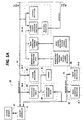
- control section 7 includes a plurality of Printed Wiring Boards (PWBs) 70, PWBs 70 being coupled with one another and with System Memory 61 by a pair of memory buses 72, 74.
- Memory controller 76 couples System Memory 61 with buses 72, 74.
- PWBs 70 include system processor PWB 70-1 having plural system processors 78; low speed I/O processor PWB 70-2 having U/I communication controller 80 for transmitting data to and from U/I 52; PWBs 70-3, 70-4, 70-5 having disk drive controller/processors 82 for transmitting data to and from disks 90-1, 90-2, 90-3 respectively of main memory 56 (image compressor/processor 51 for compressing the image data is on PWB 70-3); image manipulation PWB 70-6 with image manipulation processors of image manipulation section 58; image generation processor PWBs 70-7, 70-8 with image generation processors 86 for processing the image data for printing by printer section 8; dispatch processor PWB 70-9 having dispatch processors 88, 89 for controlling transmission of data to and from printer section 8; and boot control-arbitration-scheduler PWB 70-10.
- system processor PWB 70-1 having plural system processors 78
- low speed I/O processor PWB 70-2 having U/I communication controller 80 for transmitting data to and
- system control signals are distributed via a plurality of printed wiring boards (PWBs). These include EDN core PWB 130, Marking Imaging core PWB 132, Paper Handling core PWB 134, and Finisher Binder core PWB 136 together with various Input/Output (I/O) PWBs 138.
- a system bus 140 couples the core PWBs 130, 132, 134, 136 with each other and with controller section 7 while local buses 142 serve to couple the I/O PWBs 138 with each other and with their associated core PWB.
- the Operating System software is loaded from memory 56 to EDN core PWB 130 and from there to the remaining core PWBs 132, 134, 136 via bus 140, each core PWB 130, 132, 134, 136 having a boot ROM 147 for controlling downloading of Operating System software to the PWB, fault detection, etc.
- Boot ROMs 147 also enable transmission of Operating System software and control data to and from PWBs 130, 132, 134, 136 via bus 140 and control data to and from I/O PWBs 138 via local buses 142. Additional ROM, RAM, and NVM memory types are resident at various locations within system 2.
- jobs are programmed in a Job Program mode in which there is displayed on touchscreen 62 a Job Ticket 150 and a Job Scorecard 152 for the job being programmed.
- Job Ticket 150 displays the various job selections programmed while Job Scorecard 152 displays the basic instructions to the system for printing the job.
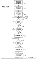
- FIGS 8A and 8B which display processing steps in accordance with the present invention as implemented in scanner section 6 and controller section 7 of Figure 2, the first step in initiating the signature document scanning mode is to program the document description, block 400.
- the document description programming touchscreen is accessed by first touching PAGE LEVEL tab 164 of Figure 7. This will subsequently disclose Job Scorecard 258 of Figure 9.
- touchscreen display 62 Upon selecting Document Description icon 262 of Figure 9, touchscreen display 62 will appear as shown in Figure 10.
- Document Description icon 260 is highlighted to indicate that Job Ticket area 262 represents the programmed features associated with the input document.
- bound document icon 264 In the case of a signature input document, the user would select bound document icon 264 to indicate that the input document contains a pair of pages which face one another.
- the icon would become highlighted and Job Ticket area 262 would be changed to reflect the programming options associated with the bound or signature-type input document selection as illustrated in Figure 11A.
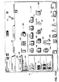
- Figures 11A and 11B which display the touchscreen associated with the bound input document programming selections, the user is able to specify the size of the input document on icon line 270, in accordance with the actual size of the input document.
- the user may select Other icon 272. Selection of icon 272 causes window 274 of Figure 11B to appear.
- Window 274 prompts the operator to enter, via keyboard 64 of Figure 1, the actual dimensions of the input document. More specifically, the user enters values associated with page width, display box 276, and page height, display box 278. After entering the correct values, the user completes the sequence by touching the Close button, 280.
- any of the touching or selection actions described herein may be accomplished via the known practices of; a) physically touching touchscreen 62, or b) moving cursor 67 to the desired location, by moving mouse 66 of Figure 1, and depressing one of the mouse buttons to indicate the selection.
- Icon line 282 contains icons which represent various combinations of sides of the input document which are to be scanned. For example, icons 284 or 286 would be selected to scan only side A or Side B of the input document. Icon 288 would be selected to scan both sides of the document.
- the user may select either icon 290 or 292 to program the system to separate the pages into two independent pages, icon 290, or to keep the two pages incorporated into one single image, icon 292.
- the user may specify the area at the center of the document that is not to be imaged, the gutter region, using make smaller button 294a or make larger button 294b. More specifically, the user scrolls to a value, displayed in window 296, that corresponds to the distance between the inside edge of the image area and the center of the bound region or fold line. For example, if the user scrolls to a gutter value of 0.5 inches, the system will remove a 1.0 inch section from the center of the scanned image, 0.5 inches from both sides. The distance is generally considered the gutter distance and is indicated in Figure 14 and 15 by reference numeral 344. Effectively, this value disables the storage of video image signals within the gutter region. In addition, the system controller subsequently utilizes the gutter value for the determination of the maximum image area width.
- Figure 12 displays Special Job Scorecard 300, which is accessed by selecting button 284 at the top of Job Scorecard 258 in Figure 11A. It is an option to further limit the area of the original document page that is to be scanned by selecting Crop icon 302, as shown at block 402 of Figure 8A.
- Crop icon 302 U/I 52 will immediately display the touchscreen illustrated in Figure 13. Referring now to Figure 13, Crop icon 302 is now highlighted indicative of the selection and the Job Scorecard area is used to illustrate the possible cropping selections available to the user. Specifically, when Edge Trim icon 304 is selected, the U/I displays document frame 306 which indicates the currently selected cropping coordinates as margins.
- the user may use adjustment button pairs 308, 310, 312 and 314 to adjust the top, bottom, left and right cropping margins, respectively. Adjustment of the image cropping area effectively alters the size of the document that will be scanned, thereby eliminating or cropping the area outside of the specified border.
- the cropping capability further defines the area of the input document that is to be scanned. For example, the user may utilize the cropping capability to remove non-printed margins that are present along the unbound edges of the input document pages.
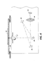
- Figures 14 and 15 respectively display schematic and plan views of imaging platen 20 of Figure 3, where document 330 has been placed upon the imaging platen.
- Document 330 illustrated as a bound document, has both an A imaging side and a B imaging side located on two opposing pages of the document. More appropriately, document 330 may be any signature-type document having distinct images formed on a single surface thereof, wherein the images may represent two opposing pages of a signature unit.
- Document 330 is shown registered in the center of imaging platen 20, along line X-X', in accordance with the present invention, thereby facilitating the registration of any bound document against side registration edge 332 only.
- the left margin distance becomes the Crop Offset Distance, 340, for the input document.
- the Crop Distance, 342 is determined by subtracting the sum of the left and right margin distances from the document page width as previously described. Also illustrated in Figure 15 are the top and bottom margins, 346 and 348 respectively. It should be noted that the cropping parameters have been illustrated and described in the slow scan direction as equivalent for both sides A and B of the input document, for reasons of simplicity of explanation only.
- system controller 54 of Figure 2 retrieves the document description and cropping parameters from system memory 56 and calculates the image cropping area (block 404), as previously described.
- the system controller Upon completion of the processing step at block 404, the system controller will have determined the active image scanning regions (D-E, F-G) for input document 330.
- the system controller awaits an indication that the document has been registered on the platen (test block 406).
- the affirmative response for the Start Scan test may come from one of two sources. First, in the open platen scanning mode, where a user may be scanning a bound original document, the affirmative response would be caused by the user depressing Start Scan button 162 of Figure 7. Second, in SADH mode, the the affirmative response may also be generated by the successful feeding and center registration of a single document sheet from document entry slot 46 of Figure 3, whereby the feeding operation is initiated by the the user depressing the Start Scan button. Subsequently, processor 25 of Figure 2 executes test block 408, to determine if side A of document 330 has been selected for imaging. If so, array 24 of Figure 3 is indexed to position D, the outer cropping limit, where capture of line like segments or rasters of the document image is begun (block 410), and the array continues capturing image rasters as it moves towards position E.
- array 24 of Figure 7 Upon reaching position E, array 24 of Figure 7 will have captured the image data from the cropping area programmed by the user and further image data capture will be disabled. If image capture for side A has been completed, or if side A has not been selected (test block 408), the scan array indexes to a location between positions E and F of Figure 14. Next, the system controller tests to determine if side B has been selected for imaging (test block 412). If so, the array moves to position F where it begins capturing raster information associated with side B and once again, image data is captured over the entire cropping region from position F through position G (block 414). Upon completing the image capture, the array is indexed to a location beyond position G.
- scanning processor 25 reverses the scanning direction of the array and sets a flag bit in an image status message sent to system controller 7, indicating that subsequent image rasters will be transmitted to image compressor/processor 51 in reverse order (block 416). Then, the system controller awaits an indication that the job has been completed (test block 418). As an example, the indication may come from the user selecting Stop Scan button 166 of Figure 7, which would cause the completion of the scanning job (block 434). Alternatively, the user may turn the page of the input document, re-register it and select Start Scan, or feed another sheet in SADH mode as previously described. Either of these two operations would provide an indication that the job has not been completed (test block 418), in addition to indicating that the user desires to start the scanning operation (test block 420).
- test block 420 a test is again run to determine if side B should be imaged (test block 422). If so, the array moves in a reverse, or left-to-right, direction back towards position G, where it again begins capturing image data, block 424, in the reversed orientation. Upon completing the image capture operation at point F, or if side B imaging is not selected, the array indexes to a location between positions F and E. Subsequently, test block 426 determines if side A is to be scanned, and if so, the image capture operation (block 428), is begun as the array moves past position E.
- the above system utilizing the apparatus and methods of the present invention as described herein, is capable of capturing signature-type original images at an increased rate by utilizing the full scanning range and bi-directional image capture capability of the scanning system.
- the scanning section utilizes a center registration mode for signature-type documents, thereby enabling rapid registration of the document on the imaging platen by either the user, in open platen mode, or by the document handler in SADH mode.
- the system presents the feature selections associated with the signature scanning mode in an organized, easily understandable iconic representation, enabling a user to rapidly program the features desired.
Landscapes
- Engineering & Computer Science (AREA)
- Multimedia (AREA)
- Signal Processing (AREA)
- Facsimiles In General (AREA)
- Control Or Security For Electrophotography (AREA)
- Facsimile Scanning Arrangements (AREA)
- Exposure Or Original Feeding In Electrophotography (AREA)
Claims (9)
- Elektronische Abbildungsvorrichtung, welche umfaßt eine Auflageplatte (20), auf die abzutastende Dokumente aufgelegt werden; eine hin- und hergehende Abtasteinrichtung (24) zum Abtasten von auf die Platte aufgelegten Dokumenten; Mittel zum Bewegen der Abtasteinrichtung zum Abtasten eines ersten Eingabe-Dokumentes in einer ersten Richtung und eines zweiten Eingabe-Dokumentes in der umgekehrten Richtung; gekennzeichnet durchMittel zum Ausgeben von dem Abtasten eines Dokuments zugehörigen Bildsignalen in der ersten Richtung, wodurch die Ausrichtung der Bildsignale in einer ersten Ausrichtung ist;Mittel zum Ausgeben von Bildsignalen, die dem Abtasten eines Dokumentes in der Umkehrrichtung zugeordnet sind, wodurch die Ausrichtung dieser Bildsignale sich in einer umgekehrten Ausrichtung befindet; undein elektronisches Signal zum Anzeigen der Ausrichtung der durch das System ausgegebenen Bildsignale.
- Vorrichtung nach Anspruch 1, bei der das erste Eingangsdokument ein druckbogenartiges Dokument mit einer A- und einer B-Seite an einer Einzelfläche desselben ist, und bei der die Abtasteinrichtung bewegt wird, nur den mit der A-Seite verbundenen Bildbereich in der ersten Richtung abzutasten; und darauffolgend nur den zur B-Seite gehörigen Bildbereich in der ersten Richtung abzutasten.
- Vorrichtung nach Anspruch 1 oder 2, bei der das zweite Eingabedokument ein druckbogenartiges Dokument mit einer A'- und einer B'-Seite an einer einzigen Fläche desselben ist, und bei der das Abtastgerät bewegt wird, um nur den zur B'-Seite gehörigen Bildbereich in der zweiten Richtung abzutasten und daraufhin nur den zu der A'-Seite gehörigen Bildbereich in der zweiten Richtung abzutasten.
- Elektronische Abbildungsvorrichtung nach Anspruch 1, welche umfaßt:Programmierungsmittel (52, 56) zum Programmieren eines Satzspiegelversatzes (340), einer Satzspiegelbreite (342) und einer Seitengröße (270) für das abzutastende druckbogenartige Dokument, um den gewünschten Abtastbereich jeder Seite (A, B) eines druckbogenartigen Dokumentes zu bestimmen, unddas Mittel zum Bewegen der Abtasteinrichtung bei auf die Platte aufgelegtem Dokument zum Abtasten jeder Seite des . Dokumentes über die jeweilige Druckspiegelbreite.
- Vorrichtung nach Anspruch 4, bei der das Mittel zum Bewegen der Abtasteinrichtung bei auf die Platte aufgelegtem druckbogenartigen Dokument betreibbar ist, die Abtastrichtung umzukehren und die Abtasteinrichtung in der umgekehrten Richtung zu bewegen, um jede Seite des zweiten Dokuments über den jeweiligen Druckspiegel abzutasten.
- Vorrichtung nach Anspruch 4 oder 5, bei der das druckbogenartige Dokument eine Vielzahl miteinander an einer gemeinsamen Kante verbundener Seiten umfaßt, so daß es einem Buch ähnelt, und das Programmiermittel weiter umfaßt:eine Videoanzeige;Mittel zum Festlegen eines Satzbogentyps eines Originaleingabe-Dokumentes;Mittel zum Festlegen, welche Seite des Originaldokumentes abzubilden sind;Mittel zum Festlegen des aus dem Originaldokument abzugrenzenden Satzspiegelbereiches; undMittel zum Bezeichnen der Größe des Mittelsteges zwischen den Seiten eines druckbogenartigen Dokuments.
- Vorrichtung nach Anspruch 4 oder 5, bei der das druckbogenartige Dokument eine Einzelbogen-Druckbogeneinheit ist und die Vorrichtung weiter Mittel enthält zum Auflegen eines druckbogenartigen Dokumentes auf die Platte, welche umfassen:Mittel zum Aufnehmen eines Einzeldokumentenbogens;Mittel zum Bestimmen des Ortes der Mitte des Dokumentenbogens;Mittel zum Transportieren des Bogens zu der Platte; undMittel zum Positionieren des Dokumentes in der Weise, daß die Dokumentenmitte mit der Mittenausrichtungsposition der Platte ausgerichtet ist.
- Verfahren des Abtastens eines Paares von druckbogenartigen Eingabedokumenten mit jeweils einer A-Seite und einer B-Seite an einer Fläche desselben in einem einzigen Abtastzyklus unter Benutzung einer Vorrichtung mit einer Auflageplatte und einer sich hin- und herbewegenden Abtasteinrichtung zum Abtasten eines auf die Platte aufgelegten druckbogenartigen Eingangsdokumentes, um für das Eingangsdokument repräsentative Bildsignale zu erzeugen, welches Verfahren die Schritte umfaßt:Auflegen des ersten druckbogenartigen Eingabedokumentes auf die Platte;Abtasten des zu der A-Seite gehörigen Bildbereiches in einer ersten Richtung zum Erzeugen von Bildsignalen in einer ersten Ausrichtung (410);Abtasten des zu der B-Seite gehörigen Bildbereiches in der ersten Richtung zum Erzeugen der Bildsignale einer ersten Ausrichtung (414);Ausgeben der Bildsignale der ersten Ausrichtung als Ergebnis der Abtastschritte in der ersten Richtung;Umkehren der Richtung der sich hin- und herbewegenden Abtasteinrichtung (416);Auflegen des zweiten druckbogenartigen Eingabedokumentes auf die Platte;Abtasten des zu der B-Seite gehörigen Bildbereiches in der umgekehrten Richtung zum Erzeugen der Bildsignale einer umgekehrten Ausrichtung (424);Abtasten des zu der A-Seite gehörigen Bildbereiches in der umgekehrten Richtung zum Erzeugen der Bildsignale einer umgekehrten Ausrichtung (428); undAusgeben der Bildsignale in einer umgekehrten Ausrichtung als Ergebnis der Abtastschritte in einer umgekehrten Richtung, und dadurch Abschließen des Einzelzyklus mit der sich hin- und herbewegenden Abtasteinrichtung.
- Verfahren nach Anspruch 8 unter Benutzung einer Vorrichtung mit einer zum Programmieren von Maßinformation geeigneten Nutzer-Schnittstelle, wodurch der gewünschte Abbildungsbereich einer Eingabedokumentenseite definiert wird, welches Verfahren die Schritte enthält:a) Programmieren der Kenngrößen des Eingabedokumentes zum Bestimmen des gewünschten Abtastbereiches eines abzubildenden druckbogenartigen Dokuments (A, B), wobei die Kenngrößen umfassen:i) den Druckspiegelversatz,ii) die Druckspiegelbreite, undiii) die Seitengröße;wobei jeder Abtastschritt des Verfahrens das Abtasten der jeweiligen Seite über die Satzspiegelbreite umfaßt.
Applications Claiming Priority (2)
| Application Number | Priority Date | Filing Date | Title |
|---|---|---|---|
| US07/583,922 US5212568A (en) | 1990-09-17 | 1990-09-17 | Method and apparatus for scanning a signature document |
| US583922 | 1990-09-17 |
Publications (3)
| Publication Number | Publication Date |
|---|---|
| EP0476964A2 EP0476964A2 (de) | 1992-03-25 |
| EP0476964A3 EP0476964A3 (en) | 1992-08-19 |
| EP0476964B1 true EP0476964B1 (de) | 1997-04-02 |
Family
ID=24335165
Family Applications (1)
| Application Number | Title | Priority Date | Filing Date |
|---|---|---|---|
| EP91308456A Expired - Lifetime EP0476964B1 (de) | 1990-09-17 | 1991-09-17 | Verfahren und Vorrichtung zum Abtasten eines gekennzeichneten Dokuments |
Country Status (5)
| Country | Link |
|---|---|
| US (1) | US5212568A (de) |
| EP (1) | EP0476964B1 (de) |
| JP (1) | JPH04313951A (de) |
| CA (1) | CA2048147C (de) |
| DE (1) | DE69125440T2 (de) |
Families Citing this family (22)
| Publication number | Priority date | Publication date | Assignee | Title |
|---|---|---|---|---|
| JP2844281B2 (ja) * | 1992-04-16 | 1999-01-06 | 富士写真フイルム株式会社 | 画像記録装置 |
| US5937112A (en) * | 1993-10-28 | 1999-08-10 | Agfa-Gevaert N.V. | Interactive color image digitizing system having restricted memory capability |
| US5555077A (en) * | 1994-12-01 | 1996-09-10 | Xerox Corporation | Printer having an active user interface feature |
| US5636006A (en) * | 1996-04-17 | 1997-06-03 | Xerox Corporation | Apparatus and method for scanning a bound document using a wedge shaped platen with a moving mirror |
| US5847846A (en) * | 1996-04-17 | 1998-12-08 | Xerox Corporation | Apparatus and method for scanning a bound color document using a wedge shaped platen |
| US5619302A (en) * | 1996-04-17 | 1997-04-08 | Xerox Corporation | Apparatus and method for scanning a bound document using a wedge shaped platen |
| US5760925A (en) * | 1996-05-30 | 1998-06-02 | Xerox Corporation | Platenless book scanning system with a general imaging geometry |
| US5764383A (en) * | 1996-05-30 | 1998-06-09 | Xerox Corporation | Platenless book scanner with line buffering to compensate for image skew |
| US5726775A (en) * | 1996-06-26 | 1998-03-10 | Xerox Corporation | Method and apparatus for determining a profile of an image displaced a distance from a platen |
| US5943679A (en) * | 1996-10-30 | 1999-08-24 | Xerox Corporation | Multi-page document viewer having a focus image and recursively nested images of varying resolutions less than the resolution of the focus image |
| US6456732B1 (en) * | 1998-09-11 | 2002-09-24 | Hewlett-Packard Company | Automatic rotation, cropping and scaling of images for printing |
| NL1013142C2 (nl) * | 1999-09-27 | 2001-03-29 | Ocu Technologies B V | Werkwijze en inrichting voor het afdrukken van een set opeenvolgende origineelpagina's op een aantal ontvangstvellen ter vorming van een boekje. |
| DE10049752A1 (de) * | 1999-10-11 | 2001-05-10 | Heidelberger Druckmasch Ag | Verfahren zur Erkennung der Lagegenauigkeit von Register und Falz-oder Schneidkanten an flachen Exemplaren |
| US6741270B1 (en) * | 2000-01-19 | 2004-05-25 | Xerox Corporation | Systems and methods scaling a captured image using predetermined scale information |
| US7350078B1 (en) * | 2001-04-26 | 2008-03-25 | Gary Odom | User selection of computer login |
| US7324711B2 (en) * | 2004-02-26 | 2008-01-29 | Xerox Corporation | Method for automated image indexing and retrieval |
| US8179573B2 (en) * | 2004-12-21 | 2012-05-15 | Hewlett-Packard Development Company, L.P. | Scanning two images of media |
| US20070139386A1 (en) * | 2005-12-16 | 2007-06-21 | Xerox Corporation | Touch screen user interface for digital reprographic device with pop-up menu display |
| US7843611B2 (en) * | 2007-07-18 | 2010-11-30 | Kuwait University | High speed flatbed scanner comprising digital image-capture module with two-dimensional optical image photo-sensor or digital camera |
| US8913087B1 (en) * | 2009-07-22 | 2014-12-16 | Amazon Technologies, Inc. | Digital image cropping |
| JP5830837B2 (ja) * | 2010-09-01 | 2015-12-09 | 株式会社リコー | 画像読取装置および画像形成装置 |
| JP2016082314A (ja) * | 2014-10-14 | 2016-05-16 | 船井電機株式会社 | スキャナおよびスキャン方法 |
Family Cites Families (19)
| Publication number | Priority date | Publication date | Assignee | Title |
|---|---|---|---|---|
| US3994580A (en) * | 1975-02-24 | 1976-11-30 | Xerox Corporation | Optical system for scanning during reciprocal motion |
| US4103991A (en) * | 1976-12-03 | 1978-08-01 | Xerox Corporation | Optical system for scanning during reciprocal motion providing 180°r |
| JPS5824783B2 (ja) * | 1978-11-20 | 1983-05-23 | 株式会社リコー | 複写機の走査方法 |
| US4334765A (en) * | 1980-06-09 | 1982-06-15 | International Business Machines Corporation | Booklet preparation utilizing an electrophotographic apparatus |
| DE3026758A1 (de) * | 1980-07-15 | 1982-04-15 | Canon K.K., Tokyo | Kopiergeraet |
| JPS6135456A (ja) * | 1984-07-28 | 1986-02-19 | Konishiroku Photo Ind Co Ltd | 両面原稿複写方法 |
| US4752809A (en) * | 1984-10-31 | 1988-06-21 | Minolta Camera Kabushiki Kaisha | Copying machine for selective reproduction of images |
| US4611908A (en) * | 1984-12-24 | 1986-09-16 | Eastman Kodak Company | Apparatus and method for forming reproductions with desired margin areas |
| NL8500197A (nl) * | 1985-01-25 | 1986-08-18 | Oce Nederland Bv | Reproductieinrichting waarin de breedte van de beeldvrije randzones op een kopie kan worden gevarieerd. |
| US4688930A (en) * | 1985-02-18 | 1987-08-25 | Canon Kabushiki Kaisha | Original reading apparatus |
| JPS61201261A (ja) * | 1985-03-04 | 1986-09-05 | Sharp Corp | 転写紙送りタイミング制御装置 |
| JPS623241A (ja) * | 1985-06-28 | 1987-01-09 | Toshiba Corp | 画像形成装置 |
| JPS6218529A (ja) * | 1985-07-17 | 1987-01-27 | Toshiba Corp | 画像形成装置 |
| JPS6294837A (ja) * | 1985-10-22 | 1987-05-01 | Minolta Camera Co Ltd | 露光量設定装置 |
| US4731637A (en) * | 1987-03-23 | 1988-03-15 | Xerox Corporation | Automatic "two-up" document registration and feeding for copiers |
| US4837636A (en) * | 1987-10-22 | 1989-06-06 | Xerox Corporation | Motion sensor for sensing the relative position and velocity of a recording member |
| JP2730556B2 (ja) * | 1988-11-29 | 1998-03-25 | 三田工業株式会社 | 画像形成装置 |
| US5119206A (en) * | 1990-09-28 | 1992-06-02 | Xerox Corporation | System for printing bound documents |
| US5057869A (en) * | 1990-11-30 | 1991-10-15 | Xerox Corporation | System for scanning signature pages |
-
1990
- 1990-09-17 US US07/583,922 patent/US5212568A/en not_active Expired - Lifetime
-
1991
- 1991-07-30 CA CA002048147A patent/CA2048147C/en not_active Expired - Lifetime
- 1991-09-12 JP JP3233477A patent/JPH04313951A/ja active Pending
- 1991-09-17 EP EP91308456A patent/EP0476964B1/de not_active Expired - Lifetime
- 1991-09-17 DE DE69125440T patent/DE69125440T2/de not_active Expired - Lifetime
Also Published As
| Publication number | Publication date |
|---|---|
| CA2048147A1 (en) | 1992-03-18 |
| US5212568A (en) | 1993-05-18 |
| DE69125440T2 (de) | 1997-08-28 |
| DE69125440D1 (de) | 1997-05-07 |
| JPH04313951A (ja) | 1992-11-05 |
| CA2048147C (en) | 1994-10-25 |
| EP0476964A2 (de) | 1992-03-25 |
| EP0476964A3 (en) | 1992-08-19 |
Similar Documents
| Publication | Publication Date | Title |
|---|---|---|
| US5212568A (en) | Method and apparatus for scanning a signature document | |
| US5191429A (en) | Electronic printing system for printing multiple images with determination of the maximum number of reduced size images to be optimally printed on a sheet of detected size without interference | |
| US5260805A (en) | Process for identifying programming conflicts in electronic printing systems | |
| US5119206A (en) | System for printing bound documents | |
| EP0478270B2 (de) | Elektronisches reprographisches System | |
| US5107299A (en) | Printer job recovery of complete or partially complete jobs in an electronic reprographic printing system | |
| EP0478352B1 (de) | Elektronisches reprographisches Drucksystem | |
| JPH0758942A (ja) | 電子複写印刷システム | |
| EP0479495B1 (de) | Automatisch einstellbare Bildverschiebung für vorgeschnittene tabellierte Blätter | |
| EP0461920B1 (de) | Drucksysteme | |
| US5243439A (en) | Image relocation in an electronic reprographic system | |
| EP0488814B1 (de) | System zur Abtastung von Druckseiten | |
| US5187587A (en) | Handling of copy sensitive jobs in an electronic reprographic printing system using unidirectional and bidirectional delivery of copies to plural bins | |
| JP3691858B2 (ja) | 画像プルーフ方法及び電子複写印刷システム | |
| US7679777B2 (en) | Job supplement for electronic printing machines | |
| EP0478351A2 (de) | Blattzahlerzeugung und -formatierung für elektronische Reprographie- oder Druckprodukte | |
| EP0478353B2 (de) | Reprografisches Drucksystem | |
| EP0478335A2 (de) | Elektronisches Drucksystem | |
| US5128772A (en) | Handling of copy sensitive jobs in an electronic reprogaphic printing system |
Legal Events
| Date | Code | Title | Description |
|---|---|---|---|
| PUAI | Public reference made under article 153(3) epc to a published international application that has entered the european phase |
Free format text: ORIGINAL CODE: 0009012 |
|
| AK | Designated contracting states |
Kind code of ref document: A2 Designated state(s): DE FR GB |
|
| PUAL | Search report despatched |
Free format text: ORIGINAL CODE: 0009013 |
|
| AK | Designated contracting states |
Kind code of ref document: A3 Designated state(s): DE FR GB |
|
| 17P | Request for examination filed |
Effective date: 19930203 |
|
| 17Q | First examination report despatched |
Effective date: 19940824 |
|
| GRAG | Despatch of communication of intention to grant |
Free format text: ORIGINAL CODE: EPIDOS AGRA |
|
| GRAH | Despatch of communication of intention to grant a patent |
Free format text: ORIGINAL CODE: EPIDOS IGRA |
|
| GRAH | Despatch of communication of intention to grant a patent |
Free format text: ORIGINAL CODE: EPIDOS IGRA |
|
| GRAA | (expected) grant |
Free format text: ORIGINAL CODE: 0009210 |
|
| AK | Designated contracting states |
Kind code of ref document: B1 Designated state(s): DE FR GB |
|
| REF | Corresponds to: |
Ref document number: 69125440 Country of ref document: DE Date of ref document: 19970507 |
|
| ET | Fr: translation filed | ||
| PLBE | No opposition filed within time limit |
Free format text: ORIGINAL CODE: 0009261 |
|
| STAA | Information on the status of an ep patent application or granted ep patent |
Free format text: STATUS: NO OPPOSITION FILED WITHIN TIME LIMIT |
|
| 26N | No opposition filed | ||
| REG | Reference to a national code |
Ref country code: GB Ref legal event code: IF02 |
|
| PGFP | Annual fee paid to national office [announced via postgrant information from national office to epo] |
Ref country code: FR Payment date: 20100921 Year of fee payment: 20 |
|
| PGFP | Annual fee paid to national office [announced via postgrant information from national office to epo] |
Ref country code: GB Payment date: 20100916 Year of fee payment: 20 |
|
| PGFP | Annual fee paid to national office [announced via postgrant information from national office to epo] |
Ref country code: DE Payment date: 20100915 Year of fee payment: 20 |
|
| REG | Reference to a national code |
Ref country code: DE Ref legal event code: R071 Ref document number: 69125440 Country of ref document: DE |
|
| REG | Reference to a national code |
Ref country code: DE Ref legal event code: R071 Ref document number: 69125440 Country of ref document: DE |
|
| REG | Reference to a national code |
Ref country code: GB Ref legal event code: PE20 Expiry date: 20110916 |
|
| PG25 | Lapsed in a contracting state [announced via postgrant information from national office to epo] |
Ref country code: GB Free format text: LAPSE BECAUSE OF EXPIRATION OF PROTECTION Effective date: 20110916 |
|
| PG25 | Lapsed in a contracting state [announced via postgrant information from national office to epo] |
Ref country code: DE Free format text: LAPSE BECAUSE OF EXPIRATION OF PROTECTION Effective date: 20110918 |