EP0476951B1 - 45-Grad-Block - Google Patents
45-Grad-Block Download PDFInfo
- Publication number
- EP0476951B1 EP0476951B1 EP91308431A EP91308431A EP0476951B1 EP 0476951 B1 EP0476951 B1 EP 0476951B1 EP 91308431 A EP91308431 A EP 91308431A EP 91308431 A EP91308431 A EP 91308431A EP 0476951 B1 EP0476951 B1 EP 0476951B1
- Authority
- EP
- European Patent Office
- Prior art keywords
- block
- translucent
- end wall
- wall
- side faces
- Prior art date
- Legal status (The legal status is an assumption and is not a legal conclusion. Google has not performed a legal analysis and makes no representation as to the accuracy of the status listed.)
- Expired - Lifetime
Links
- 239000011521 glass Substances 0.000 claims description 22
- 239000010410 layer Substances 0.000 description 7
- 239000000463 material Substances 0.000 description 7
- 238000000034 method Methods 0.000 description 6
- 230000005540 biological transmission Effects 0.000 description 3
- 238000010276 construction Methods 0.000 description 3
- 239000011324 bead Substances 0.000 description 2
- 238000004134 energy conservation Methods 0.000 description 2
- 239000004570 mortar (masonry) Substances 0.000 description 2
- 238000000465 moulding Methods 0.000 description 2
- 239000000853 adhesive Substances 0.000 description 1
- 238000004026 adhesive bonding Methods 0.000 description 1
- 230000001070 adhesive effect Effects 0.000 description 1
- 239000004568 cement Substances 0.000 description 1
- 230000005494 condensation Effects 0.000 description 1
- 238000009833 condensation Methods 0.000 description 1
- 238000006073 displacement reaction Methods 0.000 description 1
- 230000004927 fusion Effects 0.000 description 1
- 230000004313 glare Effects 0.000 description 1
- 238000009434 installation Methods 0.000 description 1
- 230000001788 irregular Effects 0.000 description 1
- 238000012423 maintenance Methods 0.000 description 1
- 238000003825 pressing Methods 0.000 description 1
- 239000002356 single layer Substances 0.000 description 1
- 239000002023 wood Substances 0.000 description 1
Images
Classifications
-
- E—FIXED CONSTRUCTIONS
- E04—BUILDING
- E04C—STRUCTURAL ELEMENTS; BUILDING MATERIALS
- E04C1/00—Building elements of block or other shape for the construction of parts of buildings
- E04C1/42—Building elements of block or other shape for the construction of parts of buildings of glass or other transparent material
Definitions
- This invention relates to a translucent block and, more particularly, to a translucent block having a 45° dihedral angle formed by the projected planes of the side faces of the translucent block which can be utilized with similar translucent blocks and blocks of other shapes to provide various column and wall structures.
- the invention also includes the method of forming such column and wall structures.
- glass block for exterior and interior applications.
- Using glass block for various wall structures offers various aesthetic and design features, as well as provides various functional characteristics and advantages over other materials which may be used for similar purposes.
- glass block structures promote energy conservation through their insulating capability to reduce heat gain or loss and provide thermal efficiencies for energy conservation.
- glass block structures can control light transmission and glare, as well as reduce surface condensation, and draft and noise transmission. Because of their construction, glass block structures offer security advantages as well as maintaining light transmission therethrough. Further, glass block structures have the added advantage of ease of maintenance and installation.
- U.S. Patent No. Des. 114,085 discloses a corner block configuration having arcuate walls and appears to be formed of two halves having different configurations, one of the halves also has raised linear portions as an exterior design. The angle formed by the side walls appears to be a wider angle than 45°.
- U.S. Patent No. 2,086,185 discloses an integrally blown hollow glass block of regular hexagonal form. This prior art patent also discloses a masonry structure or wall including the hexagonal glass block positioned with mortar in a configuration where the hexagonal sides would combine to form the exterior surface of the structure or wall.
- U.S. Patent No. 2,281,524 discloses glass building blocks molded in a single piece and using a socket in socket construction.
- the disclosed glass block is formed at a 90° angle and has an open bottom.
- U.S. Patent No. 4,537,001 discloses building elements with sides that have mathematical relations to each other. Among the elements is a block whose upper and lower surfaces have a generally pentagonal shape.
- U.S. Patent No. 4,636,413 discloses a glass block that has at least approximately the shape of a sector of a circular cylinder, the side faces forming the sector of the circular cylinder and having an axis defined by the side faces of the cylinder including an angle of 45° or 90°.
- the end wall opposite the 45° or 90° axis is an arcuate end wall and the block is blown in a single piece.
- U.S. Patent No. 4,651,486 discloses a translucent block having a generally irregular hexagonal configuration which can be utilized with similar translucent blocks and blocks of other shapes to provide various column and wall structures. The method of forming such column and wall structures is also disclosed.
- U.S. Patent No. 4,719,735 discloses a translucent end cap for use with a translucent glass block.
- the end cap has top and bottom surfaces parallel to each other.
- the side surfaces are perpendicular to and joined to the top and bottom surfaces.
- a raised rear surface portion extends from the side surface to form a protrusion so that the end cap may be secured to an abutting side surface of a translucent glass block.
- U.S. Patent No. 4,852,321 discloses a translucent end block which may be secured to an exposed top or side abutting surface of a translucent block to provide a wall structure in which the exposed top or side surface of the wall structure does not require wood or similar coverings to form useable top or side surfaces.
- a block comprising, a pair of parallel upper and lower surfaces each having a generally pentagonal shape, and a pair of generally rectangular opposing side faces which are nonparallel, the projected planes of said side faces intersecting at a 45° dihedral angle, said side faces having a first preselected height and a first preselected width and joined perpendicularly to said upper and said lower surfaces, a generally rectangular first opposing end wall having said first preselected height and a second preselected width and being perpendicular to and joined to said upper and said lower surfaces proximal to said 45° dihedral angle, a second opposing end wall having said first preselected height and a third preselected width and being perpendicularly joined to said upper and said lower surfaces distal from said 45° dihedral angle, said second opposing wall being formed of two generally rectangular wall sections the outer surfaces of which meet to form an obtuse angle therebetween characterised in that said block is translucent and is formed
- a translucent block wall structure may be formed incorporating the translucent block as defined in the preceding paragraph, either as a corner piece between adjoining straight wall portions made up of regular sized translucent blocks, or together with similar translucent blocks to form a columnar structure.
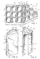
- the translucent block wall structure 10 includes a corner section 14 with conventional, straight translucent block wall sections integrally joined therewith.
- the corner section 14 is illustrated in greater detail in figures 4, 5, 7, 8, and 9.
- the translucent block wall structure 10 includes a plurality of translucent blocks 16 the extended planes of the side faces 22, 24 of which form a dihedral angle (a) at 45 degrees.
- One of the blocks 16 is illustrated in greater detail in figures 2 and 3.
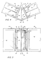
- Block 16 has a pair of parallel upper and lower surfaces 18 and 20 each having a generally pentagonal shape and generally rectangular side faces 22 and 24 which are nonparallel, the projected planes of side faces 22 and 24 intersecting at a 45° dihedral angle as shown as projected angle (a) in figure 4.
- This configuration provides the desired features which allow the block 16 to be used in numerous ways to provide walls and columns of translucent blocks.
- the preferred translucent block 16 has an upper surface 18 and a lower surface 20 of a generally pentagonal configuration which are identical.
- the upper surface 18 is shown in figures 2, 3, 4, 7, 8, and 9 and the lower surface 20 is indicated in figures 2, 3, 5 although not specifically visible therein.
- the block 16 also has two side faces 22 and 24 of a generally rectangular configuration of a first preselected height and a first preselected width and forming the side faces 22, 24 of the block 16.
- Side faces 22 and 24 are nonparallel with each other, the projected planes of the side faces 22 and 24 intersect at a 45 degree dihedral angle (a) as shown in figure 4, side faces 22, 24 are integrally joined to upper surface 18 and lower surface 20 of block 16 and side faces 22, 24 are perpendicular to the upper and lower surfaces 18, 20.
- the preferred block 16 also includes a first end wall 26, and a second end wall 28; the end walls 26 and 28 are of the same first preselected height as the side faces 22 and 24 and have a second and third preselected width.
- first end wall 26 is generally rectangular and is perpendicular to and joined to the upper surface 18 and the lower surface 20 and is joined to side faces 22, 24.
- the first end wall 26 is proximal to the 45 degree dihedral angle (a) formed by the projected planes of side faces 22 and 24.
- the first generally rectangular end wall 26 is bisected into two equal generally rectangular sections along its longitudinal axis, by the bead 38 formed in fusing the halves of the block 16 together.
- the second end wall 28 is in two equal sections 30 and 32 as can best be seen in figures 3 and 5.
- Each section 30 and 32 of second end wall 28 has the same first preselected height as side faces 22 and 24 and first end wall 26.
- Each section 30 and 32 of second end wall 28 forms an obtuse angle, the vertex of which is directed away from the first end wall 26.
- the equal sections 30, 32 of second end wall 28 are defined medially on the longitudinal axis of end wall 28 by the bead 38 formed in fusing the halves of block 16 together.
- the outer periphery of the side faces 22 and 24 and the upper and lower surfaces 18 and 20 preferably include a raised portion 36 to provide a slightly inward displacement of a substantial portion of the side faces 22, 24 and upper and lower surfaces 18, 20, to permit the joining of any side face 22, 24, or upper surface 18 or lower surface 20 of block 16 with other identical or different blocks in a translucent block structure.
- Block 16 can be formed from any suitable translucent material such as glass, and can be formed by any conventional glass block molding process known in the art.
- Block 16 is desirably a hollow glass block and is preferably formed by pressing two halves of block together at appropriate temperature and pressure conditions using known conventional processes and apparatus.
- Various design configurations can be formed on the surfaces of the glass block 16.
- second end wall 28 provides an exterior decorative appearance for the block 16, as generally indicated in figures 3 and 5, which significantly contributes to its overall aesthetic value.
- each of the halves of block 16 are identical and include one of the side faces 22, 24 and one half of first end wall 26, and one half of second end wall 28 which is either section 30 or 32 and one half of upper surface 18 and one half of lower surface 20.
- the preferred block 16 also includes a channel-like spacing 34 located medially along the longitudinal axes of first end wall 26 and second end wall 28.
- the preferred block 16 consists of the same function and purpose generally provided by the rounded and right angled corner blocks discussed in the prior art hereinabove. However, since the two halves of block 16 are identical, only one mold must be provided to basically form the identical half while at least two different molds should be required for the two different halves of the prior art corner blocks.
- the translucent block wall structure 10 also includes a plurality of translucent blocks 40 of a generally rectangular configuration.
- Blocks 40 can be selected from any number of conventional, generally rectangular translucent block configurations.
- the blocks 40 have a front face 42 and a rear face 44 which are generally rectangular.
- the front face 42 is shown in figures 1 and 6 and the rear face 44 is indicated in figures 1 and 6.
- the faces 42, 44 are substantially identical in appearance.
- the blocks 40 also have four abutting surfaces 46, 48, 50 and 52 which are generally rectangular as indicated in figures 1 and 6. Because the particular rectangular faces 42, 44 of the block 40 shown in the figures preferably form a square, the abutting surfaces 46, 48, 50, 52 are substantially similar to each other in appearance and configuration. However, because of the method of forming the block 40, in a normal use of any abutting surface to join any other abutting surface, the appearance of the abutting surface is not particularly governed by aesthetic consideration as might the appearance of the faces 42, 44.
- the blocks 40 would preferably be formed in a similar manner as the blocks 16 and the molding of separate halves thereof would again normally include a decorative design on the interior surfaces of the faces 42, 44 but not on those associated with the abutting surfaces 46, 48, 50, 52.
- the abutting surfaces 46, 48, 50, 52 of blocks 40 are fixedly joined to adjacent abutting surfaces of adjacent block 40 as indicated in figures 1 and 6.
- the abutting surfaces can be joined by a suitable bonding material 54, such as a conventional cementitious material or a suitable adhesive material.
- FIG. 1 there is illustrated a corner section 14 of translucent block in a layer 12 of the translucent block wall structure 10.
- a block 16 is joined by a suitable bonding material 54 such as mortar, at side faces 22 and 24 to abutting surfaces 46 of adjacent blocks 40.
- a suitable bonding material 54 such as mortar
- the heights and widths of the side faces 22, 24 and the abutting surfaces 46, 48, 50 and 52 should be substantially the same, or the sum of a combination of the heights and widths of side faces 22, 24 and abutting surfaces 46, 48, 50, 52 should be substantially the same.
- FIG 4 illustrates the cement or adhesive bonding 54 of the side faces 22, 24 of block 16 to abutting surfaces 46 of two blocks 40 to form a transparent block wall 10 with a 45° curve
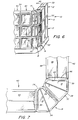
- corner section 14 of translucent block 16 can be formed by joining two blocks 16 to form a 90° curve in a transparent block wall 10 as illustrated in figure 7.
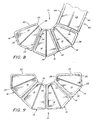
- three blocks 16 may be joined in the corner section 14 to make a transparent block wall structure 10 having a 135° curve.
- four blocks 16 may be joined as a corner section 14 to make a transparent block wall structure 10 having a 180° curve. Consequently the block 16 may be utilised to form a transparent block wall structure 10 having a desired curve of 45°, 90°, 135°, 180°, or combinations thereof.
- one of the primary features of the present invention includes a configuration having nonparallel side faces the projected planes of which form a dihedral 45° angle capable of being used as a corner section 14 in a transparent block wall structure 10 to make a curve of 45° or any other combination of 45° to provide flexibility in the construction of transparent block wall structures 10.
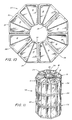
- a layer of translucent block 56 in a column structure 58 is illustrated from the top in schematic form.
- the translucent block column structure of the present invention may include any number of layers 56 as may be required to form a column 58, illustrated in figure 11.
- the upper surfaces 18 may be joined to the lower surfaces 20 of corresponding blocks 16 with a similar bonding material 54 in order to add sufficient integrity to the column structure 58.
- the present invention provides a generally rectangular translucent block, such as a glass block, the nonparallel side faces of which have projected planes forming a dihedral 45° angle, and translucent block wall structures and methods utilising a generally pentagonal translucent block with nonparallel side faces, the projected planes of the side faces forming a dihedral 45° angle, to enhance the uses of translucent block and translucent block structures.
- the present invention provides additional functional abilities and versatility for translucent block.
Landscapes
- Engineering & Computer Science (AREA)
- Architecture (AREA)
- Civil Engineering (AREA)
- Structural Engineering (AREA)
- Finishing Walls (AREA)
- Joining Of Building Structures In Genera (AREA)
- Toys (AREA)
- Fencing (AREA)
Claims (5)
- Block mit einem Paar von oberen und unteren Seiten (18, 20), die jeweils eine im wesentlichen pentagonale Form aufweisen, und mit einem Paar von im wesentlichen rechteckförmigen, einander gegenüberliegenden Seitenflächen (22, 24), die nicht parallel sind, wobei die Projektionsebenen der Seitenflächen (22, 24) sich in einem V-förmigen Winkel von 45° schneiden, wobei die erwähnten Seitenflächen (22, 24) eine erste vorgewählte Höhe und eine erste vorgewählte Breite aufweisen und an die oberen und unteren Seiten (18, 20) rechtwinklig anschließen, mit einer im wesentlichen rechteckförmigen ersten gegenüberliegenden Stirnwand (26), die die erste vorgewählte Höhe und eine zweite vorgewählte Breite aufweist und rechtwinklig zu und anschließend an die erwähnten oberen und unteren Seiten vorgesehen sind, und zwar proximal oder in der Nähe des V-Winkels mit 45°, mit einer zweiten, gegenüberliegenden Stirnwand (28), die die erste vorgewählte Höhe und eine dritte vorgewählte Breite aufweist und rechtwinklig an die oberen und unteren Flächen (18, 20) anschließt, und zwar distal bzw. entfernt von dem erwähnten 45°-V-Winkel, wobei die erwähnte zweite gegenüberliegende Wand (28) von zwei im wesentlichen rechteckförmigen Wandabschnitten (30, 32) gebildet ist, deren Außenflächen sich treffen, um zwischen sich einen stumpfen Winkel zu bilden,
dadurch gekennzeichnet, daß der erwähnte Block lichtdurchlässig oder durchscheinend ausgebildet und aus zwei identischen Hälften hergestellt ist, wobei jede Hälfte eine der beiden erwähnten Seitenflächen (22, 24), eine der anschließenden Hälften der ersten Stirnwand (26), eine der anschließenden Hälften der zweiten Stirnwand (28), von denen die Hälften der zweiten Stirnwand (28) jeweils von den erwähnten entsprechenden Wandabschnitten (30, 32) gebildet sind, sowie eine anschließende Hälfte der oberen und unteren Flächen (18, 20) aufweist. - Ein lichtdurchlässiger Block nach Anspruch 1, dadurch gekennzeichnet, daß die erste gegenüberliegende Stirnwand (26) und die zweite gegenüberliegende Stirnwand (28) jeweils eine kanalartige Ausnehmung (34) aufweisen, die medial zu den Längsachsen der erwähnten ersten gegenüberliegenden Stirnwand (26) und der erwähnten zweiten gegenüberliegenden Stirnwand (28) verläuft.
- Eine lichtdurchlässige Block-Wandstruktur mit einem ersten lichtdurchlässigen Block (16) nach Anspruch 1 oder 2, sowie mit wenigstens einem zweiten lichtdurchlässigen Block (16/40) an beiden Seiten hiervon, wobei jeder erwähnte zweite lichtdurchlässige Block (16/40) ein Paar von parallelen Ober- und Unterseiten (18, 20/48, 52) mit identischer Form sowie im wesentlichen rechteckförmige Seitenflächen (22, 24/46, 50) aufweist, die rechtwinklig an die oberen und unteren Seiten (18, 20/48, 52) anschließen, wobei die Seitenflächen (22, 24) des ersten Blocks (16) jeweils an eine rechteckförmige Fläche (22, 24/46, 50) eines erwähnten zweiten Blocks (16/40) anschließt, um eine horizontale Lage von ersten und zweiten Glasblöcken (16/40) in der Anordnung zu bilden.
- Eine lichtdurchlässige Block-Wandstruktur nach Anspruch 3, weiterhin mit einer Vielzahl von ersten Blöcken (16) und zweiten Blöcken (16/40), die in einer Vielzahl von horizontalen Lagen angeordnet sind, wobei die erwähnte obere Fläche (18) jedes erwähnten ersten Blocks (16) an die erwähnte untere Fläche (20) eines benachbarten, darüber angeordneten ersten Blockes (16) anschließt, und wobei die erwähnte obere Fläche (18, 48) jedes der erwähnten zweiten Blöcke (16/40) an die untere Fläche (20/52) jedes darüber angeordneten benachbarten Blocks (16/40) anschließt.
- Eine lichtdurchläsige Block-Wandstruktur nach Anspruch 4, dadurch gekennzeichnet, daß jeder zweite Glasblock identisch mit dem erwähnten ersten Glasblock (16) ist, so daß jede Lage eine kreisförmige Anordnung aus lichtdurchlässigen Glasblöcken (16) bildet und die Struktur eine säulenartige Struktur (56) ist, wobei die ersten gegenüberliegenden Stirnwände (26) die Innenfläche der säulenartigen Struktur (56) und die erwähnten zweiten gegenüberliegenden Stirnwände (28) die Außenfläche der erwähnten säulenartigen Struktur (56) bilden.
Applications Claiming Priority (2)
| Application Number | Priority Date | Filing Date | Title |
|---|---|---|---|
| US07/584,534 US5067295A (en) | 1990-09-18 | 1990-09-18 | 45 degree block |
| US584534 | 1996-01-11 |
Publications (2)
| Publication Number | Publication Date |
|---|---|
| EP0476951A1 EP0476951A1 (de) | 1992-03-25 |
| EP0476951B1 true EP0476951B1 (de) | 1994-12-07 |
Family
ID=24337712
Family Applications (1)
| Application Number | Title | Priority Date | Filing Date |
|---|---|---|---|
| EP91308431A Expired - Lifetime EP0476951B1 (de) | 1990-09-18 | 1991-09-16 | 45-Grad-Block |
Country Status (9)
| Country | Link |
|---|---|
| US (1) | US5067295A (de) |
| EP (1) | EP0476951B1 (de) |
| JP (1) | JPH04272353A (de) |
| AU (1) | AU642296B2 (de) |
| CA (1) | CA2049135C (de) |
| DE (1) | DE69105680T2 (de) |
| ES (1) | ES2067161T3 (de) |
| MX (1) | MX173974B (de) |
| TR (1) | TR25469A (de) |
Families Citing this family (15)
| Publication number | Priority date | Publication date | Assignee | Title |
|---|---|---|---|---|
| US5410848A (en) * | 1991-11-21 | 1995-05-02 | The Burns & Russell Company | Composite for turning a corner or forming a column, mold and method for producing glazed unit for such |
| US5212925A (en) * | 1991-11-21 | 1993-05-25 | Mcclinton John | Wall corner composite, mold and method for producing glazed unit for such |
| FR2687708B1 (fr) * | 1992-02-21 | 1998-11-20 | Frederic Ginailhac | Elements modulaires en bois servant aux montages de briques de verres. |
| US5384997A (en) * | 1992-05-18 | 1995-01-31 | The Burns & Russell Company | Column and corner composite, mold and method for producing glazed unit for such |
| DE4218215A1 (de) * | 1992-06-03 | 1993-12-09 | Ver Glaswerke Gmbh | Glasbaustein mit diffuser Lichtstreuung |
| CA2169436A1 (en) * | 1993-08-13 | 1995-02-23 | Randolf Andrew Wirkus | A glass brick wall |
| ES2134414T3 (es) * | 1994-11-11 | 1999-10-01 | Stonemarket Concrete Ltd | Recubrimiento de superficies. |
| US5675948A (en) * | 1995-04-13 | 1997-10-14 | Thermo-Vent Manufacturing, Inc. | Insulated ventilator for glass block window |
| US5813186A (en) * | 1997-02-24 | 1998-09-29 | Acksel; Ione | Construction blocks with complementary interstitial modules |
| USD577129S1 (en) * | 2007-01-12 | 2008-09-16 | Seves S.P.A. | Block for construction |
| USD580073S1 (en) * | 2007-05-30 | 2008-11-04 | Seves S.P.A. | Block for construction |
| US20090113815A1 (en) * | 2007-10-26 | 2009-05-07 | Terah Earl Woodcock | Tapered Hexagon Building Block |
| USD708352S1 (en) * | 2011-12-13 | 2014-07-01 | Saint-Gobain Glass France | Patterned glass |
| CN106267848A (zh) * | 2015-06-01 | 2017-01-04 | 林美足 | 鸠形积木 |
| US11072971B1 (en) * | 2020-01-24 | 2021-07-27 | Solar Innovations, Inc. | Modular system for glazing and other infill panels |
Citations (1)
| Publication number | Priority date | Publication date | Assignee | Title |
|---|---|---|---|---|
| US4537001A (en) * | 1983-05-23 | 1985-08-27 | Uppstroem Leif R | Building elements |
Family Cites Families (35)
| Publication number | Priority date | Publication date | Assignee | Title |
|---|---|---|---|---|
| US250635A (en) * | 1881-12-06 | Manufacture of glass building-blocks for sea-walls | ||
| BE567594A (de) * | ||||
| US298418A (en) * | 1884-05-13 | Feancis h | ||
| US402073A (en) * | 1889-04-23 | talconniee | ||
| US758973A (en) * | 1903-07-09 | 1904-05-03 | Edward Kaye | Glass-faced brick, tile, &c. |
| US827464A (en) * | 1905-09-02 | 1906-07-31 | Frank Pedrick | Ornamental brick. |
| US1425102A (en) * | 1918-03-11 | 1922-08-08 | Frederick L Keppler | Wall structure |
| US1855987A (en) * | 1931-02-16 | 1932-04-26 | Edward F Rammer | Brick |
| US1994387A (en) * | 1933-06-26 | 1935-03-12 | Cie Reunies Glaces Et Verres | Hollow transparent unit for construction |
| GB470835A (en) * | 1934-11-17 | 1937-08-23 | Genevieve Louise Dupuis | Improvements in athermanous elements of construction, and applications thereof |
| US2110900A (en) * | 1936-05-26 | 1938-03-15 | Owens Illinois Glass Co | Building block |
| US2115513A (en) * | 1936-06-23 | 1938-04-26 | Owens Illinois Glass Co | Wall construction |
| US2086185A (en) * | 1936-08-24 | 1937-07-06 | Sam B Meyer | Building block |
| US2110885A (en) * | 1936-10-31 | 1938-03-15 | Pittsburgh Plate Glass Co | Glass brick wall |
| US2115264A (en) * | 1937-02-13 | 1938-04-26 | William P Witherow | Load bearing glazed building block |
| FR848079A (fr) * | 1937-12-27 | 1939-10-23 | Saint Gobain | élément creux en verre pour la construction |
| US2226220A (en) * | 1938-12-10 | 1940-12-24 | Pittsburgh Plate Glass Co | Hollow structural block |
| US2322591A (en) * | 1940-04-19 | 1943-06-22 | Pittsburgh Corning Corp | Nonglare glass building block |
| US2306320A (en) * | 1940-10-10 | 1942-12-22 | Pittsburgh Corning Corp | Glass block assembly |
| US2281524A (en) * | 1940-11-25 | 1942-04-28 | Meyers Company | Glass building block |
| US2333723A (en) * | 1941-01-23 | 1943-11-09 | Pittsburgh Corning Corp | Composite building unit |
| US2355262A (en) * | 1941-06-10 | 1944-08-08 | Corning Glass Works | Construction block and method of manufacture |
| US2724260A (en) * | 1952-12-06 | 1955-11-22 | Pittsburgh Corning Corp | Glass block with mortar repellent coating |
| US2975853A (en) * | 1957-11-07 | 1961-03-21 | Albert W Friend | Sound absorbent translucent building block |
| BR6573585D0 (pt) * | 1965-09-29 | 1973-03-08 | Magnesita Sa | Novo e original sistema de fecho em material refratario moldado para arcos aneis e similares |
| US3714816A (en) * | 1969-06-12 | 1973-02-06 | North American Rockwell | Tubular transducer and dry couplant therefor |
| US3798861A (en) * | 1973-04-10 | 1974-03-26 | A Weiss | Wall construction module and system |
| US4023319A (en) * | 1975-06-09 | 1977-05-17 | Takao Kurata | Curtain wall assembly of interfitting glass blocks |
| DE3370170D1 (en) * | 1982-12-18 | 1987-04-16 | Rinninger Hans & Sohn | Paving block |
| FR2542353B1 (fr) * | 1983-03-09 | 1985-10-25 | Manon Gerard | Element de verre en particulier brique ou pave de verre |
| USD293477S (en) | 1984-02-24 | 1987-12-29 | Pittsburgh Corning Corporation | Translucent building block or the like |
| DE8437071U1 (de) * | 1984-12-18 | 1985-06-13 | Westerwald AG für Silikatindustrie, 5432 Wirges | Ecken-Glasstein |
| US4651486A (en) * | 1985-05-31 | 1987-03-24 | Pittsburgh Corning Corporation | Translucent block for wall and column structures |
| US4753622A (en) * | 1987-10-05 | 1988-06-28 | Yoshitsugu Nakama | Building block kit |
| US4852321A (en) * | 1987-12-07 | 1989-08-01 | Pittsburgh Corning Corporation | Translucent end block |
-
1990
- 1990-09-18 US US07/584,534 patent/US5067295A/en not_active Expired - Lifetime
-
1991
- 1991-07-31 TR TR91/0754A patent/TR25469A/xx unknown
- 1991-08-13 CA CA002049135A patent/CA2049135C/en not_active Expired - Lifetime
- 1991-09-06 JP JP3255810A patent/JPH04272353A/ja active Pending
- 1991-09-13 AU AU83885/91A patent/AU642296B2/en not_active Ceased
- 1991-09-16 EP EP91308431A patent/EP0476951B1/de not_active Expired - Lifetime
- 1991-09-16 ES ES91308431T patent/ES2067161T3/es not_active Expired - Lifetime
- 1991-09-16 DE DE69105680T patent/DE69105680T2/de not_active Expired - Fee Related
- 1991-09-17 MX MX9101121A patent/MX173974B/es unknown
Patent Citations (1)
| Publication number | Priority date | Publication date | Assignee | Title |
|---|---|---|---|---|
| US4537001A (en) * | 1983-05-23 | 1985-08-27 | Uppstroem Leif R | Building elements |
Also Published As
| Publication number | Publication date |
|---|---|
| JPH04272353A (ja) | 1992-09-29 |
| MX173974B (es) | 1994-04-12 |
| TR25469A (tr) | 1993-05-01 |
| DE69105680T2 (de) | 1995-05-24 |
| US5067295A (en) | 1991-11-26 |
| ES2067161T3 (es) | 1995-03-16 |
| AU642296B2 (en) | 1993-10-14 |
| AU8388591A (en) | 1992-03-26 |
| EP0476951A1 (de) | 1992-03-25 |
| CA2049135A1 (en) | 1992-03-19 |
| CA2049135C (en) | 1998-01-06 |
| DE69105680D1 (de) | 1995-01-19 |
Similar Documents
| Publication | Publication Date | Title |
|---|---|---|
| EP0476951B1 (de) | 45-Grad-Block | |
| EP0320077B1 (de) | Lichtdurchlässiger Abschlussstein | |
| US5230195A (en) | Insulating molded plastic building unit | |
| US4719735A (en) | Translucent end cap | |
| US2076472A (en) | Building construction | |
| US4891925A (en) | Interconnected construction blocks | |
| US4651486A (en) | Translucent block for wall and column structures | |
| US5732518A (en) | Arcuate building block structure | |
| US3798861A (en) | Wall construction module and system | |
| US4333287A (en) | System of lattice tiles | |
| US4944124A (en) | Decorative panel with cutline | |
| US5813186A (en) | Construction blocks with complementary interstitial modules | |
| JPH0129944B2 (de) | ||
| US4813904A (en) | Base element for the production of panels for a toy construction system | |
| EP0615567A1 (de) | Verbundelement zum Ausbilden von Ecken oder Säulen, Form und Verfahren zur Herstellung eines glasierten Elements. | |
| US3925950A (en) | Building block assembly | |
| US3503839A (en) | Decorative sheets made of plastics | |
| JP2892919B2 (ja) | 外装板 | |
| GB2182961A (en) | Triangular tile | |
| JPH0433933B2 (de) | ||
| KR200376713Y1 (ko) | 복층유리용 문살대의 3중 결합구조 | |
| JPH08158506A (ja) | セラミックブロックとその製造方法およびセラミックブロック壁 | |
| JPS636335Y2 (de) | ||
| JPH0122026Y2 (de) | ||
| KR100418629B1 (ko) | 건축용 판넬 |
Legal Events
| Date | Code | Title | Description |
|---|---|---|---|
| PUAI | Public reference made under article 153(3) epc to a published international application that has entered the european phase |
Free format text: ORIGINAL CODE: 0009012 |
|
| AK | Designated contracting states |
Kind code of ref document: A1 Designated state(s): AT BE CH DE DK ES FR GB GR IT LI LU NL SE |
|
| RBV | Designated contracting states (corrected) |
Designated state(s): BE CH DE ES FR GB IT LI LU NL |
|
| 17P | Request for examination filed |
Effective date: 19920602 |
|
| 17Q | First examination report despatched |
Effective date: 19930628 |
|
| GRAA | (expected) grant |
Free format text: ORIGINAL CODE: 0009210 |
|
| AK | Designated contracting states |
Kind code of ref document: B1 Designated state(s): BE CH DE ES FR GB IT LI LU NL |
|
| REF | Corresponds to: |
Ref document number: 69105680 Country of ref document: DE Date of ref document: 19950119 |
|
| ITF | It: translation for a ep patent filed | ||
| REG | Reference to a national code |
Ref country code: ES Ref legal event code: FG2A Ref document number: 2067161 Country of ref document: ES Kind code of ref document: T3 |
|
| ET | Fr: translation filed | ||
| PLBE | No opposition filed within time limit |
Free format text: ORIGINAL CODE: 0009261 |
|
| STAA | Information on the status of an ep patent application or granted ep patent |
Free format text: STATUS: NO OPPOSITION FILED WITHIN TIME LIMIT |
|
| 26N | No opposition filed | ||
| PGFP | Annual fee paid to national office [announced via postgrant information from national office to epo] |
Ref country code: LU Payment date: 19960901 Year of fee payment: 6 |
|
| PGFP | Annual fee paid to national office [announced via postgrant information from national office to epo] |
Ref country code: ES Payment date: 19960924 Year of fee payment: 6 |
|
| PGFP | Annual fee paid to national office [announced via postgrant information from national office to epo] |
Ref country code: CH Payment date: 19960925 Year of fee payment: 6 |
|
| PGFP | Annual fee paid to national office [announced via postgrant information from national office to epo] |
Ref country code: NL Payment date: 19960930 Year of fee payment: 6 |
|
| PGFP | Annual fee paid to national office [announced via postgrant information from national office to epo] |
Ref country code: BE Payment date: 19961029 Year of fee payment: 6 |
|
| PG25 | Lapsed in a contracting state [announced via postgrant information from national office to epo] |
Ref country code: LU Free format text: LAPSE BECAUSE OF NON-PAYMENT OF DUE FEES Effective date: 19970916 |
|
| PG25 | Lapsed in a contracting state [announced via postgrant information from national office to epo] |
Ref country code: ES Free format text: LAPSE BECAUSE OF THE APPLICANT RENOUNCES Effective date: 19970917 |
|
| PG25 | Lapsed in a contracting state [announced via postgrant information from national office to epo] |
Ref country code: BE Free format text: LAPSE BECAUSE OF NON-PAYMENT OF DUE FEES Effective date: 19970930 Ref country code: LI Free format text: LAPSE BECAUSE OF NON-PAYMENT OF DUE FEES Effective date: 19970930 Ref country code: CH Free format text: LAPSE BECAUSE OF NON-PAYMENT OF DUE FEES Effective date: 19970930 |
|
| PGFP | Annual fee paid to national office [announced via postgrant information from national office to epo] |
Ref country code: DE Payment date: 19971119 Year of fee payment: 7 |
|
| PGFP | Annual fee paid to national office [announced via postgrant information from national office to epo] |
Ref country code: FR Payment date: 19980327 Year of fee payment: 7 |
|
| BERE | Be: lapsed |
Owner name: PITTSBURGH CORNING CORP. Effective date: 19970930 |
|
| PG25 | Lapsed in a contracting state [announced via postgrant information from national office to epo] |
Ref country code: NL Free format text: LAPSE BECAUSE OF NON-PAYMENT OF DUE FEES Effective date: 19980401 |
|
| REG | Reference to a national code |
Ref country code: CH Ref legal event code: PL |
|
| NLV4 | Nl: lapsed or anulled due to non-payment of the annual fee |
Effective date: 19980401 |
|
| PG25 | Lapsed in a contracting state [announced via postgrant information from national office to epo] |
Ref country code: FR Free format text: LAPSE BECAUSE OF NON-PAYMENT OF DUE FEES Effective date: 19990531 |
|
| PG25 | Lapsed in a contracting state [announced via postgrant information from national office to epo] |
Ref country code: DE Free format text: LAPSE BECAUSE OF NON-PAYMENT OF DUE FEES Effective date: 19990701 |
|
| REG | Reference to a national code |
Ref country code: FR Ref legal event code: ST |
|
| REG | Reference to a national code |
Ref country code: ES Ref legal event code: FD2A Effective date: 20001009 |
|
| REG | Reference to a national code |
Ref country code: GB Ref legal event code: IF02 |
|
| PG25 | Lapsed in a contracting state [announced via postgrant information from national office to epo] |
Ref country code: IT Free format text: LAPSE BECAUSE OF NON-PAYMENT OF DUE FEES;WARNING: LAPSES OF ITALIAN PATENTS WITH EFFECTIVE DATE BEFORE 2007 MAY HAVE OCCURRED AT ANY TIME BEFORE 2007. THE CORRECT EFFECTIVE DATE MAY BE DIFFERENT FROM THE ONE RECORDED. Effective date: 20050916 |
|
| PGFP | Annual fee paid to national office [announced via postgrant information from national office to epo] |
Ref country code: GB Payment date: 20100908 Year of fee payment: 20 |
|
| REG | Reference to a national code |
Ref country code: GB Ref legal event code: PE20 Expiry date: 20110915 |
|
| PG25 | Lapsed in a contracting state [announced via postgrant information from national office to epo] |
Ref country code: GB Free format text: LAPSE BECAUSE OF EXPIRATION OF PROTECTION Effective date: 20110915 |