EP0476396B1 - Securing device for transporting and mounting of a gearshift lever of a gearbox in particular for motor vehicles - Google Patents
Securing device for transporting and mounting of a gearshift lever of a gearbox in particular for motor vehicles Download PDFInfo
- Publication number
- EP0476396B1 EP0476396B1 EP91114641A EP91114641A EP0476396B1 EP 0476396 B1 EP0476396 B1 EP 0476396B1 EP 91114641 A EP91114641 A EP 91114641A EP 91114641 A EP91114641 A EP 91114641A EP 0476396 B1 EP0476396 B1 EP 0476396B1
- Authority
- EP
- European Patent Office
- Prior art keywords
- cap
- shift lever
- type packing
- gear
- packing member
- Prior art date
- Legal status (The legal status is an assumption and is not a legal conclusion. Google has not performed a legal analysis and makes no representation as to the accuracy of the status listed.)
- Expired - Lifetime
Links
Images
Classifications
-
- B—PERFORMING OPERATIONS; TRANSPORTING
- B60—VEHICLES IN GENERAL
- B60K—ARRANGEMENT OR MOUNTING OF PROPULSION UNITS OR OF TRANSMISSIONS IN VEHICLES; ARRANGEMENT OR MOUNTING OF PLURAL DIVERSE PRIME-MOVERS IN VEHICLES; AUXILIARY DRIVES FOR VEHICLES; INSTRUMENTATION OR DASHBOARDS FOR VEHICLES; ARRANGEMENTS IN CONNECTION WITH COOLING, AIR INTAKE, GAS EXHAUST OR FUEL SUPPLY OF PROPULSION UNITS IN VEHICLES
- B60K20/00—Arrangement or mounting of change-speed gearing control devices in vehicles
- B60K20/02—Arrangement or mounting of change-speed gearing control devices in vehicles of initiating means
- B60K20/04—Arrangement or mounting of change-speed gearing control devices in vehicles of initiating means floor mounted
-
- F—MECHANICAL ENGINEERING; LIGHTING; HEATING; WEAPONS; BLASTING
- F16—ENGINEERING ELEMENTS AND UNITS; GENERAL MEASURES FOR PRODUCING AND MAINTAINING EFFECTIVE FUNCTIONING OF MACHINES OR INSTALLATIONS; THERMAL INSULATION IN GENERAL
- F16H—GEARING
- F16H59/00—Control inputs to control units of change-speed-, or reversing-gearings for conveying rotary motion
- F16H59/02—Selector apparatus
- F16H59/04—Ratio selector apparatus
-
- F—MECHANICAL ENGINEERING; LIGHTING; HEATING; WEAPONS; BLASTING
- F16—ENGINEERING ELEMENTS AND UNITS; GENERAL MEASURES FOR PRODUCING AND MAINTAINING EFFECTIVE FUNCTIONING OF MACHINES OR INSTALLATIONS; THERMAL INSULATION IN GENERAL
- F16H—GEARING
- F16H61/00—Control functions within control units of change-speed- or reversing-gearings for conveying rotary motion ; Control of exclusively fluid gearing, friction gearing, gearings with endless flexible members or other particular types of gearing
- F16H61/22—Locking of the control input devices
-
- F—MECHANICAL ENGINEERING; LIGHTING; HEATING; WEAPONS; BLASTING
- F16—ENGINEERING ELEMENTS AND UNITS; GENERAL MEASURES FOR PRODUCING AND MAINTAINING EFFECTIVE FUNCTIONING OF MACHINES OR INSTALLATIONS; THERMAL INSULATION IN GENERAL
- F16H—GEARING
- F16H57/00—General details of gearing
- F16H2057/0056—Mounting parts arranged in special position or by special sequence, e.g. for keeping particular parts in his position during assembly
-
- F—MECHANICAL ENGINEERING; LIGHTING; HEATING; WEAPONS; BLASTING
- F16—ENGINEERING ELEMENTS AND UNITS; GENERAL MEASURES FOR PRODUCING AND MAINTAINING EFFECTIVE FUNCTIONING OF MACHINES OR INSTALLATIONS; THERMAL INSULATION IN GENERAL
- F16H—GEARING
- F16H57/00—General details of gearing
- F16H2057/0093—Means or measures for transport, shipping or packaging
-
- F—MECHANICAL ENGINEERING; LIGHTING; HEATING; WEAPONS; BLASTING
- F16—ENGINEERING ELEMENTS AND UNITS; GENERAL MEASURES FOR PRODUCING AND MAINTAINING EFFECTIVE FUNCTIONING OF MACHINES OR INSTALLATIONS; THERMAL INSULATION IN GENERAL
- F16H—GEARING
- F16H59/00—Control inputs to control units of change-speed-, or reversing-gearings for conveying rotary motion
- F16H59/02—Selector apparatus
- F16H2059/026—Details or special features of the selector casing or lever support
- F16H2059/0269—Ball joints or spherical bearings for supporting the lever
-
- Y—GENERAL TAGGING OF NEW TECHNOLOGICAL DEVELOPMENTS; GENERAL TAGGING OF CROSS-SECTIONAL TECHNOLOGIES SPANNING OVER SEVERAL SECTIONS OF THE IPC; TECHNICAL SUBJECTS COVERED BY FORMER USPC CROSS-REFERENCE ART COLLECTIONS [XRACs] AND DIGESTS
- Y10—TECHNICAL SUBJECTS COVERED BY FORMER USPC
- Y10T—TECHNICAL SUBJECTS COVERED BY FORMER US CLASSIFICATION
- Y10T70/00—Locks
- Y10T70/50—Special application
- Y10T70/5889—For automotive vehicles
- Y10T70/5925—Transmission
- Y10T70/5934—Selective-type shift rod, fork or block
-
- Y—GENERAL TAGGING OF NEW TECHNOLOGICAL DEVELOPMENTS; GENERAL TAGGING OF CROSS-SECTIONAL TECHNOLOGIES SPANNING OVER SEVERAL SECTIONS OF THE IPC; TECHNICAL SUBJECTS COVERED BY FORMER USPC CROSS-REFERENCE ART COLLECTIONS [XRACs] AND DIGESTS
- Y10—TECHNICAL SUBJECTS COVERED BY FORMER USPC
- Y10T—TECHNICAL SUBJECTS COVERED BY FORMER US CLASSIFICATION
- Y10T74/00—Machine element or mechanism
- Y10T74/20—Control lever and linkage systems
- Y10T74/20012—Multiple controlled elements
- Y10T74/20018—Transmission control
- Y10T74/20085—Restriction of shift, gear selection, or gear engagement
Definitions
- the invention relates to a transport and adjustment lock for the gear lever of a change gear, especially for motor vehicles, of the type explained in the preamble of claim 1.
- an anti-theft device for a motor vehicle in which a lockable with the dome of the gear lever bearing hat sleeve is provided for the shift lever of a gearbox, in particular a motor vehicle, which can be brought into a locked position by rotating, in which each Movement of the shift lever is prevented.
- the hat cuff acts here via bolts on locking levers pivotably arranged on the shift lever bearing, in order to urge them inward into a locking position which positively blocks the shift lever. In this locked position, the hat cuff must be held in its twisted position by a locking cylinder.
- This known device for blocking a shift lever in a locked position is therefore relatively complex and expensive to manufacture and difficult to assemble and can accordingly not be used as an easily attachable and removable transport and adjustment lock.
- the object of the invention is therefore to improve a transport and setting lock for the gear lever of a change gear, especially for motor vehicles, of the type explained in the preamble of claim 1 in such a way that a positive fixing of the gear lever in a predetermined position is made possible with simple measures and yet the required device has a low construction cost and can be easily put on and taken off.
- a second hat cuff part is locked, which can be rotated by about 90 degrees with respect to the first cuff part is and thereby holds the shift lever fully positively in its predetermined position, any undesired emergence of the shift lever from its predetermined position during transport or during assembly and / or adjustment is safely avoided.
- the two components can be locked together and fixed in their respective end positions by means of corresponding locking knobs and locking recesses on the two hat cuff parts.
- the shift lever can also be in a different predetermined position, which is more favorable for setting the circuit, e.g. in the 1st gear position.
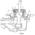
- Fig. 1 the shift lever bearing 1 for a shift lever 2 is shown.
- the shift lever bearing 1 normally has a so-called dome 3, in which the articulated ball 4 of the shift lever 2 is pivotably mounted in a corresponding plastic bearing arrangement 5.
- a further hat sleeve part 12 which likewise has a radial slot 13, is placed on the first hat sleeve part 6 in a latched manner, the second hat sleeve part 12 being rotatable radially with respect to the first hat sleeve part 6 by approximately 90 degrees is.
- the angle of rotation between the two hat collar parts 6 and 12 can be limited by a cam 14 projecting inwards on the second hat collar part 12 and a recess 15 provided on the first hat collar part 6.
- locking knobs 16 and locking recesses 17 arranged on adjoining surfaces of the hat cuff parts 6 and 12 can the two hat collar parts 6 and 12 be locked into a structural unit, the locking knobs 16 with the locking recesses 17 also defining the end positions of the rotation of the two components in relation to one another. Both the lateral surfaces and the base surfaces can be selected as adjoining surfaces.
- the transport and adjustment lock can also be designed such that a positive locking of the shift lever 2 in another, possibly more appropriate for the shift setting, here in the position for 1st gear at one double H circuit diagram, indicated in dash-dot lines, is possible.
- a correspondingly modified radial slot 9 'with resilient retaining tongues 10' and on the other hat sleeve part 12 'a different slot shape 18 with a locking surface 19 are required only in the one sleeve part 6'.
- the locking and rotation of both hat cuff parts 6 'and 12' is carried out in the same manner as that described in connection with Figures 2 to 5.
Landscapes
- Engineering & Computer Science (AREA)
- General Engineering & Computer Science (AREA)
- Mechanical Engineering (AREA)
- Chemical & Material Sciences (AREA)
- Combustion & Propulsion (AREA)
- Transportation (AREA)
- Arrangement Or Mounting Of Control Devices For Change-Speed Gearing (AREA)
- Gasket Seals (AREA)
Description
Die Erfindung bezieht sich auf eine Transport- und Einstellsicherung für den Schalthebel eines Wechselgetriebes, insbesondere für Kraftfahrzeuge, der im Oberbegriff des Patentanspruches 1 erläuterten Art.The invention relates to a transport and adjustment lock for the gear lever of a change gear, especially for motor vehicles, of the type explained in the preamble of
Aus der DE-OS 27 00 976 ist eine Diebstahlsicherung für ein Kraftfahrzeug bekannt, bei dem für den Schalthebel eines Wechselgetriebes, insbesondere eines Kraftfahrzeuges eine mit dem Dom der Schalthebellagerung verrastbare Hutmanschette vorgesehen ist, die durch Verdrehen in eine Sperrstellung bringbar ist, in der jede Bewegung des Schalthebels unterbunden ist.From DE-OS 27 00 976 an anti-theft device for a motor vehicle is known, in which a lockable with the dome of the gear lever bearing hat sleeve is provided for the shift lever of a gearbox, in particular a motor vehicle, which can be brought into a locked position by rotating, in which each Movement of the shift lever is prevented.
Die Hutmanschette, wie sie in den Figuren 5 bis 7 dieser Schrift gezeigt ist, wirkt hierbei über Bolzen auf an der Schalthebellagerung schwenkbar angeordnete Sperrhebel ein, um diese nach innen in eine den Schalthebel formschlüssig blockierende Sperrstellung zu drängen. In dieser Sperrstellung muß die Hutmanschette durch einen Schließzylinder in ihrer verdrehten Lage festgehalten werden.The hat cuff, as shown in FIGS. 5 to 7 of this document, acts here via bolts on locking levers pivotably arranged on the shift lever bearing, in order to urge them inward into a locking position which positively blocks the shift lever. In this locked position, the hat cuff must be held in its twisted position by a locking cylinder.
Diese bekannte Vorrichtung zum Blockieren eines Schalthebels in einer Sperrstellung ist somit verhältnismäßig aufwendig und teuer in der Herstellung und schwierig in der Montage und kann dementsprechend nicht als einfach aufsetzbare und abnehmbare Transport- und Einstellsicherung verwendet werden.This known device for blocking a shift lever in a locked position is therefore relatively complex and expensive to manufacture and difficult to assemble and can accordingly not be used as an easily attachable and removable transport and adjustment lock.
In der Kraftfahrzeugindustrie ist es bereits bekannt, bei der Montage des Wechselgetriebes im Kraftfahrzeug den Schalthebel am Wechselgetriebe durch eine Transport- und Einstellsicherung in einer bestimmten Stellung festzuhalten, damit bei der Herstellung der Verbindungen vom äußeren Schaltgestänge zum inneren Schaltgestänge des Wechselgetriebes ein einwandfreies Zusammenspiel sichergestellt wird. Diese Transport- und Einstellsicherung war bisher in Form eines einfachen, aufrastbaren Hutmanschettenteiles ausgebildet, das den Schalthebel in einem Radialschlitz über federnde Haltezungen in seiner Neutralstellung festgelegt hatte.In the motor vehicle industry, it is already known to hold the shift lever on the change gear in a certain position during the assembly of the change gear in the motor vehicle by means of a transport and setting lock, so that a perfect interaction is ensured in the production of the connections from the outer shift linkage to the inner shift linkage of the change gear . This transport and adjustment lock was previously designed in the form of a simple, snap-on hat sleeve part, which had fixed the shift lever in a radial slot via resilient retaining tongues in its neutral position.
Im rauhen Transport- und Montagebetrieb ist es immer wieder dazu gekommen, daß der Schalthebel durch Stöße ungewollt aus seiner bestimmten Stellung herausbewegt wurde, da die federnden Haltezungen keine formschlüssige Blockierung des Schalthebels ermöglichten.In rough transport and assembly operations, it has repeatedly happened that the shift lever was unintentionally moved out of its specific position by bumps, since the resilient retaining tongues did not allow any positive locking of the shift lever.
Die Aufgabe der Erfindung ist es daher, eine Transport- und Einstellsicherung für den Schalthebel eines Wechselgetriebes, insbesondere für Kraftfahrzeuge, der im Oberbegriff des Patentanspruches 1 erläuterten Art derart zu verbessern, daß eine formschlüssige Festlegung des Schalthebels in einer vorbestimmten Stellung mit einfachen Maßnahmen ermöglicht wird und dennoch die erforderliche Vorrichtung einen geringen Bauaufwand aufweist und einfach aufgesetzt und abgenommen werden kann.The object of the invention is therefore to improve a transport and setting lock for the gear lever of a change gear, especially for motor vehicles, of the type explained in the preamble of
Gemäß der Erfindung wird diese Aufgabe gelöst, indem bei einer Transport- und Einstellsicherung für den Schalthebel eines Wechselgetriebes, insbesondere für Kraftfahrzeuge, der im Oberbegriff des Patentanspruches erläuterten Art die im Kennzeichenteil des Patentanspruches 1 aufgezeigten Merkmale vorgesehen werden.According to the invention, this object is achieved in that the features indicated in the characterizing part of
In den Ansprüchen 2 und 3 sind zweckmäßige Einzelheiten der erfindungsgemäßen Vorrichtung erläutert. In Anspruch 4 ist eine weitere Ausführungsform der Erfindung erläutert.Expedient details of the device according to the invention are explained in
Dadurch, daß mit dem ersten Hutmanschettenteil, das auf dem Dom der Schalthebellagerung verrastbar aufsetzbar ist und das den Schalthebel bereits in einem Radialschlitz zwischen federnden Haltezungen in einer vorbestimmten Stellung festhält, ein zweites Hutmanschettenteil verrastet ist, das gegenüber dem ersten Manschettenteil um etwa 90 Grad verdrehbar ist und hierdurch den Schalthebel voll formschlüssig in seiner vorbestimmten Stellung festhält, wird jedes unerwünschte Heraustreten des Schalthebels aus seiner vorbestimmten Stellung während des Transportes oder während der Montage und/oder Einstellung sicher vermieden.Characterized in that with the first hat cuff part, which can be placed on the dome of the shift lever bearing and which holds the shift lever in a radial slot between resilient retaining tongues in a predetermined position, a second hat cuff part is locked, which can be rotated by about 90 degrees with respect to the first cuff part is and thereby holds the shift lever fully positively in its predetermined position, any undesired emergence of the shift lever from its predetermined position during transport or during assembly and / or adjustment is safely avoided.
Dadurch, daß am zweiten Hutmanschettenteil ein Vorsprung vorgesehen ist, der in eine Ausnehmung im ersten Hutmanschettenteil eingreift, kann dessen Verdrehwinkel festgelegt werden.Characterized in that a projection is provided on the second hat cuff part which engages in a recess in the first hat cuff part, the angle of rotation thereof can be determined.
Durch entsprechende Rastnoppen und Rastmulden an den beiden Hutmanschettenteilen können die beiden Bauteile miteinander verrastet und in ihren jeweiligen Endlagen fixiert werden.The two components can be locked together and fixed in their respective end positions by means of corresponding locking knobs and locking recesses on the two hat cuff parts.
Durch eine geänderte Ausführung des Radialschlitzes mit den federnden Haltezungen am einen Hutmanschettenteil in Verbindung mit einer anderen Schlitzform mit einer Sperrfläche am anderen Hutmanschettenteil kann der Schalthebel auch in einer anderen vorbestimmten Stellung, die für die Einstellung der Schaltung günstiger ist, z.B. in der Stellung für den 1. Gang, festgelegt werden.By changing the design of the radial slot with the resilient retaining tongues on one hat cuff part in connection with another slot shape with a locking surface on the other hat cuff part, the shift lever can also be in a different predetermined position, which is more favorable for setting the circuit, e.g. in the 1st gear position.
Die Erfindung wird anhand von in den beiliegenden Zeichnungen gezeigten Ausführungsformen näher erläutert. Es zeigt:
- Fig. 1
- einen vertikalen Schnitt durch die Schalthebellagerung eines Wechselgetriebes mit der aufgesetzten Transport- und Einstellsicherung;
- Fig. 2
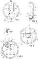
- eine Draufsicht auf die Transport- und Einstellsicherung nach Fig. 1 in der Stellung der beiden verrasteten Hutmanschettenteile zum Aufsetzen auf die Schalthebellagerung;
- Fig. 3
- einen vertikalen Schnitt entlang der. Linie III-III in Fig. 2;
- Fig. 4
- einen Schnitt entlang der Linie IV-IV in Fig. 2;
- Fig. 5
- eine Draufsicht auf die beiden Hutmanschettenteile in formschlüssiger Sperrstellung und
- Fig. 6
- eine Draufsicht auf eine weitere Ausführungsform der Erfindung.
- Fig. 1
- a vertical section through the shift lever bearing of a change gear with the attached transport and adjustment lock;
- Fig. 2
- a plan view of the transport and adjustment lock according to Figure 1 in the position of the two latched hat cuff parts for placement on the gear lever bearing.
- Fig. 3
- a vertical section along the. Line III-III in Fig. 2;
- Fig. 4
- a section along the line IV-IV in Fig. 2;
- Fig. 5
- a plan view of the two hat cuff parts in a positive locking position and
- Fig. 6
- a plan view of a further embodiment of the invention.
In Fig. 1 ist die Schalthebellagerung 1 für einen Schalthebel 2 gezeigt. Die Schalthebellagerung 1 weist normalerweise einen sogenannten Dom 3 auf, in dem die Gelenkkugel 4 des Schalthebels 2 in einer entsprechenden Kunststofflageranordnung 5 schwenkbar gelagert ist.In Fig. 1, the shift lever bearing 1 for a
Zur Transport- und Einstellsicherung des Schalthebels 2 des Wechselgetriebes, in einer bestimmten Stellung war es bereits bekannt, ein Hutmanschettenteil 6 auf den Dom 3 aufzusetzen und über eine Nase 7 in einer Ausnehmung 8 am Dom 3 zu verrasten, wobei das Hutmanschettenteil einen Radialschlitz 9 aufwies, der zur Mitte des Hutmanschettenteiles 6 hin von zwei federnden Haltezungen 10 begrenzt wurde.To secure the transport lever and setting of the
Zum Aufsetzen des Hutmanschettenteiles 6 muß dieser zunächst über den Radialschlitz 9 auf den Schalthebel 2 aufgesetzt werden, bis durch Zurückweichen der federnden Haltezungen 10 die vorbestimmte Stellung erreicht wird und danach wird das Hutmanschettenteil 6 nach unten auf den Dom 3 gedrückt und mittels der Nase 7 in der Ausnehmung 8 gegen Verdrehen festgelegt.To put on the
Obwohl die federnden Haltezungen 10 bereits eine Festlegung für den Schalthebel 2 in einer vorbestimmten Stellung sichergestellt haben, ist es im rauhen Transport- und Montagebetrieb doch immer wieder dazu gekommen, daß durch eine ungewollt am Schalthebel 2 einwirkende Kraft der Schalthebel 2 aus seiner vorbestimmten Stellung herausbewegt wurde.Although the resilient retaining
Wurde diese Verlagerung des Schalthebels 2 nicht registriert, so konnte es beim Verbinden des äußeren Schaltgestänges mit dem inneren Schaltgestänge im Wechselgetriebe zu einer Fehlmontage kommen, die Schaltstörungen mit sich brachte.If this shifting of the
Wie aus den Figuren 2 bis 5 zu ersehen ist, wird gemäß der Erfindung ein weiteres Hutmanschettenteil 12, das gleichfalls einen Radialschlitz 13 aufweist auf das erste Hutmanschettenteil 6 verrastet aufgesetzt, wobei das zweite Hutmanschettenteil 12 radial gegenüber dem ersten Hutmanschettenteil 6 um etwa 90 Grad verdrehbar ist.As can be seen from FIGS. 2 to 5, according to the invention a further
Der Verdrehwinkel zwischen den beiden Hutmanschettenteilen 6 und 12 kann durch einen am zweiten Hutmanschettenteil 12 nach innen ragenden Nocken 14 und eine am ersten Hutmanschettenteil 6 vorgesehene Ausnehmung 15 begrenzt werden.The angle of rotation between the two
Durch an aneinanderliegenden Flächen der Hutmanschettenteile 6 und 12 angeordneten Rastnoppen 16 und Rastmulden 17 können die beiden Hutmanschettenteile 6 und 12 zu einer Baueinheit verrastet werden, wobei die Rastnoppen 16 mit den Rastmulden 17 auch die Endlagen der Verdrehung der beiden Bauteile zueinander einrastend festlegen. Als aneinanderliegende Flächen können sowohl die Mantelflächen als auch die Bodenflächen gewählt werden.By means of
Durch das zusätzliche zweite Hutmanschettenteil 12 kann somit durch eine Drehung um etwa 90 Grad eine völlige formschlüssige Festlegung des Schalthebels 2 in seiner vorbestimmten Stellung, hier in der Neutralstellung für den Transport, die Montage und die Einstellung festgelegt werden.By means of the additional second
Wie aus Fig. 6 zu ersehen ist, kann die Transport- und Einstellsicherung auch derart ausgebildet werden, daß eine formschlüssige Festlegung des Schalthebels 2 in einer anderen, für die Schaltungseinstellung ggf. zweckmäßigeren Stellung, hier in der Stellung für den 1. Gang bei einem in Strich-Punkt-Linien angedeuteten Doppel-H-Schaltschema, möglich ist.As can be seen from Fig. 6, the transport and adjustment lock can also be designed such that a positive locking of the
Hierzu sind lediglich in dem einen Hutmanschettenteil 6′ ein entsprechend veränderter Radialschlitz 9′ mit federnden Haltezungen 10′ und an dem anderen Hutmanschettenteil 12′ eine andere Schlitzform 18 mit einer Sperrfläche 19 erforderlich. Die Verrastung und Verdrehung beider Hutmanschettenteile 6′ und 12′ erfolgt in der gleichen Art und Weise, wie sie in Verbindung mit den Figuren 2 bis 5 beschrieben wurde.For this purpose, a correspondingly modified radial slot 9 'with resilient retaining tongues 10' and on the other hat sleeve part 12 'a
Claims (4)
- Transportation and adjustment protecting means for the gear-shift lever (2) of a transmission, in particular for motor vehicles, with a cap-type packing which is applied to the dome (3) of the gear-shift lever mounting(l) and secures the gear-shift lever in a specific arrested position, characterised in that a first cap-type packing member (6) can be applied in an engaged manner to the dome (3) of the gear-shift lever mounting (1) in a location which is secured against rotation by a nose (7) and a recess (8) on the dome (3) and secures the gear-shift lever (2) in a specific position in a radial slot (9) between resilient holding tongues (10) and a second cap-type packing member (12) engages with the first cap-type packing member (6), similarly has a radial slot (13), is rotatable relative to the first cap-type packing member (6) and, in this rotated location, secures the gear-shift lever (2) completely positively in its predetermined position.
- Transportation and adjustment protecting means according to claim 1, characterised in that the second cap-type packing member (12) is limited in its angle of rotation by a projection (14) which projects inwardly from its internal periphery and meshes in a recess (15) in the first cap-type packing member (5).
- Transportation and adjustment protecting means according to claims 1 and 2, characterised in that inwardly projecting catch knobs (16) which co-operate with corresponding catch cavities (17) are provided on contiguous faces, the circumferential or base faces, on the second cap-type packing member (12) and on the first cap-type packing member (6), in order to hold the two cap-type packing members (6 and 12) together in an engaging manner and to fix the rotational end locations thereof.
- Transportation and adjustment protecting means according to claims 1 to 3, characterised in that a radial slot (9′) adapted to a specific position (first gear speed) with resilient tongues (10′) securing the gear-shift lever (2) is provided on one cap-type packing member (6′) and a different slot shape (18) which positively secures the gear-shift lever (2) via an arresting face (19) after a rotation is provided on the second cap-type packing member (12′).
Applications Claiming Priority (2)
| Application Number | Priority Date | Filing Date | Title |
|---|---|---|---|
| DE4029789A DE4029789C1 (en) | 1990-09-20 | 1990-09-20 | |
| DE4029789 | 1990-09-20 |
Publications (2)
| Publication Number | Publication Date |
|---|---|
| EP0476396A1 EP0476396A1 (en) | 1992-03-25 |
| EP0476396B1 true EP0476396B1 (en) | 1994-07-06 |
Family
ID=6414617
Family Applications (1)
| Application Number | Title | Priority Date | Filing Date |
|---|---|---|---|
| EP91114641A Expired - Lifetime EP0476396B1 (en) | 1990-09-20 | 1991-08-30 | Securing device for transporting and mounting of a gearshift lever of a gearbox in particular for motor vehicles |
Country Status (3)
| Country | Link |
|---|---|
| US (1) | US5105676A (en) |
| EP (1) | EP0476396B1 (en) |
| DE (2) | DE4029789C1 (en) |
Families Citing this family (8)
| Publication number | Priority date | Publication date | Assignee | Title |
|---|---|---|---|---|
| DE4127730A1 (en) * | 1991-08-22 | 1993-03-04 | Ford Werke Ag | SHIFT LEVER BEARING FOR TRANSMISSION OF MOTOR VEHICLES |
| JPH07151224A (en) * | 1993-11-30 | 1995-06-13 | Fuji Kiko Co Ltd | Control device for automatic speed change gear |
| FR2775748B1 (en) * | 1998-03-06 | 2000-04-07 | United Parts France Sa | DEVICE FOR LOCKING A SPEED CHANGE LEVER IN A SPEED CONTROL ASSEMBLY FOR A MOTOR VEHICLE |
| DE59802447D1 (en) * | 1998-09-01 | 2002-01-24 | Ford Global Tech Inc | Transport and adjustment lock for a gear lever or selector lever of a transmission of a motor vehicle |
| KR100456892B1 (en) * | 2002-08-13 | 2004-11-10 | 현대자동차주식회사 | transmission gear shift lever device having variable select lever ratio |
| DE102007004455A1 (en) * | 2007-01-30 | 2008-07-31 | GM Global Technology Operations, Inc., Detroit | Shift lever arrangement for motor vehicle, has detachable auxiliary connection, which is provided for temporary fastening of shift lever with shift lever housing during mounting of shift lever arrangement in motor vehicle |
| CN104163101A (en) * | 2014-07-31 | 2014-11-26 | 法可赛(太仓)汽车配件有限公司 | Vibration resisting and noise lowering gear unit |
| FR3042014A1 (en) * | 2015-10-05 | 2017-04-07 | Peugeot Citroen Automobiles Sa | DEVICE FOR LOCKING A SHIFT LEVER IN A MOTOR VEHICLE SPEED CONTROL BLOCK |
Family Cites Families (6)
| Publication number | Priority date | Publication date | Assignee | Title |
|---|---|---|---|---|
| DE1766859U (en) * | 1958-03-07 | 1958-05-14 | Kloeckner Humboldt Deutz Ag | DEVICE FOR SHUTDING INDIVIDUAL GEAR RATIO LEVELS OF A MANUAL TRANSMISSION OF VEHICLES. |
| DE1165433B (en) * | 1960-05-05 | 1964-03-12 | Oscar Adolf Wallmark | Gear lever locking device for motor vehicles |
| US3665776A (en) * | 1971-04-26 | 1972-05-30 | Superior Industries | Vehicle gear shift mechanism |
| DE2700976A1 (en) * | 1977-01-12 | 1978-07-13 | Erich Dr Brendl | Vehicle anti-theft device - has two part gear selector lever joined by security lock |
| GB2152454A (en) * | 1984-01-07 | 1985-08-07 | Stephen Philip Wilson | Gear level locking device |
| DE3807508C1 (en) * | 1988-03-08 | 1989-04-20 | Adam Opel Ag, 6090 Ruesselsheim, De | Gearshift device for a motor vehicle gearbox |
-
1990
- 1990-09-20 DE DE4029789A patent/DE4029789C1/de not_active Expired - Lifetime
-
1991
- 1991-06-07 US US07/711,842 patent/US5105676A/en not_active Expired - Lifetime
- 1991-08-30 DE DE59102115T patent/DE59102115D1/en not_active Expired - Lifetime
- 1991-08-30 EP EP91114641A patent/EP0476396B1/en not_active Expired - Lifetime
Also Published As
| Publication number | Publication date |
|---|---|
| US5105676A (en) | 1992-04-21 |
| EP0476396A1 (en) | 1992-03-25 |
| DE59102115D1 (en) | 1994-08-11 |
| DE4029789C1 (en) | 1992-02-13 |
Similar Documents
| Publication | Publication Date | Title |
|---|---|---|
| EP0731885B1 (en) | Gear shift device | |
| DE3501262C1 (en) | Pull lock that can be locked in open position | |
| EP0903518B1 (en) | Shift device for a vehicle transmission | |
| DE3514497A1 (en) | PROTECTIVE CAP FOR CYLINDRICAL PARTS, ESPECIALLY FOR A BOLT GUIDE OF A PART COVER DISC BRAKE | |
| DE2949354A1 (en) | DEVICE FOR PREVENTING SWITCHING ERRORS IN MANUAL GEARBOXES FOR VEHICLES | |
| DE1655013C3 (en) | Switching and locking device for a vehicle change gearbox | |
| WO1986000967A1 (en) | Gear shifting device | |
| DE2239853C3 (en) | Holding device for exterior rearview mirrors of motor vehicles or the like | |
| EP0476396B1 (en) | Securing device for transporting and mounting of a gearshift lever of a gearbox in particular for motor vehicles | |
| DE102017104173A1 (en) | RELEASE WITH TWO DIFFERENT RATES FOR SELECTABLE CLUTCH CLASPS | |
| DE4024484C2 (en) | Floating caliper for partial pad disc brake with locked housing retaining spring | |
| DE2942789A1 (en) | PERMUTATION LOCK | |
| DE4141007A1 (en) | CABLE CONNECTOR FOR A STEERING LOCKING DEVICE | |
| DE19729767A1 (en) | Gear change device for mechanical multi-stage gearwheel change gear for motor car | |
| DE19914198B4 (en) | Reverse locking device on a manual transmission | |
| AT405108B (en) | MANUAL GEARBOX WITH GEARBOX SLIDING FORK | |
| DE19511510C1 (en) | Cam disc arrangement for gear shifting gate | |
| DE102007037521A1 (en) | Circuit arrangement for selecting and shifting a gear in a manual transmission of a vehicle | |
| EP2425156B1 (en) | Retaining device, particularly for a shifter shaft | |
| DE4110012C1 (en) | Road vehicle manual gearchange - uses two blocking cams to avoid inadvertent engagement of reverse gear | |
| EP2064091B1 (en) | Steering column module | |
| DE102008017542B4 (en) | Fahrbereichswählhebelbaueinheit | |
| DE4323648C1 (en) | Locking device for shift rods in change gearboxes of motor vehicles | |
| DE102011004016A1 (en) | Switching device for a vehicle transmission | |
| DE2227561C2 (en) | Anti-theft device on the steering column of a motor vehicle |
Legal Events
| Date | Code | Title | Description |
|---|---|---|---|
| PUAI | Public reference made under article 153(3) epc to a published international application that has entered the european phase |
Free format text: ORIGINAL CODE: 0009012 |
|
| 17P | Request for examination filed |
Effective date: 19920128 |
|
| AK | Designated contracting states |
Kind code of ref document: A1 Designated state(s): DE FR GB IT SE |
|
| 17Q | First examination report despatched |
Effective date: 19930719 |
|
| GRAA | (expected) grant |
Free format text: ORIGINAL CODE: 0009210 |
|
| AK | Designated contracting states |
Kind code of ref document: B1 Designated state(s): DE FR GB IT SE |
|
| PG25 | Lapsed in a contracting state [announced via postgrant information from national office to epo] |
Ref country code: IT Free format text: LAPSE BECAUSE OF FAILURE TO SUBMIT A TRANSLATION OF THE DESCRIPTION OR TO PAY THE FEE WITHIN THE PRE;WARNING: LAPSES OF ITALIAN PATENTS WITH EFFECTIVE DATE BEFORE 2007 MAY HAVE OCCURRED AT ANY TIME BEFORE 2007. THE CORRECT EFFECTIVE DATE MAY BE DIFFERENT FROM THE ONE RECORDED.SCRIBED TIME-LIMIT Effective date: 19940706 Ref country code: FR Effective date: 19940706 |
|
| GBT | Gb: translation of ep patent filed (gb section 77(6)(a)/1977) |
Effective date: 19940704 |
|
| REF | Corresponds to: |
Ref document number: 59102115 Country of ref document: DE Date of ref document: 19940811 |
|
| PG25 | Lapsed in a contracting state [announced via postgrant information from national office to epo] |
Ref country code: SE Effective date: 19941006 |
|
| EN | Fr: translation not filed | ||
| PLBE | No opposition filed within time limit |
Free format text: ORIGINAL CODE: 0009261 |
|
| STAA | Information on the status of an ep patent application or granted ep patent |
Free format text: STATUS: NO OPPOSITION FILED WITHIN TIME LIMIT |
|
| 26N | No opposition filed | ||
| REG | Reference to a national code |
Ref country code: GB Ref legal event code: 746 Effective date: 19970723 |
|
| REG | Reference to a national code |
Ref country code: GB Ref legal event code: IF02 |
|
| PGFP | Annual fee paid to national office [announced via postgrant information from national office to epo] |
Ref country code: DE Payment date: 20100831 Year of fee payment: 20 |
|
| PGFP | Annual fee paid to national office [announced via postgrant information from national office to epo] |
Ref country code: GB Payment date: 20100708 Year of fee payment: 20 |
|
| REG | Reference to a national code |
Ref country code: DE Ref legal event code: R071 Ref document number: 59102115 Country of ref document: DE |
|
| REG | Reference to a national code |
Ref country code: DE Ref legal event code: R071 Ref document number: 59102115 Country of ref document: DE |
|
| REG | Reference to a national code |
Ref country code: GB Ref legal event code: PE20 Expiry date: 20110829 |
|
| PG25 | Lapsed in a contracting state [announced via postgrant information from national office to epo] |
Ref country code: GB Free format text: LAPSE BECAUSE OF EXPIRATION OF PROTECTION Effective date: 20110829 |
|
| PG25 | Lapsed in a contracting state [announced via postgrant information from national office to epo] |
Ref country code: DE Free format text: LAPSE BECAUSE OF EXPIRATION OF PROTECTION Effective date: 20110831 |