EP0475840B1 - Linsentubus zum automatischen Fokussieren - Google Patents
Linsentubus zum automatischen Fokussieren Download PDFInfo
- Publication number
- EP0475840B1 EP0475840B1 EP91402416A EP91402416A EP0475840B1 EP 0475840 B1 EP0475840 B1 EP 0475840B1 EP 91402416 A EP91402416 A EP 91402416A EP 91402416 A EP91402416 A EP 91402416A EP 0475840 B1 EP0475840 B1 EP 0475840B1
- Authority
- EP
- European Patent Office
- Prior art keywords
- lens
- holding member
- coil
- outer shell
- lens holding
- Prior art date
- Legal status (The legal status is an assumption and is not a legal conclusion. Google has not performed a legal analysis and makes no representation as to the accuracy of the status listed.)
- Expired - Lifetime
Links
Images



Classifications
-
- G—PHYSICS
- G02—OPTICS
- G02B—OPTICAL ELEMENTS, SYSTEMS OR APPARATUS
- G02B7/00—Mountings, adjusting means, or light-tight connections, for optical elements
- G02B7/02—Mountings, adjusting means, or light-tight connections, for optical elements for lenses
- G02B7/04—Mountings, adjusting means, or light-tight connections, for optical elements for lenses with mechanism for focusing or varying magnification
-
- G—PHYSICS
- G02—OPTICS
- G02B—OPTICAL ELEMENTS, SYSTEMS OR APPARATUS
- G02B7/00—Mountings, adjusting means, or light-tight connections, for optical elements
- G02B7/02—Mountings, adjusting means, or light-tight connections, for optical elements for lenses
- G02B7/04—Mountings, adjusting means, or light-tight connections, for optical elements for lenses with mechanism for focusing or varying magnification
- G02B7/10—Mountings, adjusting means, or light-tight connections, for optical elements for lenses with mechanism for focusing or varying magnification by relative axial movement of several lenses, e.g. of varifocal objective lens
-
- H—ELECTRICITY
- H04—ELECTRIC COMMUNICATION TECHNIQUE
- H04N—PICTORIAL COMMUNICATION, e.g. TELEVISION
- H04N23/00—Cameras or camera modules comprising electronic image sensors; Control thereof
- H04N23/57—Mechanical or electrical details of cameras or camera modules specially adapted for being embedded in other devices
Definitions
- This invention relates to a novel lens barrel apparatus for automatic focusing, and more particularly to a lens barrel apparatus for automatic focusing which includes electromagnetic actuating means for moving a focusing lens and speed detecting means for detecting the speed of movement of the focusing lens.
- a lens barrel apparatus for a camera having an automatic focusing function normally includes actuating means for moving a focusing lens in a direction of an optic axis thereof and speed detecting means for detecting a speed of movement of the focusing lens.
- An actuator of the electromagnetically driving type including a coil and a magnet is employed comparatively frequently as the driving means while an electromagnetic sensor element including a coil and a magnet is employed comparatively frequently as the speed detecting means.
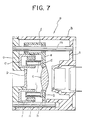
- Figs. 7 and 8 show an example of a lens barrel apparatus previously developed by the Applicant which includes such actuator and sensor element as described just above.
- the lens barrel apparatus generally denoted at a includes an outer shell b having a substantially prism-like profile elongated in a forward and rearward direction, and several lenses including a master lens c disposed in the inside of the outer shell b such that they have a common optic axis.
- the master lens c is held in a light passing hole formed at the center of a lens holding member d having a ring-like profile.
- a mounting arm e extends radially outwardly from a right upper portion of the lens holding member d and has a tubular bearing portion f formed integrally at an end portion thereof in parallel to the optic axis.
- a guide arm g extends radially outwardly from another portion of the lens holding member d remote from the mounting arm e with respect to the light passing hole and has a fork-shaped receiving portion h formed at an end thereof.
- a cylindrical coil core i is formed such that it extends forwardly from an inner circumferential edge of the light passing hole of the lens holding member d , and an actuating coil j is wound in a direction around the optic axis on the coil core i .
- the lens holding member d is supported on the sliding shaft m for movement in the direction of the optic axis under the guidance of the guide shaft n in the outer shell b . Accordingly, the master lens c is supported for movement on the lens holding member d in the forward and backward direction of the lens barrel apparatus a .
- a support member o is secured in an inwardly fitted condition to a forward end of the outer shell b , forwardly of the lens holding member d .
- a light passing hole is formed in the support member o forwardly in an opposing relationship to the master lens c , and a lens p is disposed in the light passing hole of the support member o .
- a yoke q is disposed on a face of the support member o opposing to the master lens c such that it surrounds the light passing hole of the support member o .
- the yoke q is formed as a unitary member of a metal material having a good permeability and includes a ring-shaped intermediate yoke portion, an inner yoke portion extending rearwardly from an inner circumferential edge of the intermediate yoke portion and an outer cylindrical yoke portion extending rearwardly from an outer circumferential edge of the intermediate yoke portion in a coaxial parallel relationship to the inner yoke portion.
- a lens barrel apparatus for automatic focussing comprising: an outer shell; a lens holding member holding a focusing lens thereon and mounted in said outer shell for movement in a direction of the optical axis of said focusing lens, the lens holding member including lens position detecting means for detecting the position of said focusing lens in the direction of the optical axis; an actuator including an actuating coil secured to one of said lens holding member and said outer shell and wound around a coil core, said actuator further including a magnet secured to the other of said lens holding member and said outer shell in a coaxial relationship with said actuating coil around the optical axis; and a detecting coil wound on said coil core in an overlapping relationship with said actuating coil for detecting the speed of movement of said focusing lens.
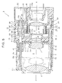
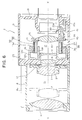
- a plurality of lenses 6, 7, 8, 9 and 10 each having a predetermined light controlling function are arranged in this order from the front in the outer shells 4 and 5 such that they have a single common optic axis X-X.
- the lenses 6 and 7 are positioned in the front outer shell 4 and constitute a zooming lens system while the other lenses 8, 9 and 10 are positioned in the rear outer shell 5 and constitute a focusing lens system.
- the lens 7 serves as a movable lens for zooming while the rear end lens 10 is a so-called master lens and serves as a movable lens for focusing.
- the zooming lens 7 is held in a zooming lens holding member 12 having a ring-like profile.
- the zooming lens holding member 12 has a tubular portion provided integrally on and extending forwardly from an inner circumferential edge thereof, and the zooming lens 7 is held in an inwardly fitted condition in the tubular portion of the zooming lens holding member 12.
- a guide arm 15 is formed integrally on and extends outwardly from a left lower portion of the zooming lens holding member 12, and a fork-shaped receiving portion 16 is formed at an end portion of the guide arm 15.
- the nut 14 secured to the mounting arm 13 of the zooming lens holding member 12 is screwed to a threaded portion of a front half portion of the output shaft 21 of the zooming motor 20 while the receiving portion 16 of the guide arm 15 is supported for sliding movement on a guide shaft 22 thereby to support the zooming lens holding member 12 for movement in the forward and rearward directions in the front outer shell 4.
- a motor accommodating chamber 19 is formed at a right upper portion of a rear end edge portion of the rear outer shell 5. and the zooming motor 20 is securely accommodated in the motor accommodating chamber 19.
- a passing hole 19a is formed in a front wall of the motor accommodating chamber 19. and the output shaft 21 of the zooming motor 20 extends through the passing hole 19a.
- the output shaft 21 of the zooming motor 20 has sufficient length to extend to a front end of the front outer shell 4, and a threaded groove is formed at a portion 21b (hereinafter referred to as “threaded shaft portion") that excludes a rear half portion 21a (hereinafter referred to as “sliding shaft portion”) adjacent the zooming motor 20 and an opposite end portion 21c.
- the threaded shaft portion 21a of the output shaft 21 extends substantially throughout the overall length in the radially projected rib 4a of the front outer shell 4 while the sliding shaft portion 21a is positioned at a right upper portion in the rear outer shell 5.
- the master lens 10 is held in a light passing hole 25a formed at the center of a master lens holding member 25 having a ring-like profile.
- a mounting arm 26 is formed integrally at and extends radially outwardly from a right upper portion of the master lens holding member 25, and a cylindrical bearing portion 27 is formed integrally on and extends axially forwardly from the mounting arm 26.
- a pair of bearing metal members 28 are secured in a force-fitted condition at the opposite front and rear ends of an axial hole of the bearing portion 27.
- a guide arm 29 is formed integrally at and extends radially outwardly from a left lower portion of the master lens holding member 25 remote from the mounting arm 26, and a fork-shaped receiving portion 30 is formed at an end portion of the guide arm 29.
- the bearing metal members 28 of the mounting arm 26 of the master lens holding member 25 are supportcd for sliding movement on the sliding shaft portion 21a of the output shaft 21 of the zooming motor 20 while the receiving portion 30 of the guide arm 29 of the master lens holding member 25 is supported for sliding movement on the guide shaft 22 thereby to allow the master lens holding member 25 to be moved in the forward or rearward direction in the rear outer shell 5.
- the nut 14 of the mounting arm 13 of the zooming lens holding member 12 is held in screwed engagement with the threaded shaft portion 21b of the output shaft 21 of the zooming motor 20 while the receiving portion 16 of the guide shaft 15 of the zooming lens holding member 12 is supported for sliding movement on the guide shaft 22 thereby to allow the zooming lens holding member 12 to be moved in the forward or rearward direction in the front outer shell 4.
- the zooming motor 20 rotates, the output shaft 21 is rotated and consequently the nut 15 is fed in the forward or rearward direction to move the zooming lens holding member 12 in the forward or rearward direction.
- the yoke member 33 is formed as a unitary member from a metal material having a high permeability and has an intermediate yoke portion 33a having a substantially ring-like profile, a cylindrical inner yoke portion 33b extending rearwardly from an inner circumferential edge of the intermediate yoke portion 33a, and an inner yoke portion 33c extending rearwardly from an outer circumferential edge of the intermediate yoke portion 33a in parallel to the inner yoke portion 33b.
- the inner yoke portion 33b of the yoke member 33 is secured in a force-fitted condition from the rear on the lens tube 23b of the support wall 23 while the intermediate yoke portion 33a is held in contact with and secured to a rear face of the support wall 23.
- the actuating coil 35 is wound on the coil core 31 of the master lens holding member 25 and is positioned between the inside yoke portion 33b of the yoke member 33 and the magnet 34, with a small gap left therebetween.
- speed detecting means 36 is provided for detecting a speed of movement of the master lens holding member 25 in order to control such speed.
- the speed detecting means 36 is constituted from the magnet 34 depending from the support wall 23 and a detecting coil 37 wound on the coil bobbin 31 of the master lens holding member 25.
- the actuating coil 35 is wound on the coil core 31 of the master lens holding member 25 as described above, and the detecting coil 37 is wound in an overlapping relationship on the actuating coil 35.
- the detecting coil 37 is moved together therewith, and consequently, an electric current corresponding to a speed of such movement is induced in and flows through the detecting coil 37.
- a speed of movement of the master lens holding member 25 is detected by detecting a magnitude of such electric current.
- the speed of movement of the master lens holding member 25 is controlled so that it may be made low so that no hunting takes place upon focusing.
- a position detecting means 38 is provided for detecting a position of the master lens holding member 25, or in other words, a position of the master lens 10.
- the position detecting means 38 includes a magnet 39 having an inclined plane, mounted on the master lens holding member 25, and a Hall effect element 41 mounted on the rear wall 18 of the rear outer shell 5.
- the inclined plane magnet 39 has a rectangular sectional shape in a direction perpendicular to a longitudinal direction thereof, and a front end portion thereof is supported in an embedded condition on a detecting member mounting portion 40 integrally formed on the left lower guide arm 29 provided on the master lens holding member 25.
- a front half portion 39a of a face of the inclined plane magnet 39 remote from the optic axis X-X is inclined such that it approaches the optic axis X-X toward its front end as particularly shown in Fig. 6.
- the position detecting means may be replaced by a potentiometer.
- the detecting coil 37 in the embodiment described above is of the type wherein it is wound in an overlapping relationship on the actuating coil 35 wound on the coll bobbin 31, the actuating coil 35 may alternatively be wound in an overlapping relationship on the detecting coil 37 wound on the coil core 31.
- the actuating coil 35 and the detecting coil 37 are mounted on a movable side member (master lens holding member 25) while the magnet 34 is mounted on a fixed side member (support wall 23)
- the actuating coil 35 and the detecting coil 37 may alternatively be mounted on a fixed side member while the magnet 34 is mounted on a movable side member. In the latter case, since the coils 35 and 37 are wound on the fixed side member, wiring to the coil is facilitated.
- the present invention is applied to a lens barrel apparatus for a video camera in the embodiment described above, the application of the present invention is not limited only to such arrangement, and the present invention can be applied widely as a lens barrel apparatus for a common camera such as, for example, a lens barrel apparatus for a still camera.
Landscapes
- Physics & Mathematics (AREA)
- General Physics & Mathematics (AREA)
- Optics & Photonics (AREA)
- Engineering & Computer Science (AREA)
- Multimedia (AREA)
- Signal Processing (AREA)
- Lens Barrels (AREA)
Claims (3)
- Linsentubuseinrichtung zum automatischen Fokussieren, bestehend aus:
einer äußeren Schale (4, 5),
einem eine Fokussierungslinse (10) haltenden und in der äußeren Schale in Richtung einer optischen Achse der Fokussierungslinse bewegbar befestigten Linsenhalteteil (25-30) mit einer Linsenposition-Detektoreinrichtung (38-40) zum Detektieren der Position der Fokussierungslinse in Richtung der optischen Achse,
einer Betätigungseinrichtung (32) mit einer auf dem Linsenhalteteil (25-30) oder der äußeren Schale (4, 5) befestigten und um einen Spulenkern (31) gewickelten Betätigungsspule (35) und mit einem auf der äußeren Schale (4, 5) bzw. dem Linsenhalteteil (25-30) koaxial zu der die optische Achse umgebenden Betätigungsspule (35) befestigten Magneten (34), und
einer um den Spulenkern (31) in überlappender Relation zur Betätigungsspule (35) gewickelten Detektorspule (37) zum Detektieren der Bewegungsgeschwindigkeit der Fokussierungslinse. - Linsentubuseinrichtung zum automatischen Fokussieren nach Anspruch 1, wobei die Betätigungsspule (35) als eine innere Lage auf dem Spulenkern (31) und die Detektorspule (37) zum Detektieren der Bewegungsgeschwindigkeit der Fokussierungslinse (110) als eine äußere Lage auf die Betätigungsspule gewickelt ist.
- Linsentubuseinrichtung zum automatischen Fokussieren nach Anspruch 1, wobei das Linsenhalteteil (25-30) eine Linsenhalteeinrichtung (25) zum Halten der Fokussierungslinse (10) und einen als Spulenkern dienenden Spulenkernabschnitt (31) aufweist.
Applications Claiming Priority (2)
| Application Number | Priority Date | Filing Date | Title |
|---|---|---|---|
| JP239447/90 | 1990-09-10 | ||
| JP2239447A JPH04119306A (ja) | 1990-09-10 | 1990-09-10 | カメラ用レンズ鏡筒 |
Publications (2)
| Publication Number | Publication Date |
|---|---|
| EP0475840A1 EP0475840A1 (de) | 1992-03-18 |
| EP0475840B1 true EP0475840B1 (de) | 1995-07-19 |
Family
ID=17044911
Family Applications (1)
| Application Number | Title | Priority Date | Filing Date |
|---|---|---|---|
| EP91402416A Expired - Lifetime EP0475840B1 (de) | 1990-09-10 | 1991-09-10 | Linsentubus zum automatischen Fokussieren |
Country Status (6)
| Country | Link |
|---|---|
| US (1) | US5220461A (de) |
| EP (1) | EP0475840B1 (de) |
| JP (1) | JPH04119306A (de) |
| KR (1) | KR100195313B1 (de) |
| DE (1) | DE69111344T2 (de) |
| HK (1) | HK1007802A1 (de) |
Families Citing this family (34)
| Publication number | Priority date | Publication date | Assignee | Title |
|---|---|---|---|---|
| JPH04166906A (ja) * | 1990-10-31 | 1992-06-12 | Sony Corp | レンズ鏡筒の初期位置検出装置 |
| KR100226118B1 (ko) * | 1993-05-27 | 1999-11-01 | 미따라이 하지메 | 렌즈배럴 |
| US5548442A (en) * | 1993-06-08 | 1996-08-20 | Hughes Aircraft Company | Optical sight assembly |
| JPH07239437A (ja) * | 1994-02-25 | 1995-09-12 | Sony Corp | 電磁駆動装置及び電磁駆動装置を用いたレンズ駆動機構 |
| US6392826B2 (en) * | 1999-12-24 | 2002-05-21 | Olympus Optical Co., Ltd. | Lens barrel |
| KR101231489B1 (ko) * | 2004-08-19 | 2013-02-07 | 소니 주식회사 | 위치 검출 기구가 설치된 렌즈 경통 및 촬상 장치 |
| JP4610354B2 (ja) * | 2005-01-26 | 2011-01-12 | 富士フイルム株式会社 | レンズ鏡筒、撮像装置及び光学装置 |
| US7145738B2 (en) * | 2005-02-09 | 2006-12-05 | Arima Computer Corporation | Driving mechanism for a camera lens |
| TWI303915B (en) * | 2005-03-24 | 2008-12-01 | Voice coil motor apparatus | |
| CN1858975B (zh) * | 2005-05-08 | 2010-12-01 | 吉佳科技股份有限公司 | 音圈马达装置 |
| TWI381198B (zh) | 2006-01-20 | 2013-01-01 | Hon Hai Prec Ind Co Ltd | 鏡頭模組 |
| CN100501479C (zh) * | 2006-01-21 | 2009-06-17 | 鸿富锦精密工业(深圳)有限公司 | 镜头模块 |
| CN101055342A (zh) * | 2006-04-12 | 2007-10-17 | 鸿富锦精密工业(深圳)有限公司 | 自动对焦镜头模组 |
| CN101093272B (zh) * | 2006-06-21 | 2010-08-25 | 鸿富锦精密工业(深圳)有限公司 | 镜头模组及相机模组 |
| TWM325524U (en) * | 2007-03-20 | 2008-01-11 | Tricore Corp | Improvement of driving and positing assignment for focusing actuator |
| TWI347062B (en) * | 2007-05-15 | 2011-08-11 | Ind Tech Res Inst | Voice coil motor and pre-compression generation device |
| TWI341437B (en) * | 2007-08-13 | 2011-05-01 | Ind Tech Res Inst | Electromagnetic transmission device |
| TWI343164B (en) * | 2007-12-04 | 2011-06-01 | Ind Tech Res Inst | Voice coil motor |
| TW201007245A (en) * | 2008-08-07 | 2010-02-16 | Ind Tech Res Inst | Voice coil motor and optical device |
| KR101009112B1 (ko) * | 2009-05-04 | 2011-01-18 | 삼성전기주식회사 | 선형 진동 장치 |
| JP2012225948A (ja) * | 2009-09-01 | 2012-11-15 | Sanyo Electric Co Ltd | レンズ駆動装置およびレンズ駆動装置を搭載したカメラモジュール、携帯電話 |
| WO2012114770A1 (ja) | 2011-02-24 | 2012-08-30 | パナソニック株式会社 | 移動制御装置、移動制御方法及び移動制御回路 |
| JP5440559B2 (ja) * | 2011-06-30 | 2014-03-12 | 株式会社ニコン | レンズ鏡筒および撮像装置 |
| CN102590979B (zh) * | 2012-01-17 | 2013-10-23 | 博立码杰通讯(深圳)有限公司 | 焦距调节装置和光学成像装置 |
| EP4614224A3 (de) | 2013-12-23 | 2025-11-26 | Lg Innotek Co. Ltd | Linsenbewegungsvorrichtung |
| CN110568578B (zh) | 2014-03-05 | 2022-09-13 | Lg伊诺特有限公司 | 透镜移动单元、透镜驱动装置、摄像头模块和智能电话 |
| JP6444607B2 (ja) * | 2014-03-28 | 2018-12-26 | 日本電産コパル株式会社 | レンズ駆動装置 |
| US9791713B2 (en) | 2014-07-24 | 2017-10-17 | Lg Innotek Co., Ltd. | Lens moving apparatus |
| KR102558496B1 (ko) * | 2015-09-08 | 2023-07-21 | 엘지이노텍 주식회사 | 렌즈 구동장치, 카메라 모듈 및 광학기기 |
| KR102596539B1 (ko) * | 2016-01-19 | 2023-11-01 | 엘지이노텍 주식회사 | 렌즈 구동장치 및 이를 포함하는 카메라 모듈 |
| CN112994397B (zh) * | 2016-02-04 | 2024-02-02 | Lg伊诺特有限公司 | 透镜驱动装置、相机模块和包括该相机模块的光学装置 |
| KR102634908B1 (ko) * | 2016-02-04 | 2024-02-07 | 엘지이노텍 주식회사 | 렌즈 구동 장치, 및 이를 포함하는 카메라 모듈 및 광학 기기 |
| US11181715B2 (en) * | 2016-06-10 | 2021-11-23 | Nikon Corporation | Lens barrel and image capturing device |
| CN112061426B (zh) * | 2020-07-16 | 2021-10-15 | 南京航空航天大学 | 一种永磁悬浮式空间相机的结构 |
Family Cites Families (2)
| Publication number | Priority date | Publication date | Assignee | Title |
|---|---|---|---|---|
| DE69024511T2 (de) * | 1989-02-10 | 1996-06-13 | Toshiba Kawasaki Kk | Gerät zum Verstellen einer Objektivlinse |
| US5138497A (en) * | 1991-03-15 | 1992-08-11 | Eastman Kodak Company | High speed focusing lens assembly |
-
1990
- 1990-09-10 JP JP2239447A patent/JPH04119306A/ja active Pending
-
1991
- 1991-08-24 KR KR1019910014713A patent/KR100195313B1/ko not_active Expired - Fee Related
- 1991-09-04 US US07/754,594 patent/US5220461A/en not_active Expired - Lifetime
- 1991-09-10 DE DE69111344T patent/DE69111344T2/de not_active Expired - Fee Related
- 1991-09-10 EP EP91402416A patent/EP0475840B1/de not_active Expired - Lifetime
-
1998
- 1998-06-26 HK HK98107013A patent/HK1007802A1/en not_active IP Right Cessation
Also Published As
| Publication number | Publication date |
|---|---|
| HK1007802A1 (en) | 1999-04-23 |
| KR920006774A (ko) | 1992-04-28 |
| US5220461A (en) | 1993-06-15 |
| DE69111344T2 (de) | 1996-01-18 |
| DE69111344D1 (de) | 1995-08-24 |
| KR100195313B1 (ko) | 1999-06-15 |
| JPH04119306A (ja) | 1992-04-20 |
| EP0475840A1 (de) | 1992-03-18 |
Similar Documents
| Publication | Publication Date | Title |
|---|---|---|
| US5220461A (en) | Lens barrel apparatus for automatic focusing | |
| HK1007802B (en) | Lens barrel apparatus for automatic focusing | |
| US5200776A (en) | Lens barrel for camera | |
| EP0469532B1 (de) | Optisches Gerät mit einer Antriebseinheit zum Verstellen einer Linse | |
| US5241425A (en) | Velocity sensor | |
| US11307380B2 (en) | Lens barrel | |
| EP0458295B1 (de) | Schwingspulenbetätiger | |
| US5182481A (en) | Voice coil type actuator | |
| US7079333B2 (en) | Lens driver and image capture apparatus | |
| KR100417573B1 (ko) | 렌즈경통 | |
| EP0459889B1 (de) | Verstellantrieb vom Typ mit Schwingspule | |
| JP3965744B2 (ja) | レンズ駆動装置、およびレンズ鏡筒 | |
| JPH05264878A (ja) | カメラ用レンズ鏡筒 | |
| JP2673195B2 (ja) | リニアモータ装置 | |
| JPH07146430A (ja) | 電磁駆動装置及び電磁駆動装置を用いたフォーカス制御装置 | |
| JPH0493807A (ja) | 光学装置 | |
| JPH08248293A (ja) | レンズ鏡筒 | |
| CN100501479C (zh) | 镜头模块 | |
| WO2022138543A1 (ja) | ボイスコイルモータおよびレンズ鏡筒 | |
| JP2006178006A (ja) | 撮像用レンズ装置 | |
| JPH0833385A (ja) | ボイスコイルモータの制御装置 | |
| JPH0833386A (ja) | ボイスコイルモータの制御装置 | |
| JPH05328696A (ja) | 可動コイル型アクチュエータ装置 | |
| US20250362569A1 (en) | Lens apparatus and imaging apparatus | |
| US20250138332A1 (en) | Lens barrel and imaging apparatus |
Legal Events
| Date | Code | Title | Description |
|---|---|---|---|
| PUAI | Public reference made under article 153(3) epc to a published international application that has entered the european phase |
Free format text: ORIGINAL CODE: 0009012 |
|
| AK | Designated contracting states |
Kind code of ref document: A1 Designated state(s): DE FR GB |
|
| 17P | Request for examination filed |
Effective date: 19920907 |
|
| 17Q | First examination report despatched |
Effective date: 19940218 |
|
| GRAA | (expected) grant |
Free format text: ORIGINAL CODE: 0009210 |
|
| AK | Designated contracting states |
Kind code of ref document: B1 Designated state(s): DE FR GB |
|
| REF | Corresponds to: |
Ref document number: 69111344 Country of ref document: DE Date of ref document: 19950824 |
|
| ET | Fr: translation filed | ||
| PLBE | No opposition filed within time limit |
Free format text: ORIGINAL CODE: 0009261 |
|
| STAA | Information on the status of an ep patent application or granted ep patent |
Free format text: STATUS: NO OPPOSITION FILED WITHIN TIME LIMIT |
|
| 26N | No opposition filed | ||
| PGFP | Annual fee paid to national office [announced via postgrant information from national office to epo] |
Ref country code: FR Payment date: 20010911 Year of fee payment: 11 |
|
| PGFP | Annual fee paid to national office [announced via postgrant information from national office to epo] |
Ref country code: GB Payment date: 20010912 Year of fee payment: 11 |
|
| PGFP | Annual fee paid to national office [announced via postgrant information from national office to epo] |
Ref country code: DE Payment date: 20010924 Year of fee payment: 11 |
|
| REG | Reference to a national code |
Ref country code: GB Ref legal event code: IF02 |
|
| PG25 | Lapsed in a contracting state [announced via postgrant information from national office to epo] |
Ref country code: GB Free format text: LAPSE BECAUSE OF NON-PAYMENT OF DUE FEES Effective date: 20020910 |
|
| PG25 | Lapsed in a contracting state [announced via postgrant information from national office to epo] |
Ref country code: DE Free format text: LAPSE BECAUSE OF NON-PAYMENT OF DUE FEES Effective date: 20030401 |
|
| GBPC | Gb: european patent ceased through non-payment of renewal fee |
Effective date: 20020910 |
|
| PG25 | Lapsed in a contracting state [announced via postgrant information from national office to epo] |
Ref country code: FR Free format text: LAPSE BECAUSE OF NON-PAYMENT OF DUE FEES Effective date: 20030603 |
|
| REG | Reference to a national code |
Ref country code: FR Ref legal event code: ST |