EP0475823B1 - Paumelle perfectionnée, notamment pour structure en profiles métalliques tubulaires - Google Patents
Paumelle perfectionnée, notamment pour structure en profiles métalliques tubulaires Download PDFInfo
- Publication number
- EP0475823B1 EP0475823B1 EP91402371A EP91402371A EP0475823B1 EP 0475823 B1 EP0475823 B1 EP 0475823B1 EP 91402371 A EP91402371 A EP 91402371A EP 91402371 A EP91402371 A EP 91402371A EP 0475823 B1 EP0475823 B1 EP 0475823B1
- Authority
- EP
- European Patent Office
- Prior art keywords
- opening part
- hinge
- taking
- section
- bodies
- Prior art date
- Legal status (The legal status is an assumption and is not a legal conclusion. Google has not performed a legal analysis and makes no representation as to the accuracy of the status listed.)
- Expired - Lifetime
Links
- 239000002184 metal Substances 0.000 title claims abstract description 9
- 230000000295 complement effect Effects 0.000 claims abstract description 5
- 230000001747 exhibiting effect Effects 0.000 claims 1
- 230000000903 blocking effect Effects 0.000 description 1
- 238000005553 drilling Methods 0.000 description 1
- 239000011521 glass Substances 0.000 description 1
- 230000003100 immobilizing effect Effects 0.000 description 1
- 230000000750 progressive effect Effects 0.000 description 1
- 238000007670 refining Methods 0.000 description 1
Images

Classifications
-
- E—FIXED CONSTRUCTIONS
- E05—LOCKS; KEYS; WINDOW OR DOOR FITTINGS; SAFES
- E05D—HINGES OR SUSPENSION DEVICES FOR DOORS, WINDOWS OR WINGS
- E05D5/00—Construction of single parts, e.g. the parts for attachment
- E05D5/02—Parts for attachment, e.g. flaps
- E05D5/0215—Parts for attachment, e.g. flaps for attachment to profile members or the like
- E05D5/0223—Parts for attachment, e.g. flaps for attachment to profile members or the like with parts, e.g. screws, extending through the profile wall or engaging profile grooves
- E05D5/023—Parts for attachment, e.g. flaps for attachment to profile members or the like with parts, e.g. screws, extending through the profile wall or engaging profile grooves with parts extending through the profile wall
-
- E—FIXED CONSTRUCTIONS
- E05—LOCKS; KEYS; WINDOW OR DOOR FITTINGS; SAFES
- E05Y—INDEXING SCHEME ASSOCIATED WITH SUBCLASSES E05D AND E05F, RELATING TO CONSTRUCTION ELEMENTS, ELECTRIC CONTROL, POWER SUPPLY, POWER SIGNAL OR TRANSMISSION, USER INTERFACES, MOUNTING OR COUPLING, DETAILS, ACCESSORIES, AUXILIARY OPERATIONS NOT OTHERWISE PROVIDED FOR, APPLICATION THEREOF
- E05Y2600/00—Mounting or coupling arrangements for elements provided for in this subclass
- E05Y2600/60—Mounting or coupling members; Accessories therefor
- E05Y2600/628—Profiles; Strips
-
- E—FIXED CONSTRUCTIONS
- E05—LOCKS; KEYS; WINDOW OR DOOR FITTINGS; SAFES
- E05Y—INDEXING SCHEME ASSOCIATED WITH SUBCLASSES E05D AND E05F, RELATING TO CONSTRUCTION ELEMENTS, ELECTRIC CONTROL, POWER SUPPLY, POWER SIGNAL OR TRANSMISSION, USER INTERFACES, MOUNTING OR COUPLING, DETAILS, ACCESSORIES, AUXILIARY OPERATIONS NOT OTHERWISE PROVIDED FOR, APPLICATION THEREOF
- E05Y2600/00—Mounting or coupling arrangements for elements provided for in this subclass
- E05Y2600/60—Mounting or coupling members; Accessories therefor
- E05Y2600/63—Retainers
-
- E—FIXED CONSTRUCTIONS
- E05—LOCKS; KEYS; WINDOW OR DOOR FITTINGS; SAFES
- E05Y—INDEXING SCHEME ASSOCIATED WITH SUBCLASSES E05D AND E05F, RELATING TO CONSTRUCTION ELEMENTS, ELECTRIC CONTROL, POWER SUPPLY, POWER SIGNAL OR TRANSMISSION, USER INTERFACES, MOUNTING OR COUPLING, DETAILS, ACCESSORIES, AUXILIARY OPERATIONS NOT OTHERWISE PROVIDED FOR, APPLICATION THEREOF
- E05Y2900/00—Application of doors, windows, wings or fittings thereof
- E05Y2900/10—Application of doors, windows, wings or fittings thereof for buildings or parts thereof
- E05Y2900/13—Type of wing
- E05Y2900/132—Doors
Definitions
- the present invention relates to a hinge assembly, provided with a plug hinge, allowing the pivoting around an axis, generally vertical, of an opening vis-à-vis a frame or another opening and more particularly applies to such a hinge adapted to be mounted on hollow or tubular profiles, forming part of a metal carpentry.
- a plug hinge comprising two complementary cylindrical bodies, respectively fixed on the opening and the frame of a structure to be articulated mutually with respect to each other, for example of the type of a door, window or the like, these bodies being arranged one above the other with a lateral offset such that they have, in the same vertical extension, two cylindrical elements receiving a plug or hinge pin around which pivots the opening vis-à-vis the frame.
- Each body also comprises, secured to the cylindrical element, a fixing lug which is usually pierced with holes for the mounting of screws which apply and immobilize the body with respect to the surface of the corresponding leaf or frame.
- the present invention relates to a hinge which avoids this drawback, by preventing that, once put in place and connecting the opening and the frame, it can be disassembled in an unauthorized manner, in particular when the opening is closed on the frame, the fixing means used being accessible only from the inside of the clearance or flap between the opening and the frame.
- the articulation assembly considered, for a structure in tubular metal profiles, comprising a hinge formed by two complementary bodies, respectively fixed on an opening (3) and on a frame or another opening to articulate each other one with respect to the other, these bodies each comprising a cylindrical element receiving a hinge pin about which the opening pivots with respect to the frame or the other opening, each body further comprising a fixing lug against the surface of the corresponding leaf or frame, each fixing lug being applied against the surface of a tubular profile of the leaf or frame and comprising at least one tapped blind housing, the latter receiving the threaded body of a stud passing through a passage provided in this surface and engaging in a receiving bore formed in an insert, mounted by sliding inside the tubular profile, is characterized in that each of the fixing lugs comprises two superposed threaded blind housings, respectively receiving a stud, the two studs each having at least one inclined face, intended to cooperate with the tip of a needle screw extending perpendicular to the direction of these studs in their bores of
- each tubular profile of the opening or of the frame has an internal region of section compatible with the insert piece, the face of which faces the clearance or flap between the opening and the frame has a hole for the passage of the locking needle screw.
- the insert part has longitudinal extensions folded back so as to form a bearing zone cooperating with slides provided in the profile receiving this part.
- one of the cylindrical elements of a body receives an internal jacket in which the articulation axis journals, the cylindrical element of the other body also receiving a jacket but disposed in a housing slightly eccentric relative to the axis so as to allow to adjust the alignment of the two shirts and the verticality of the passage receiving a connecting rod between the two bodies.
- At least one of the sleeves is associated with a headless screw mounted in a tapped hole in the cylindrical element receiving this sleeve and allowing it to be locked in position around the axis.
- the hinge considered designated as a whole under the reference 1, is provided to produce the mutual articulation of a frame 2 and an opening 3 of a door or the like, each constituted by means of a hollow metal profile, of a type known per se and the detail of which is not directly relevant to the invention.
- the frame 2 is immobilized by any conventional means (not shown) vis-à-vis a wall 4 or a similar support structure, while the opening 3 supports in the example shown a glass panel 5, mounted in the corresponding profile with the interposition of a seal 6 and a positioning wedge 7.
- a hinge of this kind comprises two complementary bodies, respectively 8 and 9, intended to be fixed one on the leaf, the other on the frame , the two bodies being articulated mutually and in the extension of one another around a plug or hinge pin 10.
- the body 8 consists of a cylindrical element 11 inside which the hinge pin 10 engages, this element being extended by a support tab 12, capable of coming to bear against a lateral face of the metal profile constituting the frame 2, immobilizing the body against this face in the manner described below.
- the body 9 comprises a cylindrical element 13 disposed in the extension of the element 11 and also receiving the axis 10, this element 13 likewise comprising a support and immobilization tab 14 against the profile of opening it 3.
- each tab comprises, facing the corresponding profile, a blind housing 15, internally threaded, this housing thus being invisible from the outside of the hinge when the latter is fixed to the opening and the frame.
- each part 16 has extensions or lateral edges 16a, suitably folded outwards so as to allow the part to be guided inside the profile, in particular along ribs 17a provided in region 17 and forming longitudinal slides. .
- Each part 16 has two transverse bores 18 and 19 superimposed respectively, each intended to receive a stud 20 or 21 as shown more particularly in the exploded perspective view of Figure 3.
- Each of these studs has a threaded body 22 and an inclined face 23 terminated by an extension 24 preferably provided with a groove 24a, making it possible to control the rotation of the stud in its receiving bore so that its threaded body 22 comes to cooperate with the threaded hole 15 formed in the support tabs and immobilization 12 and 14 of the bodies 8 and 9, thus joining them together with the studs and consequently with the part 16 which supports them.
- the studs 20 and 21 are then themselves blocked in their receiving bores 18 and 19 by means of a transverse needle screw 25, mounted in a through hole 25a provided in the face of each profile directed towards the clearance or flap 39 provided between the opening and the frame, this screw 25 comprising a pointed end 26 and a threaded middle part 27, capable of being screwed into a threaded passage 28 passing through the part 16, communicating with the bores 18 and 19 of the latter.
- this screw 25 engages its tip 26 in contact with the inclined faces 23 of the studs 20 and 21, by achieving their progressive blocking and their immobilization with respect to the part 16.
- the hinge comprises a cylindrical jacket 29, suitable for engaging in the housing of the same profile 30 provided in the element 11 of the part 8, this jacket comprising at one of its ends a stop collar 31.
- the jacket 29 has a slightly eccentric axis with respect to that of the housing 30 and is designed to receive a cylindrical connecting rod 32.
- the cylindrical element 13 of the part 8 in turn cooperates with a second jacket 33 , mounted in a housing 34 of the cylindrical element, this second jacket itself having a housing 35 receiving the end of the rod 32 but whose axis is exactly aligned with that of the housing 34.
- the jacket 33 has externally a rib 36 able to cooperate with a groove 37 provided in this housing 34.
- the second jacket 33 is immobilized in the housing 34 by its rib 36.
- the axis of the connecting rod 32 is in these conditions fixed in position.
- a rotation on itself of the jacket 29 in its housing 30 results in an axial offset of the part 8, allowing a suitable final adjustment of the two parts of the lid.
- the jacket 29 is locked in position by a headless screw 38 screwed into a tapped hole in the cylindrical element 11.
- a hinge is thus produced which is particularly well suited for mounting on hollow profiles of a metal joinery to articulate together an opening and a frame.
- the locking member in position of the two parts of the hinge, constituted by a transverse needle screw is placed in the door beat or the like, that is to say in an inaccessible place when the leaf is applied to the sleeping.
- the hinge therefore has no weak point outside the tubular structure of the door.
- the absence of external connection means makes it possible to refine its outline and better integrate it into an appropriate functional unit.
Landscapes
- Engineering & Computer Science (AREA)
- Mechanical Engineering (AREA)
- Hinges (AREA)
- Laminated Bodies (AREA)
- Superconductors And Manufacturing Methods Therefor (AREA)
- Prostheses (AREA)
- Bending Of Plates, Rods, And Pipes (AREA)
Description
- La présente invention est relative à un ensemble d'articulation, muni d'une paumelle à fiche, permettant le pivotement autour d'un axe, généralement vertical, d'un ouvrant vis-à-vis d'un dormant ou d'un autre ouvrant et s'applique plus particulièrement à une telle paumelle adaptée à être montée sur des profilés creux ou tubulaires, faisant partie d'une menuiserie métallique.
- On connaît, notamment par le CH-A-436020, lequel correspond à l'art antérieur auquel se réfère le préambule de la revendication 1 annexée et par le FR-A- 2 397 508, le mécanisme d'une paumelle à fiche, comportant deux corps cylindriques complémentaires, respectivement fixés sur l ouvrant et le dormant d'une structure à articuler mutuellement l'un par rapport à l autre, par exemple du genre d une porte, fenêtre ou analogue, ces corps étant disposés l'un au dessus de l'autre avec un décalage latéral tel qu'ils présentent dans le même prolongement vertical deux éléments cylindriques recevant une fiche ou axe d'articulation autour duquel pivote l'ouvrant vis-à-vis du dormant. Chaque corps comporte par ailleurs, solidarisé de l'élément cylindrique, une patte de fixation qui est usuellement percée de trous pour le montage de vis qui appliquent et immobilisent le corps vis-à-vis de la surface de l'ouvrant ou du dormant correspondant.
- Cette solution classique, d'une grande banalité dans le domaine concerné, n'est cependant pas totalement bien adaptée lorsque l ouvrant et le dormant sont constitués par des profilés métalliques tubulaires, en nécessitant le perçage préalable de ceux-ci pour le montage des vis de fixation, celles-ci devant en outre généralement coopérer avec des écrous de blocage disposés dans le profilé creux derrière la surface sur laquelle s'appuie la patte des corps de la paumelle, ce qui peut dans certains cas présenter des difficultés de réalisation et de montage. En outre, avec ce système les têtes des vis sont directement accessibles sur la partie apparente des pattes des corps ce qui rend la structure vulnérable et ne préserve pas son inviolabilité.
- La présente invention concerne une paumelle qui évite cet inconvénient, en empêchant que, une fois mise en place et reliant l'ouvrant et le dormant, elle puisse être démontée de façon non autorisée, en particulier lorsque l'ouvrant est fermé sur le dormant, les moyens de fixation mis en oeuvre étant seulement accessibles par l'intérieur du jeu ou battement entre l'ouvrant et le dormant.
- Elle a donc pour but de rendre la paumelle inviolable, du fait qu'elle ne présente aucun point de faiblesse à l'extérieur de la structure formée par l'ouvrant et le dormant.
- Elle a également pour but de réaliser un ensemble simple, robuste, facile à monter et d'un prix de revient limité, en permettant en outre d'affiner le contour de ses diverses parties qui peuvent ainsi mieux s'intégrer dans une structure élégante et fonctionnelle.
- A cet effet, l'ensemble d'articulation considéré, pour une structure en profilés métalliques tubulaires, comportant une paumelle formée de deux corps complémentaires, respectivement fixes sur un ouvrant (3) et sur un dormant ou un autre ouvrant à articuler mutuellement l'un par rapport à l'autre, ces corps comportant chacun un élément cylindrique recevant un axe d'articulation autour duquel pivote l'ouvrant vis-à-vis du dormant ou de l'autre ouvrant, chaque corps comprenant en outre une patte de fixation contre la surface de l'ouvrant ou du dormant correspondant, chaque patte de fixation étant appliquée contre la surface d'un profilé tubulaire de l'ouvrant ou du dormant et comportant au moins un logement borgne taraudé, ce dernier recevant le corps fileté d'un goujon traversant un passage prévu dans cette surface et s'engageant dans un alésage de réception ménagé dans une pièce d'insert, montée par coulissement à l'intérieur du profilé tubulaire, se caractérise en ce que chacune des pattes de fixation comporte deux logements borgnes taraudés superposés, recevant respectivement un goujon, les deux goujons présentant chacun au moins une face inclinée, destinée à coopérer avec la pointe d'une vis pointeau s'étendant perpendiculairement à la direction de ces goujons dans leurs alésages de réception, afin de bloquer ces goujons par rapport à la pièce d'insert et à immobiliser le corps contre le profilé.
- De préférence, chaque profilé tubulaire de l'ouvrant ou du dormant comporte une région interne de section compatible avec la pièce d'insert, dont la face dirigée vers le jeu ou battement entre l'ouvrant et le dormant comporte un trou pour le passage de la vis pointeau de blocage.
- Selon une caractéristique particulière de la paumelle considérée, la pièce d'insert comporte des extensions longitudinales rabattues de manière à former une zone d'appui coopérant avec des glissières prévues dans le profilé recevant cette pièce.
- Avantageusement et dans un mode de réalisation préféré de l'invention, l'un des éléments cylindriques d'un corps reçoit une chemise interne dans laquelle tourillonne l'axe d'articulation, l'élément cylindrique de l'autre corps recevant également une chemise mais disposée dans un logement légèrement excentré par rapport à l'axe de manière à permettre d'ajuster l'alignement des deux chemises et la verticalité du passage recevant une tige de liaison entre les deux corps.
- Selon une autre caractéristique particulière, une au moins des chemises est associée à une vis sans tête montée dans un trou taraudé de l'élément cylindrique recevant cette chemise et permettant son blocage en position autour de l'axe.
- D'autres caractéristiques d'une paumelle perfectionnée, établie conformément à l'invention apparaîtront encore à travers la description qui suit d'un exemple de réalisation donné à titre indicatif et non limitatif, en référence aux dessins annexés sur lesquels :
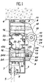
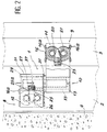
- Les Figures 1 et 2 sont respectivement des vues en coupe transversale et en élévation avec arrachement partiel d'une paumelle selon l'invention.
- La Figure 3 est une vue en perspective éclatée des principaux éléments constituant la paumelle des Figures 1 et 2.
- Comme représenté sur ces Figures, la paumelle considérée, désignée dans son ensemble sous la référence 1 est prévue pour réaliser l'articulation mutuelle d'un dormant 2 et d'un ouvrant 3 d'une porte ou analogue, constitué chacun au moyen d'un profilé métallique creux, d'un type en lui-même connu et dont le détail de la réalisation n'importe pas directement à l'invention. Le dormant 2 est immobilisé par tout moyen classique (non représenté)vis-à-vis d'un mur 4 ou d'une structure de support analogue, tandis que l'ouvrant 3 supporte dans l'exemple représenté un panneau vitré 5, monté dans le profilé correspondant avec interposition d'un joint 6 et d'une cale de positionnement 7.
- Conformément à une disposition également bien connue dans toute réalisation classique d'une paumelle de ce genre, celle-ci comporte deux corps complémentaires, respectivement 8 et 9, destinés à être fixés l'un sur l'ouvrant, l'autre sur le dormant, les deux corps étant articulés mutuellement et dans le prolongement l'un de l'autre autour d'une fiche ou axe d'articulation 10.
- Le corps 8 se compose d'un élément cylindrique 11 à l'intérieur duquel s'engage l'axe d'articulation 10, cet élément étant prolongé par une patte d'appui 12, apte à venir s'appliquer contre une face latérale du profilé métallique constituant le dormant 2, en immobilisant le corps contre cette face de la façon décrite plus loin. De la même manière, le corps 9 comporte un élément cylindrique 13 disposé dans le prolongement de l'élément 11 et recevant également l'axe 10, cet élément 13 comprenant de même une patte d'appui et d'immobilisation 14 contre le profilé de l'ouvrant 3.
- Les corps 8 et 9 sont de préférence identiques, notamment en ce qui concerne tes moyens mis en oeuvre pour assurer leur immobilisation vis-à-vis des profilés contre lesquels s'appliquent leurs pattes d'appui 12 et 14. Ainsi et dans le mode de réalisation représenté, chaque patte comporte, en regard du profilé correspondant, un logement borgne 15, taraudé intérieurement, ce logement étant ainsi invisible de l'extérieur de la paumelle lorsque cette dernière est fixée sur l'ouvrant et le dormant.
- Conformément à l'invention, l'immobilisation des deux corps 8 et 9 de la paumelle est réalisée en disposant à l'intérieur des profilés tubulaires du dormant et de l'ouvrant respectivement une pièce d'insert 16, apte à librement coulisser dans ta région interne 17 de ces profilés. Avantageusement, chaque pièce 16 comporte des extensions ou bords latéraux 16a, convenablement rabattus vers l'extérieur de manière à permettre le guidage de la pièce à l'intérieur du profilé, notamment le long de nervures 17a prévues dans la région 17 et formant glissières longitudinales.
- Chaque pièce 16 comporte deux alésages transversaux superposés respectivement 18 et 19, destiné chacun à recevoir un goujon 20 ou 21 comme le montre plus particulièrement la vue en perspective éclatée de la Figure 3. Chacun de ces goujons comporte un corps fileté 22 et une face inclinée 23 terminée par un prolongement 24 muni de préférence d'une rainure 24a, permettant de commander la rotation du goujon dans son alésage de réception de telle sorte que son corps fileté 22 vienne coopérer avec le trou taraudé 15 ménagé dans les pattes d'appui et d'immobilisation 12 et 14 des corps 8 et 9, en les solidarisant ainsi avec les goujons et par suite avec la pièce 16 qui les supporte.
- Les goujons 20 et 21 sont alors eux-mêmes bloqués dans leurs alésages de réception 18 et 19 grâce à une vis pointeau transversale 25, montée dans un trou de passage 25a prévu dans la face de chaque profilé dirigé vers le jeu ou battement 39 prévu entre l'ouvrant et le dormant, cette vis 25 comprenant une extrémité en pointe 26 et une partie médiane filetée 27, apte à se visser dans un passage taraudé 28 traversant la pièce 16, en communiquant avec les alésages 18 et 19 de cette dernière. Dans ces conditions, la vis 25 vient engager sa pointe 26 au contact des faces inclinées 23 des goujons 20 et 21, en réalisant leur blocage progressif et leur immobilisation vis-à-vis de la pièce 16.
- L'équipement de la paumelle se complète en constituant l'axe d'articulation 10 de telle sorte qu'il puisse tolérer un léger ajustement transversal de position des deux corps 8 et 9 lors du montage de ces derniers et de leur immobilisation contre l'ouvrant et le dormant. A cet effet, la paumelle comporte une chemise cylindrique 29, propre à s'engager dans le logement de même profil 30 prévu dans l'élément 11 de la pièce 8, cette chemise comprenant à l'une de ses extrémités une collerette d'arrêt 31. La chemise 29 présente un axe légèrement excentré vis-à-vis de celui du logement 30 et est prévu pour recevoir une tige cylindrique de liaison 32. L'élément cylindrique 13 de la pièce 8 coopère à son tour avec une seconde chemise 33, montée dans un logement 34 de l'élément cylindrique, cette seconde chemise présentant elle-même un logement 35 recevant l'extrémité de la tige 32 mais dont l'axe est exactement aligné avec celui du logement 34. La chemise 33 comporte extérieurement une nervure 36 apte à coopérer avec une rainure 37 prévue dans ce logement 34.
- Au montage, la seconde chemise 33 est immobilisée dans le logement 34 par sa nervure 36. L'axe de la tige de liaison 32 est dans ces conditions fixé en position. En revanche, du fait de son léger excentrement, une rotation sur elle-même de la chemise 29 dans son logement 30 se traduit par un décalage axial de la pièce 8, permettant un ajustement final convenable des deux parties de la pauamelle. Une fois cet alignement réalisé, la chemise 29 est bloquée en position par une vis sans tête 38 vissée dans un trou taraudé de l'élément cylindrique 11.
- On réalise ainsi une paumelle particulièrement bien adaptée à un montage sur des profilés creux d'une menuiserie métallique pour articuler ensemble un ouvrant et un dormant. L'organe de verrouillage en position des deux parties de la paumelle, constitué par une vis pointeau transversale est placé dans le battement de la porte ou analogue, c'est-à-dire dans une endroit inaccessible lorsque l'ouvrant est appliqué sur le dormant. La paumelle ne présente donc aucun point faible à l'extérieur de la structure tubulaire de la porte. En outre, l'absence de moyens de liaison extérieurs permet d'affiner son contour et de mieux l'intégrer dans un ensemble fonctionnel approprié.
Claims (5)
- Ensemble d'articulation pour une structure en profilés métalliques tubulaires, comportant une paumelle formée de deux corps complémentaires (8, 9), respectivement fixés sur un ouvrant (3) et sur un dormant (2) ou un autre ouvrant à articuler mutuellement l'un par rapport à l'autre, ces corps (8, 9) comportant chacun un élément cylindrique (11, 13) recevant un axe (10) d'articulation autour duquel pivote l'ouvrant vis-à-vis du dormant ou de l'autre ouvrant, chaque corps (8, 9) comprenant en outre une patte de fixation (12, 14) contre la surface de l'ouvrant ou du dormant correspondant, chaque patte de fixation (12, 14) étant appliquée contre la surface d'un profilé tubulaire de l'ouvrant ou du dormant et comportant au moins un logement borgne taraudé (15), ce dernier recevant le corps fileté (22) d'un goujon (20, 21) traversant un passage prévu dans cette surface et s'engageant dans un alésage de réception (18, 19) menagé dans une pièce d'insert (16), montée par coulissement à l'intérieur du profilé tubulaire, caractérisé en ce que chacune des pattes de fixation (12, 14) comporte deux logements borgnes taraudés (18, 19) superposés, recevant respectivement un goujon (20, 21), les deux goujons (20, 21) présentant chacun au moins une face inclinée (23), destinée à coopérer avec la pointe (26) d'une vis pointeau (25) s'étendant perpendiculairement à la direction de ces goujons (20, 21) dans leurs alésages de réception (18, 19), afin de bloquer ces goujons (20, 21) par rapport à la pièce d'insert (16) et à immobiliser le corps contre le profilé.
- Ensemble selon la revendication 1, caractérisé en ce que chaque profilé tubulaire de l'ouvrant ou du dormant comporte une région interne (17) de même section que la pièce d'insert, dont la face dirigée vers le jeu ou battement (39) entre l'ouvrant et le dormant comporte un trou (25a) pour le passage de la vis pointeau de blocage.
- Ensemble selon la revendication 2, caractérisé en ce que la pièce d'insert comporte des extensions longitudinales rabattues (16a) de manière à former une zone d'appui coopérant avec des glissières (17a) prévues dans le profilé recevant cette pièce.
- Ensemble selon l'une quelconque des revendications 1 à 3, caractérisé en ce que l'un des éléments cylindriques (13) d'un corps (9) reçoit une chemise interne (33) dans laquelle tourillonne l'axe d'articulation (10), l'élément cylindrique (11) de l'autre corps (8) comportant également une chemise mais disposée dans un logement (30) légèrement excentré de manière à permettre d'ajuster l'alignement des deux chemises et la verticalité du passage recevant une tige de liaison (32) entre les deux corps.
- Ensemble selon la revendication 4, caractérisé en ce qu'une au moins des chemises (29) est associée à une vis sans tête (38) montée dans un trou taraudé de l'élément cylindrique (11) recevant cette chemise et permettant son blocage en position autour de l'axe.
Applications Claiming Priority (2)
| Application Number | Priority Date | Filing Date | Title |
|---|---|---|---|
| FR9011226 | 1990-09-11 | ||
| FR9011226A FR2666617B1 (fr) | 1990-09-11 | 1990-09-11 | Paumelle perfectionnee, notamment pour structure en profiles metalliques tubulaires. |
Publications (2)
| Publication Number | Publication Date |
|---|---|
| EP0475823A1 EP0475823A1 (fr) | 1992-03-18 |
| EP0475823B1 true EP0475823B1 (fr) | 1995-08-09 |
Family
ID=9400232
Family Applications (1)
| Application Number | Title | Priority Date | Filing Date |
|---|---|---|---|
| EP91402371A Expired - Lifetime EP0475823B1 (fr) | 1990-09-11 | 1991-09-04 | Paumelle perfectionnée, notamment pour structure en profiles métalliques tubulaires |
Country Status (8)
| Country | Link |
|---|---|
| EP (1) | EP0475823B1 (fr) |
| AT (1) | ATE126314T1 (fr) |
| DE (1) | DE69111947T2 (fr) |
| ES (1) | ES2077196T3 (fr) |
| FR (1) | FR2666617B1 (fr) |
| GR (1) | GR3017290T3 (fr) |
| HK (1) | HK74196A (fr) |
| PT (1) | PT98910B (fr) |
Cited By (1)
| Publication number | Priority date | Publication date | Assignee | Title |
|---|---|---|---|---|
| DE20107606U1 (de) * | 2001-05-04 | 2002-09-12 | Dr. Hahn GmbH & Co. KG, 41189 Mönchengladbach | Einrichtung zur Befestigung eines Beschlagteils |
Families Citing this family (4)
| Publication number | Priority date | Publication date | Assignee | Title |
|---|---|---|---|---|
| DE29602085U1 (de) | 1996-02-07 | 1997-06-05 | Dr. Hahn GmbH & Co. KG., 41189 Mönchengladbach | Bandanordnung für Türen, Fenster u.dgl. |
| DE29617826U1 (de) * | 1996-10-14 | 1998-02-12 | Dr. Hahn GmbH & Co. KG., 41189 Mönchengladbach | Bandanordnung für Fenster, Türen u.dgl. |
| AT408781B (de) * | 1999-10-14 | 2002-03-25 | Friedrich Jun Luxner | Rohr mit drehbaren eisenringen |
| GB2590056A (en) * | 2019-10-11 | 2021-06-23 | Era Home Security Ltd | Hinge |
Family Cites Families (4)
| Publication number | Priority date | Publication date | Assignee | Title |
|---|---|---|---|---|
| DE1559983A1 (de) * | 1964-06-25 | 1969-12-18 | Schuermann & Co Heinz | Band,insbesondere fuer Metalltueren od.dgl. |
| CH596422A5 (en) * | 1975-07-08 | 1978-03-15 | Alusuisse | Door hinge with tolerance adjustment |
| FR2397508A1 (fr) * | 1977-07-12 | 1979-02-09 | Gautier Ets P | Dispositif pour l'articulation de deux elements notamment d'une porte sur un meuble |
| CH648378A5 (de) * | 1980-07-30 | 1985-03-15 | Walter Pfaeffli | Tuerband zur befestigung eines tuerfluegels an einer tuerzarge. |
-
1990
- 1990-09-11 FR FR9011226A patent/FR2666617B1/fr not_active Expired - Fee Related
-
1991
- 1991-09-04 EP EP91402371A patent/EP0475823B1/fr not_active Expired - Lifetime
- 1991-09-04 ES ES91402371T patent/ES2077196T3/es not_active Expired - Lifetime
- 1991-09-04 AT AT91402371T patent/ATE126314T1/de not_active IP Right Cessation
- 1991-09-04 DE DE69111947T patent/DE69111947T2/de not_active Expired - Fee Related
- 1991-09-09 PT PT98910A patent/PT98910B/pt not_active IP Right Cessation
-
1995
- 1995-09-01 GR GR950402413T patent/GR3017290T3/el unknown
-
1996
- 1996-04-25 HK HK74196A patent/HK74196A/xx not_active IP Right Cessation
Cited By (1)
| Publication number | Priority date | Publication date | Assignee | Title |
|---|---|---|---|---|
| DE20107606U1 (de) * | 2001-05-04 | 2002-09-12 | Dr. Hahn GmbH & Co. KG, 41189 Mönchengladbach | Einrichtung zur Befestigung eines Beschlagteils |
Also Published As
| Publication number | Publication date |
|---|---|
| ATE126314T1 (de) | 1995-08-15 |
| ES2077196T3 (es) | 1995-11-16 |
| DE69111947T2 (de) | 1996-03-21 |
| FR2666617A1 (fr) | 1992-03-13 |
| PT98910B (pt) | 1999-01-29 |
| FR2666617B1 (fr) | 1993-07-23 |
| GR3017290T3 (en) | 1995-12-31 |
| DE69111947D1 (de) | 1995-09-14 |
| HK74196A (en) | 1996-05-03 |
| EP0475823A1 (fr) | 1992-03-18 |
| PT98910A (pt) | 1993-10-29 |
Similar Documents
| Publication | Publication Date | Title |
|---|---|---|
| EP1026349B1 (fr) | Poignée d'ouvrant de véhicule automobile | |
| EP0430756A1 (fr) | Charnière élastique | |
| EP0281442A1 (fr) | Dispositif de réglage de la position angulaire d'un volant sur une colonne de direction de véhicule automobile et volant équipé d'un tel dispositif | |
| FR2722527A1 (fr) | Dispositif de verrouillage pour chassis a frappe | |
| FR2719269A1 (fr) | Ensemble pour la fixation ajustable selon trois dimensions d'un dispositif d'éclairage et/ou de signalisation de véhicule automobile. | |
| EP0475823A1 (fr) | Paumelle perfectionnée, notamment pour structure en profiles métalliques tubulaires | |
| FR2688255A1 (fr) | Support a alignement automatique pour poignee de porte, fenetre et analogues. | |
| EP1059409B1 (fr) | Dispositif de renvoi de fouillot | |
| EP0651122B1 (fr) | Perfectionnement aux paumelles d'articulation d'un ouvrant sur un dormant | |
| FR2658236A1 (fr) | Ensemble pour la realisation d'un chassis de survitrage. | |
| FR2747761A1 (fr) | Dispositif d'assemblage en equerre et de bridage entre deux profiles metalliques creux, disposes selon deux directions perpendiculaires | |
| FR2647319A1 (fr) | Perfectionnements apportes aux boitiers, en particulier pour le maquillage | |
| FR2734013A1 (fr) | Dispositif de verrouillage d'un ouvrant de vehicule automobile comportant des moyens perfectionnes de montage d'un capuchon d'habillage | |
| FR2549518A1 (fr) | Penture reglable, notamment pour la fixation d'un volet sur des gonds preexistants | |
| FR2759333A1 (fr) | Mecanisme d'articulation pour siege de vehicule, et siege de vehicule comportant un tel mecanisme | |
| FR2562196A1 (fr) | Joint d'etancheite du type profile, en particulier pour l'etancheite de portes coulissantes de vehicules | |
| FR2921683A1 (fr) | Dispositif de montage d'une patte d'articulation pour vantail sur un gond. | |
| EP0453336B1 (fr) | Dispositif pour le réglage et la fixation d'un organe sur un support | |
| EP0233813A1 (fr) | Dispositif de réglage perfectionné de la position angulaire d'un organe sur un arbre, notamment d'un volant sur un arbre de direction | |
| FR2611797A1 (fr) | Charniere, notamment pour armoire electrique, et armoire, en particulier armoire electrique, comportant une telle charniere | |
| EP1026356B1 (fr) | Panneau formé d'une plaque en verre, muni d'au moins un dispositif d'assemblage à une structure voisine | |
| FR2497864A1 (fr) | Ensemble reglable de ferrure d'angle situe du cote du battant d'une fenetre tournante et basculante | |
| BE1008701A4 (fr) | Piece de fixation d'une ferrure dans un profile d'ouvrant de fenetre. | |
| FR2751605A1 (fr) | Dispositif de fixation d'un moyeu de volant de direction de vehicule, sur une extremite d'un arbre de direction | |
| FR2835276A1 (fr) | Cartouche de charniere pour une charniere de porte, notamment pour une charniere de portiere de vehicule, charniere equipee de ladite cartouche de charniere et procede de montage d'une telle cartouche dans une charniere |
Legal Events
| Date | Code | Title | Description |
|---|---|---|---|
| PUAI | Public reference made under article 153(3) epc to a published international application that has entered the european phase |
Free format text: ORIGINAL CODE: 0009012 |
|
| AK | Designated contracting states |
Kind code of ref document: A1 Designated state(s): AT BE CH DE DK ES GB GR IT LI LU NL SE |
|
| 17P | Request for examination filed |
Effective date: 19920328 |
|
| RAP1 | Party data changed (applicant data changed or rights of an application transferred) |
Owner name: ALCAN FRANCE |
|
| 17Q | First examination report despatched |
Effective date: 19930826 |
|
| GRAA | (expected) grant |
Free format text: ORIGINAL CODE: 0009210 |
|
| AK | Designated contracting states |
Kind code of ref document: B1 Designated state(s): AT BE CH DE DK ES GB GR IT LI LU NL SE |
|
| PG25 | Lapsed in a contracting state [announced via postgrant information from national office to epo] |
Ref country code: DK Effective date: 19950809 Ref country code: AT Effective date: 19950809 |
|
| REF | Corresponds to: |
Ref document number: 126314 Country of ref document: AT Date of ref document: 19950815 Kind code of ref document: T |
|
| GBT | Gb: translation of ep patent filed (gb section 77(6)(a)/1977) |
Effective date: 19950812 |
|
| REF | Corresponds to: |
Ref document number: 69111947 Country of ref document: DE Date of ref document: 19950914 |
|
| ITF | It: translation for a ep patent filed | ||
| PG25 | Lapsed in a contracting state [announced via postgrant information from national office to epo] |
Ref country code: SE Effective date: 19951109 |
|
| REG | Reference to a national code |
Ref country code: ES Ref legal event code: FG2A Ref document number: 2077196 Country of ref document: ES Kind code of ref document: T3 |
|
| REG | Reference to a national code |
Ref country code: GR Ref legal event code: FG4A Free format text: 3017290 |
|
| PLBE | No opposition filed within time limit |
Free format text: ORIGINAL CODE: 0009261 |
|
| STAA | Information on the status of an ep patent application or granted ep patent |
Free format text: STATUS: NO OPPOSITION FILED WITHIN TIME LIMIT |
|
| PGFP | Annual fee paid to national office [announced via postgrant information from national office to epo] |
Ref country code: GR Payment date: 19960724 Year of fee payment: 6 |
|
| 26N | No opposition filed | ||
| PGFP | Annual fee paid to national office [announced via postgrant information from national office to epo] |
Ref country code: LU Payment date: 19960801 Year of fee payment: 6 |
|
| PGFP | Annual fee paid to national office [announced via postgrant information from national office to epo] |
Ref country code: BE Payment date: 19960805 Year of fee payment: 6 |
|
| PGFP | Annual fee paid to national office [announced via postgrant information from national office to epo] |
Ref country code: GB Payment date: 19960809 Year of fee payment: 6 |
|
| REG | Reference to a national code |
Ref country code: CH Ref legal event code: NV Representative=s name: BOVARD AG PATENTANWAELTE |
|
| PGFP | Annual fee paid to national office [announced via postgrant information from national office to epo] |
Ref country code: ES Payment date: 19960911 Year of fee payment: 6 Ref country code: CH Payment date: 19960911 Year of fee payment: 6 |
|
| PGFP | Annual fee paid to national office [announced via postgrant information from national office to epo] |
Ref country code: NL Payment date: 19960930 Year of fee payment: 6 |
|
| PGFP | Annual fee paid to national office [announced via postgrant information from national office to epo] |
Ref country code: DE Payment date: 19961127 Year of fee payment: 6 |
|
| PG25 | Lapsed in a contracting state [announced via postgrant information from national office to epo] |
Ref country code: LU Free format text: LAPSE BECAUSE OF NON-PAYMENT OF DUE FEES Effective date: 19970904 Ref country code: GB Free format text: LAPSE BECAUSE OF NON-PAYMENT OF DUE FEES Effective date: 19970904 |
|
| PG25 | Lapsed in a contracting state [announced via postgrant information from national office to epo] |
Ref country code: ES Free format text: LAPSE BECAUSE OF THE APPLICANT RENOUNCES Effective date: 19970905 |
|
| PG25 | Lapsed in a contracting state [announced via postgrant information from national office to epo] |
Ref country code: LI Free format text: LAPSE BECAUSE OF NON-PAYMENT OF DUE FEES Effective date: 19970930 Ref country code: GR Free format text: LAPSE BECAUSE OF NON-PAYMENT OF DUE FEES Effective date: 19970930 Ref country code: CH Free format text: LAPSE BECAUSE OF NON-PAYMENT OF DUE FEES Effective date: 19970930 Ref country code: BE Free format text: LAPSE BECAUSE OF NON-PAYMENT OF DUE FEES Effective date: 19970930 |
|
| BERE | Be: lapsed |
Owner name: ALCAN FRANCE Effective date: 19970930 |
|
| PG25 | Lapsed in a contracting state [announced via postgrant information from national office to epo] |
Ref country code: NL Free format text: LAPSE BECAUSE OF NON-PAYMENT OF DUE FEES Effective date: 19980401 |
|
| GBPC | Gb: european patent ceased through non-payment of renewal fee |
Effective date: 19970904 |
|
| REG | Reference to a national code |
Ref country code: CH Ref legal event code: PL |
|
| NLV4 | Nl: lapsed or anulled due to non-payment of the annual fee |
Effective date: 19980401 |
|
| PG25 | Lapsed in a contracting state [announced via postgrant information from national office to epo] |
Ref country code: DE Free format text: LAPSE BECAUSE OF NON-PAYMENT OF DUE FEES Effective date: 19980603 |
|
| REG | Reference to a national code |
Ref country code: ES Ref legal event code: FD2A Effective date: 20001009 |
|
| PG25 | Lapsed in a contracting state [announced via postgrant information from national office to epo] |
Ref country code: IT Free format text: LAPSE BECAUSE OF NON-PAYMENT OF DUE FEES Effective date: 20050904 |