EP0474344B1 - Kinofilm-zu-Video-Umwandlung - Google Patents
Kinofilm-zu-Video-Umwandlung Download PDFInfo
- Publication number
- EP0474344B1 EP0474344B1 EP91306368A EP91306368A EP0474344B1 EP 0474344 B1 EP0474344 B1 EP 0474344B1 EP 91306368 A EP91306368 A EP 91306368A EP 91306368 A EP91306368 A EP 91306368A EP 0474344 B1 EP0474344 B1 EP 0474344B1
- Authority
- EP
- European Patent Office
- Prior art keywords
- film
- video signal
- image
- frame
- correction
- Prior art date
- Legal status (The legal status is an assumption and is not a legal conclusion. Google has not performed a legal analysis and makes no representation as to the accuracy of the status listed.)
- Expired - Lifetime
Links
- 238000006243 chemical reaction Methods 0.000 title claims description 15
- 238000012937 correction Methods 0.000 claims description 38
- 238000000034 method Methods 0.000 claims description 17
- 230000000694 effects Effects 0.000 claims description 15
- 238000012545 processing Methods 0.000 claims description 10
- 238000006073 displacement reaction Methods 0.000 claims description 8
- 238000009795 derivation Methods 0.000 claims 3
- 238000001514 detection method Methods 0.000 description 22
- 238000003708 edge detection Methods 0.000 description 21
- 238000009432 framing Methods 0.000 description 4
- 238000010276 construction Methods 0.000 description 2
- 230000009977 dual effect Effects 0.000 description 2
- 238000012986 modification Methods 0.000 description 2
- 230000004048 modification Effects 0.000 description 2
- 230000002708 enhancing effect Effects 0.000 description 1
- 230000002093 peripheral effect Effects 0.000 description 1
- 238000013519 translation Methods 0.000 description 1
Images

Classifications
-
- H—ELECTRICITY
- H04—ELECTRIC COMMUNICATION TECHNIQUE
- H04N—PICTORIAL COMMUNICATION, e.g. TELEVISION
- H04N5/00—Details of television systems
- H04N5/222—Studio circuitry; Studio devices; Studio equipment
- H04N5/253—Picture signal generating by scanning motion picture films or slide opaques, e.g. for telecine
Definitions
- This invention relates to methods of and apparatus for photographic movie film to electronic video signal conversion.
- each frame of the film When a photographic movie film is converted to a video signal in a telecine, each frame of the film must be mechanically positioned so as to be aligned in the same position as the previous frames, to enable an accurately framed video signal to be derived. Hitherto, this has been done by pin registration, wherein an interference fit, slightly tapered pin is fitted into the film sprocket holes. Due to mechanical inaccuracies, this pin registration method does not give perfect results, and in consequence there may be an irritating lack of steadiness (so-called weave) in the image reproduced from the video signal. There are, moreover, other problems with this pin registration method. In particular, due to mechanical limitations, the conversion cannot be performed in real time, and typically the transport speed is as low as two frames per second. Also, there is a risk of damage to the sprocket holes by the tightly fitting pin. There is also the associated problem that movie cameras are noisy in operation due to the operation of the mechanism which meshes with the film sprocket holes to advance the film.
- GB-A-2 212 024 discloses a method of (and apparatus for) photographic movie film to electronic video signal conversion, the method comprising the steps of:
- Said registration marks or registration features may be L-shaped registration marks exposed on said film respectively adjacent to two diagonally opposite corners of each frame thereof, and the positions of said registration marks may be read by a charge coupled device sensor.
- the first embodiment to be described is for the conversion of 35mm photographic movie film 1 to a high definition video signal, but it will be understood that the invention can be applied to the conversion of other sized movie films to other video signals.
- the film 1 is passed through a modified form of telecine 11 to derive a video signal.
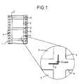
- the film 1 has thereon registration marks 2 associated with each frame 3, and the telecine 11 is modified to derive error signals from which are derived a control signal which is supplied together with the derived video signal to a digital picture manipulator 12 which operates to enhance the framing of the video signal, and so correct for any inaccuracy in the framing of the film 1 in the telecine 11.
- the apparatus thus avoids the problems mentioned above in connection with the pin registration method of framing, and in particular permits relatively high speed operation, if necessary up to or even beyond real time operation.
- the film 1 has sprocket holes 4, and the registration marks 2 are preferably in the form of two similar L-shaped marks associated respectively with diagonally opposite corners of each frame 3, and positioned as shown in the space between the frame 3 and the adjacent sprocket holes 4. As indicated in the enlarged portion of the figure, the width of each limb of each registration mark 2 may be 0.4mm.
- the respective registration marks 2 are very accurately aligned in position and orientation relative to each frame 3, and to achieve this they are preferably exposed on the film 1 in the camera, as the film 1 is shot. Alternatively, they may be exposed on the film 1 subsequently, but still prior to processing of the film 1, for example by reference to the positions of the sprocket holes 4, or they may be printed on the film 1 subsequent to processing, again by reference to the positions of the sprocket holes 4. These latter two alternatives are not preferred, due to the greater difficulty of obtaining accurate alignment of the registration marks 2 relative to the frames 3, but nonetheless they do have utility, in particular in the case of pre-existing films 1 where the decision to provide registration marks 2 has not been made until subsequent to shooting.
- the registration marks 2 contrast with the transparency or opacity of the areas of the film 1 where they are provided, so as to be optically readable.
- the registration marks can be black, and vice versa.
- the first embodiment comprises the telecine 11 which incorporates means, not shown, to hold the film 1 and advance it substantially exactly frame by frame by engagement with the sprocket holes 4.
- No mechanism as used in the pin registration method referred to above, is provided.
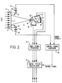
- parallel light from a source (not shown) is caused to fall on the frame 3, so that images thereof are formed on three charge coupled device sensors 13 of the telecine 11 by a lens system 14 and dichroic mirrors 15, in known manner.
- From the charge coupled device sensors 13 are derived red (R), green (G) and blue (B) video signals, again in known manner, which are supplied to a video signal processor 16 for any necessary processing.
- the light falling on the film 1 falls on two angled mirrors 17 located to correspond in position with the two registration marks 2 respectively associated with the frame 3 currently being imaged.
- the reflected light passes through respective objective lenses 18, which may be x50 magnification lenses, and falls on respective charge coupled device sensors 19 which derive respective error signals representative of the divergence of the respective registration marks 2 from the positions they would occupy if the frame 2 currently being imaged were precisely located at the required aligned position.
- control signal generator 20 which derives therefrom a single control signal (or if required by the subsequent circuitry, a group of control signals) representative of the translational movement in the horizontal and in the vertical direction of the image represented by the video signals derived by the telecine 11, and of the rotational movement of said image, which are together required to bring said image to the exact position which it would occupy if the film 1 were positioned such that the frame currently being imaged were in the precisely required position.
- the charge coupled device sensors 19 may, for example, sense the positions of the outer edges of the two limbs of each registration mark 2.
- This control signal and the three video signals from the video signal processor 16 are supplied to the digital picture manipulator 12.
- the three video signals may be derived in digital form by the telecine 11, or they may be derived in analogue form and be converted to digital form by the video signal processor 16.
- the digital picture manipulator 12 is conveniently in the form of a digital video effects apparatus of known form, the essential requirements being that it can manipulate the video signals so as to have the effect of translationally moving the corresponding image in the horizontal and the vertical directions, preferably with sub-pixel accuracy, and of rotating the corresponding image, so enhancing the frame alignment of the video signals, which are then supplied for further processing as required, such further processing not being of relevance to the present invention.
- the effect is therefore to correct for any minor inaccuracy in the positioning of the film 1 relative to the position it should occupy for each frame 3 thereof to be aligned in precisely the same position when it is being imaged. In this way 'weave' in the reproduced image can be eliminated.
- the apparatus can be operated at relatively high speed, as no mechanical means is required to achieve the exact positioning of each frame 3 of the film 1.
- the second embodiment to be described is likewise for the conversion of 35mm photographic movie film 1 to a high definition video signal.
- the film 1 is continuously advanced from a feed reel 32 to a take-up reel 33 by a film advancing mechanism.
- a light beam L projected from a light source 35 is adjusted by an aperture 36 and is then projected on the film 1.
- a transmitted light beam L1 which has passed through the film 1 is incident on an image pick-up device 39 through a projection lens 37 and a beam splitter 38.
- the light beam L1 is converted to a video signal VD in the image pick-up device 39, and the video signal VD is supplied to a special effects device 40 such as a digital picture manipulator.
- the video signal VD is subjected to interpolation processing to correct the framing and is then supplied as an output video signal VD OUT .
- the beam splitter 38 deflects a vertically polarized component of the light beam L1 as a polarized light beam L2 to an edge sensor 42 through a concave lens 41 to form an erect image of the light beam L1 on the edge sensor 42.
- the concave lens 41 enhances the misregistration detection accuracy of the edge sensor 42 by diverging the incident polarized light beam L2.
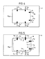
- the polarized light beam L2 is projected to a reference position on the surface of the edge sensor 42, so that the projected picture which corresponds to the film picture of the film 1 is formed by the polarized light beam L2 within a reference picture frame W REF .
- line sensors U1, U2; D1, D2 and S1, S2 provide edge detection signals S U1 , S U2 ; S D1 , S D2 and S S1 , S S2 , which are light reception outputs corresponding to projected positions of edges of the reference picture frame W REF , to an upper edge detection circuit 43U, a lower edge detection circuit 43D and a lateral edge detection circuit 43S, respectively.
- the line sensors U1, U2; D1, D2, and S1, S2 are arranged at three edges of the reference picture frame W REF ; an upper edge E U , a lower edge E D and a lateral edge E S , and extend perpendicularly therefrom.
- the upper edge detection circuit 43U, the lower edge detection circuit 43D and the lateral edge detection circuit 43S detect projected positions of the projected picture on the upper edge E U1 , the lower edge E D1 and the lateral edge E S1 according to output levels of the edge detection signals S U1 , S U2 ; S D1 , S D2 and S S1 , S S2 which are supplied from the line sensors U1, U2; D1, D2 and S1, S2.
- the projected positions detected are supplied as edge position detection signal S U , S D and S S to a misregistration amount detection/correction circuit 44.
- the misregistration amount detection/correction circuit 44 performs operations on amounts of both vertical and lateral misregistration of the projected picture relative to the reference picture frame W REF , and the angle of rotation of the picture frame W about the lower left corner of the reference picture frame W REF on the basis of the edge position detection signals S U , S D and S S supplied from the upper edge detection circuit 43U, the lower edge detection circuit 43D and the lateral edge detection circuit 43S. Then, a correction signal S H which corresponds to each misregistration amount is supplied to the special effects device 40.
- the special effects device 40 stores the video signal VD in a frame memory, and the position of the picture frame W of the projected picture which is represented by the video signal VD is corrected to remove the misregistration in dependence on the correction signal S H .
- the projected picture which corresponds to the film picture is projected on the edge sensor 42 such that the projected picture is shifted to a position, indicated by the dot-and-dash line, by both parallel translation to the upper right side and counter-clockwise rotation from the position of the reference picture frame W REF .
- the line sensors U1 and U2 supply edge detection signals S U1 and S U2 , according to the position of an upper edge E U1 , to the upper edge detection circuit 13U.
- the upper edge detection circuit 43U determines the position where the upper edge E U1 intersects the line sensor U1, and the upper edge detection circuit 43U supplies the determined position as an edge position detection signal S U to the misregistration amount detection/correction circuit 44. Moreover, the upper edge detection circuit 43U determines from a light reception output signal S U2 a position where the upper edge E U2 intersects the line sensor U2, and the upper edge detection circuit 43U supplies the position as an edge position detection signal S U to the misregistration amount detection/correction circuit 44.
- the lower edge detection circuit 43D and the lateral edge detection circuit 43S determine positions where the lower edge E D1 and the lateral edge E S1 cross the line sensors D1, D2 and S1, S2 on the basis of edge detection signals S D1 , S D2 and S S1 , S S2 , respectively. These positions are supplied as edge position detection signals S D and S S to the misregistration amount detection/correction circuit 44.
- the misregistration amount detection/correction circuit 44 performs operations on vertical and lateral parallel displacements of the picture frame W of the projected picture in relation to the reference picture frame W REF and the amount of rotation of the picture frame W about the lower left corner of the reference picture frame W REF on the basis of these position detection signals S U , S D and S S . Then, the calculated amounts are supplied as correction signals S H to the special effects device 40.
- the special effects device 40 compensates picture data according to the correction signals S H , so that the vertical and lateral parallel displacements and the rotation are cancelled thereby to return the picture frame W of the projected picture to the position to coincide with the reference picture frame W REF .
- the picture data are the video signal VD stored as digital data in the frame memory.
- the special effects device 40 corrects the projected picture by correction signals S H to position the projected picture within the reference picture frame W REF thereby to output it as an output video signal V DOUT with exact frame positioning.
- the misregistration amount detection/correction circuit 44 then provides correction signals S H according to an amount of misregistration of the lower edge E D1 which is detected by the line sensors D1 and D2.
- the window frame When an image, such as of a window frame, not of the same inclination as the lateral edge, appears in a film picture to be projected, the window frame might be erroneously detected as a lateral edge E S by the lateral edge sensors S1 and S2. To avoid false detection in such a case, if the difference between the inclination of the lateral edge E S , which is calculated from the inclination of the upper edge E U , and the inclination of the lateral edge E S as actually detected is larger than a predetermined amount, the misregistration amount detection/correction circuit 44 controls the correction signals S H to supply the video signal VD without correcting it.
- a shift of a projected picture can be detected as misregistration of the picture frame W of the projected picture from the reference picture frame W REF .
- the video signal VD is corrected and thus, a film image pick-up system having enhanced frame alignment is obtained.
- misregistration of the projected picture is detected by the edge sensor 42 including six line sensors.
- the embodiment may use a charge coupled device 45, as shown in Figure 6, to detect a projected position of a projected picture.
- the misregistration of the projected picture relative to a predetermined position may be calculated as the misregistration between the picture frame W of the projected picture and the reference picture frame W REF which has been previously stored.
- the misregistration amount detection/correction circuit 44 judges that the detected positional information relates to the picture frame W only when charge coupled elements which detect an edge are arranged along a straight line. According to the positional information, the misregistration is corrected.
- the charge coupled device 45 makes it possible to perform finer detection than is generally possible with six line sensors.
- the misregistration of the projected picture is detected with six line sensors.
- dual or two-piece photosensors may be used in such a manner that the division lines thereof are positioned along the edges of the reference picture frame W REF , and misregistration may then be detected on the basis of analogue outputs which are supplied from the dual photosensors.
- the light beam L1 which has passed through the film 1 is converted to the video signal VD by the image pick-up device 39, and the video signal VD is corrected on the basis of misregistration of the projected picture detected by the edge sensor 42.
- An image pick-up device including a charge coupled device with a misregistration judging area at an outer peripheral area of the reference picture frame W REF may be used instead.
- the image pick-up device 39 may detect misregistration of the picture frame W from the reference picture frame W REF as well as convert the projected pictures of the film 1.
- misregistration is directly determined on the image pick-up device 39, and hence detection and correction of misregistration can be carried out with high accuracy.
- the projected light beam L1 is split by the beam splitter 38, but some other device such as a half-silvered mirror can be used.
- two line sensors are arranged in the edge sensor 42 to correspond to each of the upper edge E U , the lower edge E D and the lateral edge E S , but different numbers of line sensors can be used.
- misregistration of a frame produced in converting a movie film to a video signal can be detected and corrected.
- registration features may, for example, be the corners of the frames 3 or of the sprocket holes 4, and the detection of these registration features, like the detection of the edges of the frame described in the second embodiment, is of particular advantage in the case of pre-existing films 1 which do not have the registration marks 2.
- the camera may be modified to produce the registration marks 2 on the film 1 in the required positions relative to each frame 3 at the time that the film 1 is exposed in the camera, so as to be transferred to a subsequent copy of the film 1 which is to be used for conversion to a video signal.
- the film sprocket holes 4 are no longer essential.
- a form of movie camera can be used which operates with plain film having no sprocket holes, and which has a mechanism, not relying on sprocket holes, to advance the film by a substantially constant distance for the exposure of each frame 3.
- Such a movie camera can be made quieter in operation than a movie camera of known form, wherein the film advance mechanism makes use of sprocket holes in the film 1.
Landscapes
- Engineering & Computer Science (AREA)
- Multimedia (AREA)
- Signal Processing (AREA)
- Studio Devices (AREA)
Claims (12)
- Verfahren zur Umwandlung eines fotografischen Kinofilms in ein elektronisches Videosignal, wobei das Verfahren die folgenden Schritte aufweist:rahmenweises Ausrichten des fotografischen Kinofilms (1) in einem Kinofilm-Videosignal-Umwandlungsgerät (11; 35 bis 39), um ein Videosignal herzuleiten; undVerarbeiten des Videosignals durch Bezugnahme auf Erfassungsmerkmale des Films (1), um die Rahmenausrichtung des Videosignals zu erhöhen, wobei ein Korrektursignal, das für den horizontalen und vertikalen Versatz eines Bildes repräsentativ ist, das durch das Videosignal in bezug auf eine Referenzposition des Bildes dargestellt wird, durch Bestimmen der Positionierung der Erfassungsmerkmale bestimmt wird (17 bis 20; 38 bis 44; 38 bis 41 und 43 bis 45), und das Videosignal in einem Korrekturgerät (12; 40) verarbeitet wird, um die horizontale und vertikale Position des Bildes in Abhängigkeit vom Korrektursignal zu korrigieren;dadurch gekennzeichnet, daßdas Korrektursignal ebenfalls für den Drehversatz des Bildes in Bezug auf die Referenzposition repräsentativ ist; unddas Korrekturgerät (12; 40), in welchem das Videosignal verarbeitet wird, ein digitales Videoeffektgerät ist, welches die Horizontal-, Vertikal- und Dreh-Position des Bildes in Abhängigkeit vom Korrektursignal korrigiert.
- Verfahren nach Anspruch 1, wobei die Erfassungsmerkmale die Ränder von Perforationslöchern (4) des Films (1) sind.
- Verfahren nach Anspruch 1, wobei die Erfassungsmerkmale die Ränder von Rahmen (3) des Films (1) sind.
- Verfahren nach Anspruch 1, das den Schritt zur Bildung der Erfassungsmerkmale auf dem fotografischen Kinofilm (1) in der Nähe der jeweiligen Rahmen (3) des Films umfaßt.
- Verfahren nach Anspruch 4, wobei die Erfassungsmerkmale L-förmige Markierungen (2) sind, die durch Belichtung des Films (1) gebildet werden.
- Verfahren nach Anspruch 5, wobei zwei Markierungen (2) mit jedem einzelnen Rahmen (3) des Films verknüpft sind und in der Nähe von diagonal gegenüberliegenden Ecken des jeweiligen Rahmens positioniert sind.
- Verfahren nach einem der vorherigen Ansprüche, wobei das digitale Videoeffektgerät (12; 40) die translatorische Verschiebung des Bildes, die durch das Videosignal in sowohl der horizontalen als auch in der vertikalen Richtung verkörpert wird, sub-pixelmäßig verarbeiten kann.
- Gerät zur Umwandlung eines fotografischen Kinofilms in ein elektronisches Videosignal, wobei das Gerät aufweist:ein Kinofilm-Videosignal-Umwandlungsgerät (11; 35 bis 39), in welchem der fotografische Kinofilm (1) rahmenweise ausgerichtet wird, um ein Videosignal herzuleiten; undeine Verarbeitungseinrichtung zur Verarbeitung des Videosignals unter Bezugnahme auf Erfassungsmerkmale des Films, um die Rahmenausrichtung des Videosignals zu erhöhen, wobei die Verarbeitungseinrichtung eine Korrektursignalherleitungseinrichtung (17 bis 20; 38 bis 44; 38 bis 41 und 43 bis 45) aufweist, um durch Bestimmen der Positionierung der Erfassungsmerkmale ein Korrektursignal herzuleiten, das für den horizontalen und vertikalen Versatz eines Bildes repräsentativ ist, das durch das Videosignal in Bezug auf eine Referenzposition des Bildes verkörpert wird, und ein Korrekturgerät (12; 40), um die horizontale und vertikale Position des Bildes in Abhängigkeit des Korrektursignals zu korrigieren;dadurch gekennzeichnet, daßdie Korrektursignalherleitungseinrichtung (17 bis 20; 38 bis 44; 38 bis 41 und 43 bis 45) ein Korrektursignal herleiten kann, das ebenfalls für den Drehversatz des Bildes in Bezug auf die Referenzposition repräsentativ ist; unddas Korrekturgerät (12; 40) ein digitales Videoeffektgerät ist, das die Horizontal-, Vertikal- und Dreh-Position des Bildes in Abhängigkeit vom Korrektursignal korrigieren kann.
- Gerät nach Anspruch 8, wobei die Erfassungsmerkmale Markierungen (2) sind, die durch Belichtung des Films (1) gebildet sind, Ränder von Perforationslöchern (4) des Films (1) oder Ränder von Rahmen (3) des Films (1).
- Gerät nach Anspruch 8 oder 9, wobei das digitale Videoeffektgerät (12,; 40) die translatorische Verschiebung des Bildes, die durch das Videosignal in sowohl der horizontalen Richtung als auch der vertikalen Richtung verkörpert wird, sub-pixelmäßig verarbeiten kann.
- Gerät nach einem der Ansprüche 8 bis 10, wobei die Korrektursignalherleitungseinrichtung (38 bis 41 und 43 bis 45) eine ladungsgekoppelte Einrichtung (45) aufweist, sowie eine Einrichtung (38 bis 41), um ein Bild der Erfassungsmerkmale auf der ladungsgekoppelten Einrichtung (45) zu bilden.
- Gerät nach einem der Ansprüche 8 bis 11, wobei das Kinofilm-Videosignal-Umwandlungsgerät (11; 35 bis 39) eine Filmübertragungsanlage (11) ist.
Applications Claiming Priority (2)
| Application Number | Priority Date | Filing Date | Title |
|---|---|---|---|
| GB9019004 | 1990-08-31 | ||
| GB9019004A GB2247586B (en) | 1990-08-31 | 1990-08-31 | Movie film to video conversion |
Publications (3)
| Publication Number | Publication Date |
|---|---|
| EP0474344A2 EP0474344A2 (de) | 1992-03-11 |
| EP0474344A3 EP0474344A3 (en) | 1992-07-01 |
| EP0474344B1 true EP0474344B1 (de) | 1996-03-20 |
Family
ID=10681431
Family Applications (1)
| Application Number | Title | Priority Date | Filing Date |
|---|---|---|---|
| EP91306368A Expired - Lifetime EP0474344B1 (de) | 1990-08-31 | 1991-07-15 | Kinofilm-zu-Video-Umwandlung |
Country Status (5)
| Country | Link |
|---|---|
| US (1) | US5194958A (de) |
| EP (1) | EP0474344B1 (de) |
| JP (1) | JPH04234270A (de) |
| DE (1) | DE69118059T2 (de) |
| GB (1) | GB2247586B (de) |
Cited By (2)
| Publication number | Priority date | Publication date | Assignee | Title |
|---|---|---|---|---|
| DE19636142C2 (de) * | 1996-09-06 | 2001-07-05 | Philips Corp Intellectual Pty | Fernsehfilmabtaster |
| DE19813124B4 (de) * | 1998-03-25 | 2006-11-23 | Bts Holding International Bv | Filmabtaster mit optisch durchlässigen Führungselementen |
Families Citing this family (27)
| Publication number | Priority date | Publication date | Assignee | Title |
|---|---|---|---|---|
| US5617218A (en) * | 1989-09-07 | 1997-04-01 | Advanced Television Test Center | Bi-directional television and motion picture film to magnetic tape format digital signal converter |
| JP2790206B2 (ja) * | 1990-09-14 | 1998-08-27 | 富士写真フイルム株式会社 | フイルム画像入力装置 |
| GB2261961B (en) * | 1991-11-12 | 1995-03-01 | Rank Cintel Ltd | Film instability compensation system |
| GB9204336D0 (en) * | 1992-02-28 | 1992-04-08 | Rank Cintel Ltd | Image stability in telecines |
| EP0566015A3 (en) * | 1992-04-14 | 1994-07-06 | Eastman Kodak Co | Neural network optical character recognition system and method for classifying characters in amoving web |
| US5376961A (en) * | 1993-04-28 | 1994-12-27 | Sony Electronics, Inc. | Method and apparatus for a rotating shutter in real-time film-to-video conversion |
| US5635725A (en) * | 1994-02-15 | 1997-06-03 | Cooper; J. Carl | Apparatus and method for positionally stabilizing an image |
| US5565912A (en) * | 1994-02-16 | 1996-10-15 | Eastman Kodak Company | Film positioning system using dual perforation sensors |
| US5808669A (en) * | 1995-02-07 | 1998-09-15 | Adaptive Optics Associates, Inc. | Telecine with dual digitizers and multiple scanning beams |
| DE19505439B4 (de) * | 1995-02-18 | 2004-09-16 | Bts Holding International Bv | Fernsehfilmabtaster |
| DE19536691B4 (de) * | 1995-09-30 | 2008-04-24 | Bts Holding International B.V. | Verfahren und Anordnung zur Korrektur von Bildstandsfehlern bei der fernsehmäßigen Filmabtastung |
| US6115176A (en) * | 1995-11-30 | 2000-09-05 | Lucent Technologies Inc. | Spherical viewing/projection apparatus |
| WO1997037489A1 (en) * | 1996-03-29 | 1997-10-09 | Maestroworks, Inc. | Telecine system |
| JP3767075B2 (ja) * | 1997-03-24 | 2006-04-19 | ソニー株式会社 | フィルム位置検出装置およびフィルム位置検出方法並びに映像フィルム投影装置 |
| US6088054A (en) * | 1998-01-06 | 2000-07-11 | Eastman Kodak Company | Film scanning apparatus |
| US6556237B1 (en) * | 1998-02-24 | 2003-04-29 | Eastman Kodak Company | Field of view correction for an image handling device using a non-integral electronic camera |
| DE19812525A1 (de) * | 1998-03-21 | 1999-09-23 | Philips Patentverwaltung | Filmabtaster mit abschnittsweiser Bildstandkorrektur |
| DE19813125A1 (de) * | 1998-03-25 | 1999-09-30 | Philips Patentverwaltung | Filmabtaster mit optischer Umlenkvorrichtung |
| DE19813126B4 (de) * | 1998-03-25 | 2006-07-13 | Bts Holding International Bv | Filmabtaster mit Prisma zur Abtastung der Perforationslöcher |
| DE19815066B4 (de) * | 1998-04-03 | 2006-11-23 | Bts Holding International Bv | Filmabtaster mit Bildstandsfehlerkorrektur |
| US6450644B1 (en) * | 2000-01-12 | 2002-09-17 | Maxivision Cinema Technology | System and method for registering motion picture film |
| DE102005042136A1 (de) * | 2005-09-05 | 2007-03-08 | Arnold & Richter Cine Technik Gmbh & Co. Betriebs Kg | Filmscanner |
| US7711200B2 (en) * | 2005-09-29 | 2010-05-04 | Apple Inc. | Video acquisition with integrated GPU processing |
| US8098256B2 (en) * | 2005-09-29 | 2012-01-17 | Apple Inc. | Video acquisition with integrated GPU processing |
| DE102006043956A1 (de) | 2006-09-14 | 2008-04-03 | Deutsche Thomson Ohg | Filmabtaster und Erfassungsvorrichtung dafür |
| US7738708B2 (en) * | 2006-11-27 | 2010-06-15 | Broadcom Corporation | System and method for aligning chroma pixels |
| JP4918072B2 (ja) * | 2008-07-22 | 2012-04-18 | 日本電信電話株式会社 | フィルムスキャナ及び画像処理方法 |
Family Cites Families (13)
| Publication number | Priority date | Publication date | Assignee | Title |
|---|---|---|---|---|
| US4269438A (en) * | 1974-11-27 | 1981-05-26 | Ridenour Ralph Gaylord | Tube-to-tube joint |
| DE2912667A1 (de) * | 1979-03-30 | 1980-10-02 | Agfa Gevaert Ag | Vorrichtung zum elektronischen abtasten von filmbildern und zu deren wiedergabe auf einem fernsehgeraet |
| GB8322099D0 (en) * | 1983-08-17 | 1983-09-21 | Venis R J | Telecines |
| US4823204A (en) * | 1987-06-18 | 1989-04-18 | Image Transform | Method and apparatus for film weave correction |
| US4855836A (en) * | 1987-10-15 | 1989-08-08 | Producers Color Service, Inc. | Method and apparatus for converting film to line synchronized video signal data |
| DE3736789C2 (de) * | 1987-10-30 | 1996-03-14 | Broadcast Television Syst | Verfahren zur Ermittlung und elektronischen Kompensation von Bildstandsfehlern bei der fernsehmäßigen Filmabtastung |
| DE3736790A1 (de) * | 1987-10-30 | 1989-05-11 | Broadcast Television Syst | Verfahren zur automatischen korrektur von bildstandsfehlern bei der filmabtastung |
| GB2213020B (en) * | 1987-12-02 | 1992-07-22 | Rank Cintel Ltd | Correction of film instability in telecine |
| JPH01217445A (ja) * | 1988-02-26 | 1989-08-31 | Fuji Photo Film Co Ltd | モニタ付写真焼付装置 |
| JP2624507B2 (ja) * | 1988-05-19 | 1997-06-25 | 日本放送協会 | 動き補正型テレシネ装置 |
| JPH027778A (ja) * | 1988-06-27 | 1990-01-11 | Toshiba Corp | フィルム自動解析システム |
| JPH02241277A (ja) * | 1989-03-15 | 1990-09-25 | Hitachi Medical Corp | ロールフイルムフアイリング装置 |
| GB2244884B (en) * | 1990-05-21 | 1994-02-23 | Rank Cintel Ltd | Electronic film positioning |
-
1990
- 1990-08-31 GB GB9019004A patent/GB2247586B/en not_active Revoked
-
1991
- 1991-07-15 DE DE69118059T patent/DE69118059T2/de not_active Expired - Lifetime
- 1991-07-15 EP EP91306368A patent/EP0474344B1/de not_active Expired - Lifetime
- 1991-07-22 US US07/733,875 patent/US5194958A/en not_active Expired - Lifetime
- 1991-08-26 JP JP3213663A patent/JPH04234270A/ja active Pending
Cited By (2)
| Publication number | Priority date | Publication date | Assignee | Title |
|---|---|---|---|---|
| DE19636142C2 (de) * | 1996-09-06 | 2001-07-05 | Philips Corp Intellectual Pty | Fernsehfilmabtaster |
| DE19813124B4 (de) * | 1998-03-25 | 2006-11-23 | Bts Holding International Bv | Filmabtaster mit optisch durchlässigen Führungselementen |
Also Published As
| Publication number | Publication date |
|---|---|
| GB2247586B (en) | 1994-10-12 |
| DE69118059D1 (de) | 1996-04-25 |
| JPH04234270A (ja) | 1992-08-21 |
| EP0474344A3 (en) | 1992-07-01 |
| DE69118059T2 (de) | 1996-07-25 |
| GB9019004D0 (en) | 1990-10-17 |
| GB2247586A (en) | 1992-03-04 |
| EP0474344A2 (de) | 1992-03-11 |
| US5194958A (en) | 1993-03-16 |
Similar Documents
| Publication | Publication Date | Title |
|---|---|---|
| US5194958A (en) | Movie film to video conversion with correction of frame misalignment | |
| US4903131A (en) | Method for the automatic correction of errors in image registration during film scanning | |
| US4875102A (en) | Automatic correcting of picture unsteadiness in television film scanning | |
| JP3103572B2 (ja) | カメラ装置 | |
| EP1861748B1 (de) | Verfahren und Vorrichtung zur automatischen Justierung der Ausrichtung eines Projektors zu einer Projektionswand | |
| US8773529B2 (en) | Projector with automatic focusing and illustration procedure | |
| EP0189869A3 (de) | Ausricht- und Schrittbelichtungssystem sowie das Verfahren dafür | |
| US5475423A (en) | Film scanner which doubly scans to correct for film speed and position errors | |
| JP2002071309A (ja) | 3次元画像検出装置 | |
| JP2908099B2 (ja) | 基板の位置合わせ方法 | |
| GB2140244A (en) | Film scanner | |
| WO1989005554A1 (en) | Correction of film instability in telecine | |
| JP4306438B2 (ja) | 撮像装置 | |
| CN211403455U (zh) | 图像采集处理设备 | |
| US5170182A (en) | Apparatus and method for registering an image on a recording medium | |
| JPH01194322A (ja) | 半導体焼付装置 | |
| JPH09214196A (ja) | 部品の位置認識方法 | |
| KR100482586B1 (ko) | 차량 투영면적 측정 시스템 | |
| JPS6346744A (ja) | 位置検出装置 | |
| JPH04175738A (ja) | 焦点調節装置 | |
| EP0471996A2 (de) | Vorrichtung und Verfahren zum Bringen von einem Bild in das Register auf einem Aufzeichnungsträger | |
| JPH0514886B2 (de) | ||
| JPS5823638Y2 (ja) | 写真植字機 | |
| JPS61243442A (ja) | 画像情報の検出処理方法 | |
| JPS6211371A (ja) | 画像情報の検出処理方法 |
Legal Events
| Date | Code | Title | Description |
|---|---|---|---|
| PUAI | Public reference made under article 153(3) epc to a published international application that has entered the european phase |
Free format text: ORIGINAL CODE: 0009012 |
|
| AK | Designated contracting states |
Kind code of ref document: A2 Designated state(s): DE FR GB |
|
| PUAL | Search report despatched |
Free format text: ORIGINAL CODE: 0009013 |
|
| AK | Designated contracting states |
Kind code of ref document: A3 Designated state(s): DE FR GB |
|
| 17P | Request for examination filed |
Effective date: 19921022 |
|
| RAP1 | Party data changed (applicant data changed or rights of an application transferred) |
Owner name: SONY UNITED KINGDOM LIMITED |
|
| RAP3 | Party data changed (applicant data changed or rights of an application transferred) |
Owner name: SONY UNITED KINGDOM LIMITED |
|
| 17Q | First examination report despatched |
Effective date: 19940819 |
|
| GRAA | (expected) grant |
Free format text: ORIGINAL CODE: 0009210 |
|
| AK | Designated contracting states |
Kind code of ref document: B1 Designated state(s): DE FR GB |
|
| REF | Corresponds to: |
Ref document number: 69118059 Country of ref document: DE Date of ref document: 19960425 |
|
| ET | Fr: translation filed | ||
| PLBE | No opposition filed within time limit |
Free format text: ORIGINAL CODE: 0009261 |
|
| STAA | Information on the status of an ep patent application or granted ep patent |
Free format text: STATUS: NO OPPOSITION FILED WITHIN TIME LIMIT |
|
| 26N | No opposition filed | ||
| REG | Reference to a national code |
Ref country code: GB Ref legal event code: IF02 |
|
| PGFP | Annual fee paid to national office [announced via postgrant information from national office to epo] |
Ref country code: DE Payment date: 20100723 Year of fee payment: 20 Ref country code: FR Payment date: 20100805 Year of fee payment: 20 |
|
| PGFP | Annual fee paid to national office [announced via postgrant information from national office to epo] |
Ref country code: GB Payment date: 20100722 Year of fee payment: 20 |
|
| REG | Reference to a national code |
Ref country code: DE Ref legal event code: R071 Ref document number: 69118059 Country of ref document: DE |
|
| REG | Reference to a national code |
Ref country code: DE Ref legal event code: R071 Ref document number: 69118059 Country of ref document: DE |
|
| REG | Reference to a national code |
Ref country code: GB Ref legal event code: PE20 Expiry date: 20110714 |
|
| PG25 | Lapsed in a contracting state [announced via postgrant information from national office to epo] |
Ref country code: GB Free format text: LAPSE BECAUSE OF EXPIRATION OF PROTECTION Effective date: 20110714 |
|
| PG25 | Lapsed in a contracting state [announced via postgrant information from national office to epo] |
Ref country code: DE Free format text: LAPSE BECAUSE OF EXPIRATION OF PROTECTION Effective date: 20110716 |