EP0473354B1 - Appareil de tamissage sous pression d'une suspension de fibres liquides - Google Patents
Appareil de tamissage sous pression d'une suspension de fibres liquides Download PDFInfo
- Publication number
- EP0473354B1 EP0473354B1 EP91307687A EP91307687A EP0473354B1 EP 0473354 B1 EP0473354 B1 EP 0473354B1 EP 91307687 A EP91307687 A EP 91307687A EP 91307687 A EP91307687 A EP 91307687A EP 0473354 B1 EP0473354 B1 EP 0473354B1
- Authority
- EP
- European Patent Office
- Prior art keywords
- suspension
- rotor
- screen
- screening
- chamber
- Prior art date
- Legal status (The legal status is an assumption and is not a legal conclusion. Google has not performed a legal analysis and makes no representation as to the accuracy of the status listed.)
- Expired - Lifetime
Links
Images


Classifications
-
- D—TEXTILES; PAPER
- D21—PAPER-MAKING; PRODUCTION OF CELLULOSE
- D21D—TREATMENT OF THE MATERIALS BEFORE PASSING TO THE PAPER-MAKING MACHINE
- D21D5/00—Purification of the pulp suspension by mechanical means; Apparatus therefor
- D21D5/02—Straining or screening the pulp
- D21D5/023—Stationary screen-drums
- D21D5/026—Stationary screen-drums with rotating cleaning foils
Definitions
- This invention relates generally to pressurised screening of a fibrous material/liquid suspension and more particularly to pressurised screening of papermaking pulps.
- Paper quality is directly determined by the quality of pulp used to make that paper. Characteristics affecting pulp quality include the type or source of pulp, the uniformity of the pulp fibres, the amount of foreign matter included in the pulp and the completeness of fibre separation achieved during initial defibering such as is achieved by chemical digestion, mechanical pulping, or recycled paper pulping techniques. Pulp quality may be enhanced by screening to remove foreign matter, dirt and groups of unseparated fibres.
- a typical pulp screening device has a housing with a generally cylindrical shape into which the pulp suspension is fed. Within the housing and radially separated therefrom, is an annular screen within which, in turn, a rotor is generally coaxially mounted. The axis of the device is most commonly vertical although many screens have a horizontal axis. Between the rotor and the screen is a gap through which the feed suspension is axially passed for screening. Usually, the top of the screen is open while the top of the rotor is closed. The rotor is commonly driven from the bottom in order to impart a circular motion to the incoming pulp suspension.
- dilution liquid at or near the area of the screen at which thickening begins to hamper the screening operation. This is usually in the vicinity of the midpoint of the screen length. Introduction of dilution liquid causes increased power consumption due to the necessity for accelerating the dilution liquid in the direction of rotor travel.
- a pressurised apparatus for screening a fibrous material/liquid suspension to separate the fibrous fraction thereof into an accepts portion and a rejects portion comprising: a housing having a fibrous suspension inlet, a trap for heavy and large material, an accepts outlet, a rejects outlet, and a dilution liquid inlet; a hollow cylindrical screen having an open top in fluid communication with the fibrous suspension inlet, perforations through which accepts fibres can pass to the accepts outlet, and an open bottom in fluid communication with the rejects outlet and the dilution liquid inlet; means for dividing the housing into an inlet chamber, a screening chamber, an accepts chamber, and a rejects chamber; a rotor having a closed top and a length longer than that of the screen, the rotor being coaxially mounted within the screen and radially spaced from the screen to provide a screening chamber for the suspension; means for creating hydrodynamic displacements and resultant pulses within the fibrous suspension against the screen to enhance separation efficiency;
- FIGS 1 and 2 show a housing 60, rotor 30, and screen 10.
- Housing 60 is generally cylindrical with a closed top and sealed construction so that it can operate under pressure. Fibrous material suspension is fed through suspension inlet 120 into inlet chamber 70 at the top of the housing 60. The suspension is fed tangentially into the inlet chamber 70 in order to begin the rotary motion desired for the suspension. This rotary motion tends to push heavy and large material to the outside of the chamber 70 where it is deposited in the trap 90.
- Chamber 70 is an annular trough bounded on the outside by housing 60, on the bottom by housing flange 62 and screen flange 12, and on the inside by the non-apertured upper extension 14 of the screen 10.
- the suspension From inlet chamber 70, the suspension enters the annular passage 82 defined by non-apertured screen extension 14 and upper cylindrical rotor extension 31.
- the dynamic fluidizer and prescreen which can be integral with the rotor or removable and which is composed of several bars 40 extending from the top of the upper cylindrical rotor extension 31 into passage 82. These bars 40 may have a variety of shapes, two of which are shown in the figures.
- Rotor 30, which is closed at the top, consists of a substantially cylindrical body having five distinct regions arranged along its axis and is driven from below by a rotor drive, not shown, through shaft 150.
- the bars 40 of the dynamic fluidizer and prescreen sweep the entrance to passage 82 so that any objects larger than a size determined by the spacing of the bars and the rotary speed of the rotor will be prevented by the action of the bars from entering annular passage 82 and will be propelled upward and outward where they will pass into trap 90.
- bars 40 perform the additional critical function of deflocculating the suspension. This permits processing of higher consistency fiber suspensions than would otherwise be possible and increases screening efficiency.
- the length of passage 82 is determined by the requirements of the pulp suspension being processed. Thus, for hardwood pulps, passage 82 may be long, while for softwood pulps, it may be short. Accordingly, upper cylindrical rotor extension 31 and non-apertured screen extension 14 are made longer or shorter, as determined for the pulp processed in the mill.
- screening chamber 85 Screening of the fibrous material/liquid suspension occurs in screening chamber 85 which is an annular axially disposed region defined by the apertured portion 11 of screen 10, and by upper and lower frustoconical sections 32 and 33, respectively, and central cylindrical section 34 of rotor 30.
- the suspension is subjected to hydrodynamic displacements and resulting pulsations which are induced by rotor bumps 36 and/or rotor depressions 38 which are distributed about the rotor on the rotor surface abutting the screening zone 85.
- these pulsations cause momentary flow reversals through the screen apertures which provides additional breakdown of fiber clumps and prevents blockage of the apertures in screen portion 11.
- the accepts fibers pass from screening chamber 85 through the apertures 15 in screen 10 into accepts chamber 75 and from there to accepts outlet 110.
- a large quantity of liquid passes through the aperture 15 in the screen. This leads to thickening of the fiber suspension in screening chamber 85 and, thus, to decreased screening efficiency and lower screening capacity per unit.
- dilution liquid is provided through the dilution liquid inlet 105 or by inlet 105A through rotor pedestal into rejects chamber 80. From there, it passes through the annular smooth walled passage defined by the smooth lower cylindrical extension 35 of rotor 30 and the lower non-perforated screen extension 13.
- Lower frustoconic portion 33 of rotor 30 induces a flow of the dilution liquid, together with rejects, composed of a mixture of acceptable fiber and rejectable materials, and reject liquid, through the passage defined by lower cylindrical rotor extension 35 and lower non-perforated screen extension 13 upward in screening chamber 85 toward the center of perforated portion 11 of screen 10, which mixes with the suspension, thereby lowering the consistency on the apertured portion 11.
- upper frustoconic section 32 of rotor 30 induces increased flow of the suspension into the upper portion of screening chamber 85. This increased flow of the suspension also provides rapid axial transport and mixing which is necessary to avoid inordinate thickening against the apertured upper portion of the screen and also avoids the attendant decrease of screening efficiency.
- rejects flow which is eventually discharged through rejects outlet 100 contains less "good" acceptable fibers due to the aforementioned recirculation.
- rejects outlet 100 and accepts outlet 110 are provided with valves (not shown) to permit flow control and pressure control within the system.
- the relative lengths of the various rotor portions are dictated by the system requirements and those of the pulp being processed. Thus, design of the system requires a balancing, or optimization, of the various, sometimes conflicting, effects. Ideally, the design of the rotor will be such that power consumption will be minimal, and suspension thickening will be well controlled; thereby providing maximum acceptable fiber recovery at the lowest energy cost.
- the degree of taper of frustoconical sections 32 and 33 of rotor 30 is determined by a balance of the "pumping action" required by the suspension and provided by the taper versus the power consumption determined by the size of the rotor bumps 36. In Fig.
- the height of the rotor bumps increases in direct proportion to the distance from the narrowest part of the screening chamber 85.
- the bumps 36 are so sized as to provide a constant small clearance between the bumps and the apertured portion 11 of screen 10. Therefore, the bumps 36 at the central cylindrical part 34 of rotor 30 must be smaller than bumps 36 at the narrow ends of frustoconical sections 32 and 33 of rotor 30 next to the non-apertured sections 13 and 14 of screen 10. This means that, as the degree of taper of the frustoconical sections increases or as their lengths increase at a given taper, the bumps 36 required at the narrow end in order to maintain the constant small clearance from apertured portion 11 of screen 10 must be longer.
- bumps may have any of a variety of forms - ellipsoidal, cylindrical, airfoil, paddle shapes, or combinations or shapes.
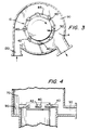
- Fig. 3 shows a partially sectional schematic plan view of the rotor 30 illustrating the dynamic bar fluidizing and prescreening device.
- the bars 40 are shown here having a second, different configuration from those of Figure 1 and mounted at an angle of approximately 45 degrees to the radius of the rotor. This actual angle is determined by the speed of the rotor and the mass of the objects which the dynamic bar screen is designed to remove.
- the pulp suspension is tangentially fed through suspension inlet 120 and into the inlet chamber 70, and tramp material separated by the rotary motion is removed by way of heavy and large material trap 90.
- the non-apertured screen extension 14 forms the boundary between trap 90 and feed deflocculating and accelerating zone passage 82.
- FIG. 4 shows an alternative embodiment of the rotor of Fig. 3 in a sectional schematic elevation view.
- the angled face 42 of bars 40 and the radial extension of bars to cover the entrance to annular passage 82 can be seen.
- the fibrous material/liquid suspension enters fine screen housing 60 through suspension inlet 120 in a tangential direction into inlet chamber 70.
- This entry direction imparts a rotational motion to the suspension and reduces the amount of energy necessary to accelerate the suspension to the proper screening velocity.
- An additional feature of the tangential entry is that it imparts centrifugal force to some large heavy objects which will tend to pass into heavy and large material trap 90.
- the suspension then enters passage 82 at the entrance of which it is acted upon by bars 40 of the dynamic bar screen device.
- bars 40 in addition to generating centrifugal force, do by their spacing, angle, and velocity of rotation, exclude all solid objects larger than some limit size from entering passage 82 and screening chamber 85 by striking them and deflecting them and driving them upward and outward so that such solid objects pass into trap 90. Bars 40 also deflocculate the suspension so that it will pass through passage 82 into screening chamber 85 in a condition conducive to efficient screening.
- the length of passage 82 is determined by the nature of the pulp being screened - short passage for softwood pulp and long passage for hardwood pulp.
- the central cylindrical section 34 of rotor 30 is shown as having a significant vertical dimension in Figs. 1 and 2. This conforms with the generally preferred rotor configuration having five regions disposed along its axis. In fact, this section may be a mere line at the intersection of frustoconical sections 32 and 33, or it may be a smooth curve joining the two conical sections. The actual dimension and nature of that section is empirically determined for the application intended. The main limitation on its length is the thickening tendency of the suspension being treated. At some axial level of screening chamber 85, thickening reaches its maximum tolerable extent. From this point downward, frustoconical section 33 of rotor 30 begins its taper inward.
- This taper induces recirculation flow of rejects and dilution liquid, introduced, for example, as shown, through dilution liquid inlet 105 and through rejects chamber 80, upward into screening chamber 85 where it counteracts thickening of the fibrous material/liquid suspension being screened.
- dilution liquid inlet 105 As the suspension travels down apertured portion 11 of screen 10 the fiber content is decreasing along with the liquid content. Therefore, the consistency remains approximately the same.
- the induced upward flow of dilution liquid is included a number of good acceptable fibers with unacceptable rejects fiber bundles which are rescreened in the lower portion of screening chamber 85.
- this invention provides high efficiency fractionation of fibers primarily due to the control of thickening in the screening process through use of the pumping action of the tapered regions of the rotor.
- this invention results in a larger portion of the acceptable fibers contained in the feed suspension being accepted than is possible with conventional screening systems.
Claims (7)
- Appareil sous pression de filtration d'une suspension d'un liquide et d'une matière fibreuse, pour la séparation de sa fraction fibreuse en une partie acceptée et une partie rejetée, comprenant :
un boîtier (60) ayant une entrée (120) de suspension fibreuse, un piège (90) pour les matériaux lourds et gros, une sortie (110) de partie acceptée, une sortie (100) de partie rejetée, et une entrée (105) de liquide de dilution,
une grille cylindrique creuse (10) ayant une partie supérieure ouverte communiquant avec l'entrée de suspension fibreuse, des perforations (15) dans lesquelles les fibres de la partie acceptée peuvent s'écouler vers la sortie de la partie acceptée, et une partie inférieure ouverte qui communique avec la sortie de matière acceptée et l'entrée de liquide de dilution,
un dispositif destiné à séparer le boîtier en une chambre d'entrée (70), une chambre de filtration (85), une chambre de partie acceptée (75) et une chambre de partie rejetée (80),
un rotor (30) ayant une partie supérieure fermée et une longueur supérieure à celle de la grille, le rotor étant monté coaxialement dans la grille et étant placé radialement à distance de la grille afin qu'il forme une chambre de filtration de la suspension,
un dispositif (36, 38) de création de déplacements hydrodynamiques et d'impulsions résultantes dans la suspension fibreuse contre la grille afin que le rendement de séparation soit accru, et
un dispositif (40) destiné à diriger des objets lourds et gros dans le piège (90) et à défloculer la suspension d'alimentation, caractérisé en ce que le rotor (30) a au moins quatre régions et un dispositif (32, 33) destiné à empêcher l'épaississement de la suspension fibreuse et à maintenir une consistance pratiquement constante de suspension dans la chambre de filtration, le dispositif (32, 33) étant formé par le rotor qui a deux tronçons tronconiques opposés (32, 33) formant deux des régions partant d'un tronçon cylindrique central (34) pour la création d'un effet de pompage qui aspire le liquide dans la chambre de filtration d'une part et le liquide de dilution transmis par l'entrée de liquide de dilution afin que la tendance à l'épaississement d'autre part soit compensée. - Appareil selon la revendication 1, dans lequel le dispositif destiné à diviser le boîtier comprend des flasques coopérants (62, 12) formés sur le boîtier et la grille respectivement.
- Appareil selon la revendication 1 ou 2, dans lequel le dispositif destiné à créer des impulsions hydrodynamiques comporte un arrangement de saillies (36) et de cavités (38) placées à la surface circonférentielle du rotor.
- Appareil selon l'une quelconque des revendications précédentes, dans lequel le dispositif destiné à diriger des objets gros et lourds dans le piège comporte une entrée tangentielle (120) de suspension fibreuse qui favorise l'écoulement circulaire de la suspension, et un mouvement du rotor qui accélère l'écoulement de la suspension et augmente les forces centrifuges.
- Appareil selon l'une quelconque des revendications précédentes, dans lequel le dispositif destiné à diriger les objets gros et lourds dans le piège et à défloculer la suspension fibreuse d'alimentation comporte une grille préalable de fluidisation dynamique (40) fixée à l'extrémité d'entrée du rotor (30) afin qu'elle balaie pratiquement toute l'entrée de la chambre de filtration (85), qu'elle dévie les objets dont la dimension dépasse une valeur de seuil vers l'extérieur et vers le piège et qu'elle déflocule la suspension fibreuse d'alimentation.
- Appareil selon la revendication 5, dans lequel la grille préalable de fluidisation dynamique (40) comporte plusieurs barres (40) montées au centre, disposées en direction pratiquement radiale dans le canal d'écoulement de fluide, le piège (90) entourant le canal d'écoulement de fluide et étant placé en amont et radialement à l'extérieur des barres montées au centre, et dans lequel, suivant la longueur et l'espacement des barres et leur vitesse de rotation, les barres agissent comme une grille pour limiter la dimension des objets qui peuvent passer dans le canal par frappe des objets relativement gros et projection de ceux-ci radialement vers l'extérieur et vers le haut et dans le piège (90).
- Appareil selon la revendication 6, dans lequel les barres rigides (40) sont montées sur une première région du rotor (30) si bien qu'elles dépassent radialement à l'extérieur du rotor avec un angle négatif de dégagement par rapport à la direction de rotation.
Applications Claiming Priority (2)
| Application Number | Priority Date | Filing Date | Title |
|---|---|---|---|
| US07/570,859 US5096127A (en) | 1990-08-22 | 1990-08-22 | Apparatus for pressurized screening of a fibrous material liquid suspension |
| US570859 | 1990-08-22 |
Publications (2)
| Publication Number | Publication Date |
|---|---|
| EP0473354A1 EP0473354A1 (fr) | 1992-03-04 |
| EP0473354B1 true EP0473354B1 (fr) | 1995-10-18 |
Family
ID=24281350
Family Applications (1)
| Application Number | Title | Priority Date | Filing Date |
|---|---|---|---|
| EP91307687A Expired - Lifetime EP0473354B1 (fr) | 1990-08-22 | 1991-08-21 | Appareil de tamissage sous pression d'une suspension de fibres liquides |
Country Status (9)
| Country | Link |
|---|---|
| US (1) | US5096127A (fr) |
| EP (1) | EP0473354B1 (fr) |
| JP (1) | JPH073687A (fr) |
| AT (1) | ATE129302T1 (fr) |
| BR (1) | BR9103592A (fr) |
| CA (1) | CA2049443C (fr) |
| DE (1) | DE69113932T2 (fr) |
| ES (1) | ES2078453T3 (fr) |
| FI (1) | FI913945A (fr) |
Cited By (1)
| Publication number | Priority date | Publication date | Assignee | Title |
|---|---|---|---|---|
| US7491296B2 (en) | 2002-06-07 | 2009-02-17 | Metso Paper, Inc. | Multi-stage screening apparatus, screen basket and method for screening pulp suspensions |
Families Citing this family (24)
| Publication number | Priority date | Publication date | Assignee | Title |
|---|---|---|---|---|
| US5298016A (en) * | 1992-03-02 | 1994-03-29 | Advanced Haemotechnologies | Apparatus for separating plasma and other wastes from blood |
| US5397469A (en) * | 1993-06-01 | 1995-03-14 | Ingersoll-Rand Company | Junk separator for, and in combination wtih, a pulp slurry inlet chamber of a pulp handling machine |
| SE507481C2 (sv) * | 1996-05-02 | 1998-06-15 | Alfa Laval Ab | Anordning för separering av föroreningar från fibermassasuspensioner |
| SE509134C2 (sv) * | 1997-04-14 | 1998-12-07 | Sunds Defibrator Ind Ab | Silanordning med rejektutspädning |
| SE509289C2 (sv) * | 1997-04-14 | 1999-01-11 | Sunds Defibrator Ind Ab | Silanordning med rejektförstrypning |
| JP3435346B2 (ja) * | 1998-04-16 | 2003-08-11 | 相川鉄工株式会社 | スクリーン装置 |
| FR2790270B1 (fr) * | 1999-02-26 | 2001-11-16 | Lamort E & M | Procedes et moyens pour la filtration de la pate a papier |
| DE19911884A1 (de) * | 1999-03-17 | 2000-09-21 | Voith Sulzer Papiertech Patent | Drucksortierer zum Sieben einer Papierfaserstoffsuspension und Siebräumer für einen solchen |
| SE9901148L (sv) | 1999-03-29 | 2000-06-12 | Valmet Fibertech Ab | Silanordning med ett roterbart och ett stationärt silorgan |
| SE514071C2 (sv) | 1999-04-08 | 2000-12-18 | Valmet Fibertech Ab | Silanordning med axiellt förskjutbar spaltring |
| AT408773B (de) * | 2000-02-03 | 2002-03-25 | Andritz Ag Maschf | Sieb und verfahren zur herstellung eines derartigen siebes |
| AT408770B (de) * | 2000-02-03 | 2002-03-25 | Andritz Ag Maschf | Sortierer zur reinigung einer faserstoffsuspension |
| DE10233364C1 (de) * | 2002-07-23 | 2003-12-24 | Voith Paper Patent Gmbh | Drucksortierer zum Sieben einer Faserstoffsuspension |
| AT413391B (de) * | 2003-03-27 | 2006-02-15 | Andritz Ag Maschf | Sortierer zur reinigung einer fasersuspension |
| AT413390B (de) * | 2003-03-27 | 2006-02-15 | Andritz Ag Maschf | Sortierer zur reinigung einer fasersuspension |
| US6942104B2 (en) * | 2003-09-02 | 2005-09-13 | Gl&V Management Hungary Kft. | Rotor with multiple foils for screening apparatus for papermaking pulp |
| EP1749923B1 (fr) * | 2005-08-04 | 2012-11-21 | Voith Patent GmbH | Dispositif pour traiter une suspension de fibres |
| JP4909693B2 (ja) * | 2006-07-24 | 2012-04-04 | 相川鉄工株式会社 | スクリーン装置 |
| FI120978B (fi) * | 2007-03-30 | 2010-05-31 | Advanced Fiber Tech Aft Trust | Seulalaitteen roottorielementti ja roottori |
| EP2547824B1 (fr) * | 2010-03-16 | 2018-07-18 | Tampulping OY | Filtre sous pression |
| US20120318721A1 (en) * | 2011-06-20 | 2012-12-20 | Gallagher Brian J | Grooved screen used in a tramp material separator |
| CN104233896B (zh) * | 2014-09-02 | 2016-07-06 | 郑州运达造纸设备有限公司 | 一种用于压力筛的稀释装置 |
| FI126520B (en) * | 2016-03-16 | 2017-01-31 | Red Wire Oy | Method of screening and screening device |
| KR101771371B1 (ko) * | 2016-12-26 | 2017-08-24 | 나성주 | 제지 원료 정선을 위한 스크린 머신, 스크린 머신용 케이싱 바디 및 스크린 바스켓 |
Family Cites Families (16)
| Publication number | Priority date | Publication date | Assignee | Title |
|---|---|---|---|---|
| CA631961A (en) * | 1961-11-28 | Koehring-Waterous Ltd. | Pulp screening mechanism | |
| US2908390A (en) * | 1958-01-28 | 1959-10-13 | John P Rich | Apparatus for screening pulp |
| US3437204A (en) * | 1965-12-27 | 1969-04-08 | Bird Machine Co | Screening apparatus |
| US3458038A (en) * | 1966-06-02 | 1969-07-29 | Ingersoll Rand Canada | Screening apparatus |
| DE2701737B2 (de) * | 1977-01-18 | 1980-03-20 | Hermann Finckh Maschinenfabrik Gmbh & Co, 7417 Pfullingen | Verfahren zum Aufbereiten und Reinigen von Fasermaterial sowie Anlage zur Durchführung eines solchen Verfahrens |
| US4136018A (en) * | 1977-11-10 | 1979-01-23 | Beloit Corporation | Vortex separator with coaxial inlet and lightweight reject pipelines |
| US4267035A (en) * | 1979-08-27 | 1981-05-12 | The Black Clawson Company | Pressurized rotary screening apparatus |
| DE3109196A1 (de) * | 1981-03-11 | 1982-10-14 | O & K Orenstein & Koppel Ag, 1000 Berlin | Frachtschiff fuer kuehlladung |
| US4462901A (en) * | 1981-12-28 | 1984-07-31 | Gauld W Thomas | Apparatus for screening fibrous stock |
| DE3572928D1 (en) * | 1984-12-25 | 1989-10-19 | Mitsubishi Heavy Ind Ltd | Pressure slit screen |
| SE444962B (sv) * | 1985-07-08 | 1986-05-20 | Kamyr Ab | Anordning for avskiljning av i en fibermassa forekommande icke onskverda partiklar |
| US4749474A (en) * | 1986-08-27 | 1988-06-07 | Ingersoll-Rand Company | Screening apparatus |
| FI77279C (fi) * | 1987-04-30 | 1989-02-10 | Ahlstroem Oy | Foerfarande och anordning foer behandling av fibersuspension. |
| SE458037C (sv) * | 1987-07-03 | 1990-05-03 | Kamyr Ab | Apparat foer uppdelning av en suspension av fiberhaltig cellulosamassa |
| SE458036C (sv) * | 1987-07-03 | 1990-05-03 | Kamyr Ab | Apparat foer uppdelning av en suspension av fiberhaltig cellulosamassa |
| DE3904960A1 (de) * | 1989-02-18 | 1990-08-23 | Finckh Maschf | Geraet zum sortieren und entstippen von fasersuspensionen |
-
1990
- 1990-08-22 US US07/570,859 patent/US5096127A/en not_active Expired - Fee Related
-
1991
- 1991-08-19 CA CA002049443A patent/CA2049443C/fr not_active Expired - Fee Related
- 1991-08-21 ES ES91307687T patent/ES2078453T3/es not_active Expired - Lifetime
- 1991-08-21 BR BR919103592A patent/BR9103592A/pt not_active IP Right Cessation
- 1991-08-21 EP EP91307687A patent/EP0473354B1/fr not_active Expired - Lifetime
- 1991-08-21 AT AT91307687T patent/ATE129302T1/de not_active IP Right Cessation
- 1991-08-21 FI FI913945A patent/FI913945A/fi unknown
- 1991-08-21 DE DE69113932T patent/DE69113932T2/de not_active Expired - Fee Related
- 1991-08-22 JP JP3210546A patent/JPH073687A/ja active Pending
Cited By (1)
| Publication number | Priority date | Publication date | Assignee | Title |
|---|---|---|---|---|
| US7491296B2 (en) | 2002-06-07 | 2009-02-17 | Metso Paper, Inc. | Multi-stage screening apparatus, screen basket and method for screening pulp suspensions |
Also Published As
| Publication number | Publication date |
|---|---|
| FI913945A (fi) | 1992-02-23 |
| ATE129302T1 (de) | 1995-11-15 |
| DE69113932D1 (de) | 1995-11-23 |
| FI913945A0 (fi) | 1991-08-21 |
| EP0473354A1 (fr) | 1992-03-04 |
| CA2049443A1 (fr) | 1992-02-23 |
| CA2049443C (fr) | 1996-08-06 |
| BR9103592A (pt) | 1992-05-12 |
| DE69113932T2 (de) | 1996-05-23 |
| ES2078453T3 (es) | 1995-12-16 |
| JPH073687A (ja) | 1995-01-06 |
| US5096127A (en) | 1992-03-17 |
Similar Documents
| Publication | Publication Date | Title |
|---|---|---|
| EP0473354B1 (fr) | Appareil de tamissage sous pression d'une suspension de fibres liquides | |
| EP0289020B1 (fr) | Procédé et dispositif pour le traitement d'une suspension de fibres | |
| US4880540A (en) | Pulp screening apparatus | |
| US4594152A (en) | Method and an apparatus for treating fibre suspensions | |
| US3912622A (en) | Screening machine with lights removal | |
| CA1278777C (fr) | Tamis | |
| US5566835A (en) | Cleaner with inverted hydrocyclone | |
| US5172813A (en) | Method and an apparatus for treating fiber suspension | |
| EP0771375B1 (fr) | Procede et dispositif de criblage de fibres en suspension | |
| EP0693976A1 (fr) | Epurateur de pate a papier | |
| EP0306022B1 (fr) | Procédé et dispositif pour classer une suspension de fibre | |
| EP0650542B1 (fr) | Appareil d'epuration de pate de fabrication de papier | |
| US5224603A (en) | Apparatus for treating fiber suspension | |
| CA2700264C (fr) | Appareil pour cribler des suspensions fibreuses | |
| EP0294832B1 (fr) | Appareil pour l'épuration de pâte | |
| US5925249A (en) | Screening arrangement | |
| US5143220A (en) | Apparatus for screening to remove knots from a fluid borne slurry of fibers and knots | |
| EP1184509B1 (fr) | Classeur pour suspension fibreuse | |
| US4222863A (en) | Screening apparatus and method | |
| EP0275967B1 (fr) | Procédé et dispositif pour séparer les noeuds | |
| US5323913A (en) | Pressure screening apparatus with baffle | |
| MXPA01001294A (es) | Criba. | |
| MXPA01001293A (es) | Criba. | |
| EP1159482B1 (fr) | Dispositif de tamisage | |
| WO2004046457A1 (fr) | Procede et appareil de traitement d'une suspension fibreuse |
Legal Events
| Date | Code | Title | Description |
|---|---|---|---|
| PUAI | Public reference made under article 153(3) epc to a published international application that has entered the european phase |
Free format text: ORIGINAL CODE: 0009012 |
|
| AK | Designated contracting states |
Kind code of ref document: A1 Designated state(s): AT DE ES FR GB IT SE |
|
| 17P | Request for examination filed |
Effective date: 19920717 |
|
| 17Q | First examination report despatched |
Effective date: 19940420 |
|
| GRAA | (expected) grant |
Free format text: ORIGINAL CODE: 0009210 |
|
| AK | Designated contracting states |
Kind code of ref document: B1 Designated state(s): AT DE ES FR GB IT SE |
|
| REF | Corresponds to: |
Ref document number: 129302 Country of ref document: AT Date of ref document: 19951115 Kind code of ref document: T |
|
| ITF | It: translation for a ep patent filed |
Owner name: JACOBACCI & PERANI S.P.A. |
|
| REF | Corresponds to: |
Ref document number: 69113932 Country of ref document: DE Date of ref document: 19951123 |
|
| REG | Reference to a national code |
Ref country code: ES Ref legal event code: FG2A Ref document number: 2078453 Country of ref document: ES Kind code of ref document: T3 |
|
| ET | Fr: translation filed | ||
| PLBE | No opposition filed within time limit |
Free format text: ORIGINAL CODE: 0009261 |
|
| STAA | Information on the status of an ep patent application or granted ep patent |
Free format text: STATUS: NO OPPOSITION FILED WITHIN TIME LIMIT |
|
| 26N | No opposition filed | ||
| PGFP | Annual fee paid to national office [announced via postgrant information from national office to epo] |
Ref country code: GB Payment date: 19980713 Year of fee payment: 8 |
|
| REG | Reference to a national code |
Ref country code: GB Ref legal event code: 732E |
|
| REG | Reference to a national code |
Ref country code: ES Ref legal event code: PC2A |
|
| PGFP | Annual fee paid to national office [announced via postgrant information from national office to epo] |
Ref country code: AT Payment date: 19990728 Year of fee payment: 9 |
|
| PGFP | Annual fee paid to national office [announced via postgrant information from national office to epo] |
Ref country code: ES Payment date: 19990817 Year of fee payment: 9 |
|
| PG25 | Lapsed in a contracting state [announced via postgrant information from national office to epo] |
Ref country code: GB Free format text: LAPSE BECAUSE OF NON-PAYMENT OF DUE FEES Effective date: 19990821 |
|
| PGFP | Annual fee paid to national office [announced via postgrant information from national office to epo] |
Ref country code: FR Payment date: 20000119 Year of fee payment: 9 |
|
| REG | Reference to a national code |
Ref country code: FR Ref legal event code: TP |
|
| GBPC | Gb: european patent ceased through non-payment of renewal fee |
Effective date: 19990821 |
|
| PGFP | Annual fee paid to national office [announced via postgrant information from national office to epo] |
Ref country code: DE Payment date: 20000802 Year of fee payment: 10 |
|
| PG25 | Lapsed in a contracting state [announced via postgrant information from national office to epo] |
Ref country code: AT Free format text: LAPSE BECAUSE OF NON-PAYMENT OF DUE FEES Effective date: 20000821 |
|
| PG25 | Lapsed in a contracting state [announced via postgrant information from national office to epo] |
Ref country code: ES Free format text: LAPSE BECAUSE OF NON-PAYMENT OF DUE FEES Effective date: 20000822 |
|
| PG25 | Lapsed in a contracting state [announced via postgrant information from national office to epo] |
Ref country code: FR Free format text: LAPSE BECAUSE OF NON-PAYMENT OF DUE FEES Effective date: 20010430 |
|
| REG | Reference to a national code |
Ref country code: FR Ref legal event code: ST |
|
| PGFP | Annual fee paid to national office [announced via postgrant information from national office to epo] |
Ref country code: SE Payment date: 20010802 Year of fee payment: 11 |
|
| PG25 | Lapsed in a contracting state [announced via postgrant information from national office to epo] |
Ref country code: DE Free format text: LAPSE BECAUSE OF NON-PAYMENT OF DUE FEES Effective date: 20020501 |
|
| PG25 | Lapsed in a contracting state [announced via postgrant information from national office to epo] |
Ref country code: SE Free format text: LAPSE BECAUSE OF NON-PAYMENT OF DUE FEES Effective date: 20020822 |
|
| EUG | Se: european patent has lapsed | ||
| REG | Reference to a national code |
Ref country code: ES Ref legal event code: FD2A Effective date: 20010911 |
|
| PG25 | Lapsed in a contracting state [announced via postgrant information from national office to epo] |
Ref country code: IT Free format text: LAPSE BECAUSE OF NON-PAYMENT OF DUE FEES;WARNING: LAPSES OF ITALIAN PATENTS WITH EFFECTIVE DATE BEFORE 2007 MAY HAVE OCCURRED AT ANY TIME BEFORE 2007. THE CORRECT EFFECTIVE DATE MAY BE DIFFERENT FROM THE ONE RECORDED. Effective date: 20050821 |