EP0472479B1 - Dispositif ultrasonique pour la production en continu de particules - Google Patents
Dispositif ultrasonique pour la production en continu de particules Download PDFInfo
- Publication number
- EP0472479B1 EP0472479B1 EP91420290A EP91420290A EP0472479B1 EP 0472479 B1 EP0472479 B1 EP 0472479B1 EP 91420290 A EP91420290 A EP 91420290A EP 91420290 A EP91420290 A EP 91420290A EP 0472479 B1 EP0472479 B1 EP 0472479B1
- Authority
- EP
- European Patent Office
- Prior art keywords
- ultrasonic device
- vibrating surface
- vibrating
- intermediate chamber
- channels
- Prior art date
- Legal status (The legal status is an assumption and is not a legal conclusion. Google has not performed a legal analysis and makes no representation as to the accuracy of the status listed.)
- Expired - Lifetime
Links
- 238000010924 continuous production Methods 0.000 title claims abstract description 5
- 239000007788 liquid Substances 0.000 claims abstract description 30
- 239000000463 material Substances 0.000 claims abstract description 27
- 239000002245 particle Substances 0.000 claims abstract description 7
- 239000011325 microbead Substances 0.000 claims description 9
- 238000009826 distribution Methods 0.000 claims description 6
- 238000004519 manufacturing process Methods 0.000 claims description 4
- 238000000034 method Methods 0.000 claims description 3
- 230000001105 regulatory effect Effects 0.000 claims description 3
- 238000001816 cooling Methods 0.000 claims description 2
- 230000005484 gravity Effects 0.000 claims description 2
- 239000012768 molten material Substances 0.000 description 9
- 239000002184 metal Substances 0.000 description 5
- 229910052751 metal Inorganic materials 0.000 description 5
- 230000000694 effects Effects 0.000 description 4
- 239000011344 liquid material Substances 0.000 description 4
- 230000015572 biosynthetic process Effects 0.000 description 2
- 239000002537 cosmetic Substances 0.000 description 2
- 239000011261 inert gas Substances 0.000 description 2
- 229910052500 inorganic mineral Inorganic materials 0.000 description 2
- 230000001788 irregular Effects 0.000 description 2
- 238000003754 machining Methods 0.000 description 2
- 239000011707 mineral Substances 0.000 description 2
- 230000002093 peripheral effect Effects 0.000 description 2
- 239000007787 solid Substances 0.000 description 2
- 239000007921 spray Substances 0.000 description 2
- 239000000443 aerosol Substances 0.000 description 1
- 230000033228 biological regulation Effects 0.000 description 1
- -1 but also pharmacy Substances 0.000 description 1
- 230000000295 complement effect Effects 0.000 description 1
- 230000001276 controlling effect Effects 0.000 description 1
- 230000001419 dependent effect Effects 0.000 description 1
- 239000006185 dispersion Substances 0.000 description 1
- 239000003814 drug Substances 0.000 description 1
- 229940079593 drug Drugs 0.000 description 1
- 238000005516 engineering process Methods 0.000 description 1
- 239000000446 fuel Substances 0.000 description 1
- 230000004927 fusion Effects 0.000 description 1
- 239000008187 granular material Substances 0.000 description 1
- 238000010438 heat treatment Methods 0.000 description 1
- 230000001939 inductive effect Effects 0.000 description 1
- 239000002502 liposome Substances 0.000 description 1
- 239000011159 matrix material Substances 0.000 description 1
- 238000002844 melting Methods 0.000 description 1
- 230000008018 melting Effects 0.000 description 1
- 150000002739 metals Chemical class 0.000 description 1
- 239000011859 microparticle Substances 0.000 description 1
- 230000004048 modification Effects 0.000 description 1
- 238000012986 modification Methods 0.000 description 1
- 230000010355 oscillation Effects 0.000 description 1
- 230000003071 parasitic effect Effects 0.000 description 1
- 239000000843 powder Substances 0.000 description 1
- 230000002250 progressing effect Effects 0.000 description 1
- 238000005245 sintering Methods 0.000 description 1
- 239000011343 solid material Substances 0.000 description 1
- 238000003892 spreading Methods 0.000 description 1
- 230000006641 stabilisation Effects 0.000 description 1
- 238000011105 stabilization Methods 0.000 description 1
- 239000000725 suspension Substances 0.000 description 1
- 238000002604 ultrasonography Methods 0.000 description 1
- 210000003462 vein Anatomy 0.000 description 1
Images

Classifications
-
- B—PERFORMING OPERATIONS; TRANSPORTING
- B01—PHYSICAL OR CHEMICAL PROCESSES OR APPARATUS IN GENERAL
- B01J—CHEMICAL OR PHYSICAL PROCESSES, e.g. CATALYSIS OR COLLOID CHEMISTRY; THEIR RELEVANT APPARATUS
- B01J2/00—Processes or devices for granulating materials, e.g. fertilisers in general; Rendering particulate materials free flowing in general, e.g. making them hydrophobic
- B01J2/18—Processes or devices for granulating materials, e.g. fertilisers in general; Rendering particulate materials free flowing in general, e.g. making them hydrophobic using a vibrating apparatus
-
- B—PERFORMING OPERATIONS; TRANSPORTING
- B05—SPRAYING OR ATOMISING IN GENERAL; APPLYING FLUENT MATERIALS TO SURFACES, IN GENERAL
- B05B—SPRAYING APPARATUS; ATOMISING APPARATUS; NOZZLES
- B05B17/00—Apparatus for spraying or atomising liquids or other fluent materials, not covered by the preceding groups
- B05B17/04—Apparatus for spraying or atomising liquids or other fluent materials, not covered by the preceding groups operating with special methods
- B05B17/06—Apparatus for spraying or atomising liquids or other fluent materials, not covered by the preceding groups operating with special methods using ultrasonic or other kinds of vibrations
- B05B17/0607—Apparatus for spraying or atomising liquids or other fluent materials, not covered by the preceding groups operating with special methods using ultrasonic or other kinds of vibrations generated by electrical means, e.g. piezoelectric transducers
- B05B17/0623—Apparatus for spraying or atomising liquids or other fluent materials, not covered by the preceding groups operating with special methods using ultrasonic or other kinds of vibrations generated by electrical means, e.g. piezoelectric transducers coupled with a vibrating horn
- B05B17/063—Apparatus for spraying or atomising liquids or other fluent materials, not covered by the preceding groups operating with special methods using ultrasonic or other kinds of vibrations generated by electrical means, e.g. piezoelectric transducers coupled with a vibrating horn having an internal channel for supplying the liquid or other fluent material
-
- B—PERFORMING OPERATIONS; TRANSPORTING
- B05—SPRAYING OR ATOMISING IN GENERAL; APPLYING FLUENT MATERIALS TO SURFACES, IN GENERAL
- B05B—SPRAYING APPARATUS; ATOMISING APPARATUS; NOZZLES
- B05B17/00—Apparatus for spraying or atomising liquids or other fluent materials, not covered by the preceding groups
- B05B17/04—Apparatus for spraying or atomising liquids or other fluent materials, not covered by the preceding groups operating with special methods
- B05B17/06—Apparatus for spraying or atomising liquids or other fluent materials, not covered by the preceding groups operating with special methods using ultrasonic or other kinds of vibrations
- B05B17/0607—Apparatus for spraying or atomising liquids or other fluent materials, not covered by the preceding groups operating with special methods using ultrasonic or other kinds of vibrations generated by electrical means, e.g. piezoelectric transducers
- B05B17/0623—Apparatus for spraying or atomising liquids or other fluent materials, not covered by the preceding groups operating with special methods using ultrasonic or other kinds of vibrations generated by electrical means, e.g. piezoelectric transducers coupled with a vibrating horn
Definitions
- the present invention relates to an ultrasonic device for the continuous production of particles having a particle size as homogeneous as possible, and more particularly of micro-droplets of controlled diameter and sphericity.
- ultrasonic devices are known, such as those disclosed in the disclosures DE-A-2,537,772 or DE-A-3,036,721, which respectively describe devices having the characteristics mentioned in the preamble of claim 1, for the continuous production of micro-droplets specifically from liquid, these devices comprising a vibrating surface atomizing by their orthogonal ultrasonic vibrational regime the liquid brought in from the inside.
- these devices due to the configuration of the means for supplying the liquid into these cited devices, these only work if the liquid does not have too high a viscosity.
- the flow rate of the liquid delivered can be quite irregular and the distribution can be made in a sheet of more or less constant thickness.
- an ultrasonic device which makes it possible to obtain micro-beads having a diameter of the order of 5 to 200 microns.
- a liquid material is dropped dropwise on the end surface of a vibrator oscillating at a frequency between 5 and 50 kilohertz.
- An ultrasonic vibrator comprises, for example, a piezoelectric transducer extended by a concentrator, that is to say a part whose particular shape allows a resonance on its end surface of an order of magnitude greater than the oscillation of the transducer.
- Such a vibrating device is also called "sonotrode" in the industry.
- this process is carried out in an enclosure for controlling the atmosphere, either under vacuum or under inert gas.
- the ultrasonic device described above presents parasitic effects due to the configuration and arrangement of the elements inducing a dispersion of the diameters which is still unsatisfactory since it subsequently requires calibration of the microbeads by passing through a series of screens.
- the wave network of the liquid layer is unstable on the vibrating surface and, on the other hand, that the thickness of this tablecloth was variable, thick near the place where the material arrives and too thin towards the edges of the surface.
- the purpose of the present invention is to obviate the aforementioned drawbacks due in large part to the excessively irregular flow and distribution of the liquid on the vibrating surface, in order to produce micro-droplets of more controlled diameter with a production yield. improved.
- an ultrasonic device comprising a vibrating surface atomizing, by its orthogonal ultrasonic vibratory regime, a material in the liquid state brought from inside the device by means of supply, characterized in that the material at l liquid state is distributed to the vibrating surface by an annular channel or several channels of which one of the dimensions of the passage section is of the order of a millimeter or submillimetric, either from an intermediate chamber-crucible for regulating flow and / or thermal regulation, either directly from said annular channel acting as an intermediate crucible chamber, said intermediate chamber being underlying the vibrating surface, as well as to a method for its implementation.
- the supply means comprise one or more conduits for supplying the material in the liquid state; and the base of said intermediate chamber, where the one or more supply conduits open is located in the plane of a wave node of the vibratory regime.
- the material in the liquid state is distributed to the vibrating surface by one or more channels whose section total passage is greater than 8 mm2, the flow of the material taking place by capillarity and / or pressure gradient induced by the vibratory mode.
- material in the liquid state is meant both a liquid proper at ambient temperatures and a molten material, that is to say solid at these temperatures and made liquid for the occasion.
- This material can be mineral and / or organic. Thanks to the presence of the intermediate chamber, it becomes possible on the one hand to control the viscosity of the liquid at the level of the vibrating surface and influence its temperature, and on the other hand to better control the pressure drops by making more precise now shorter ejection channels.
- an initially solid material can be maintained in the liquid state or liquefied by heating in the intermediate chamber acting as a crucible very close to the vibrating surface.
- the internal intermediate chamber is cylindrical and parallel to the vibrating surface. Then, the material in the liquid state is distributed by several channels located at regular intervals on the line of the chamber closest to the surface.
- the internal intermediate chamber is central and has a tubular shape orthogonal to the vibrating surface into which it opens directly by one of its ends, if desired narrowed.
- the tubular internal intermediate chamber is located on the periphery of the vibrating device, underlying and orthogonal to the vibrating surface of convex shape, at the periphery of which it opens.
- the vibrating surface has a series of parallel or checkerboard grooves, or a network of circular and / or radial grooves which tend to stabilize the wave regime of the sheet in position.
- the grooves may have a rectangular, trapezoidal, U-shaped cross section, etc.
- the channels can open at an angle of between 25 and 60 degrees relative to the surface.
- a cap parallel to the surface is arranged above and close to the outlet of the channel (s).
- FIG. 1 is illustrated the end of a vibrating element 10, in this case the concentrator of a sonotrode, ending in a vibrating surface forming an atomizer 11.
- a vibrating element 10 used as an internal crucible, substantially cylindrical, the length of which is parallel to the atomizing surface 11.
- This internal intermediate chamber 22 is supplied with material in the liquid state, for example in fusion, by a channel of lead 20.
- the vibrating element 10 being heated, the molten material is also maintained at temperature inside the intermediate chamber 22.
- a series of ejection channels 24, for example of the order of 15, connects this intermediate chamber 22 at the atomizing surface 11.
- these ejection channels 24 are arranged at regular intervals along the line of the intermediate chamber closest to the surface. The diameter of each of these channels is of the order of a millimeter.
- the vibratory mode of the sonotrode induces in these channels 24 a pressure difference with the outside causing the exit of the molten material out of these channels.
- the output flow rate of the molten material is influenced by capillary effects, themselves dependent on the one hand on the ultimate shape and on the quality of the machining of the channels, and on the other hand of the rheological characteristics of the molten material depending themselves on the value of the final temperature of the material.
- the atomizing surface 11 comprises a series of parallel and regular grooves or grooves of width of the order of a millimeter, of depth of about 0.25 millimeters for a step of the order of 2 millimeters.
- the ejection channels 24 respectively open at bottom of a groove thus formed. The object of these grooves is to stabilize in a lateral position the sheet of spread material.
- a shoe is provided on the vibrating element 10, the end of which constitutes a cap 30 parallel to the atomizing surface 11, which cap arrives above the channels ejection 24.
- the shape, the dimensions and the weight of this shoe and cap 30 are obviously dimensioned to avoid an excessively sensitive modification of the vibratory regime of the vibrating element 10, in particular of the concentrator.
- the effect of the cap 30 can be replaced by the mouths of oblique ejection channels 24, that is to say opening onto the vibrating surface 11 at an angle between 15 and 75 degrees relative to this area.
- the practical realization of such bent channels is more difficult and can moreover create pressure drops within these channels.
- the flow rate of molten material on the atomizing surface 11 is established on the one hand by the passage section of each of the channels 24 and on the other hand by the number of these channels.
- Figure 2 is illustrated a second variant of the end of the sonotrode in which the main parts are coaxial with the vibrating element 60 cylindrical.
- the base of the piece 76 is located in a wave node plane, that is to say at a height of the sonotrode where the amplitude of the vibrations is minimum, thus voluntarily limiting the resonance more or less controlled of this room 76.
- the restriction 74 creates, with the upper part of the blind hole 75, a channel 72 of elongated cylindrical shape, in other words annular or toric, opening directly onto the upper atomizing surface 61.
- This annular or toric channel made here both office of internal crucible chamber and ejection channel. If the volume of this internal chamber must be greater for reasons of flow control by buffer effect, then, the restriction 74 is reduced in its upper part to constitute a narrowed ejection channel.
- a transverse supply channel 70 intersects the channel 72.
- This supply channel 70 can open into the blind hole 75 at any height, but preferably at the bottom, ie at the level of the wave node plane.
- the upper atomizer surface 61 also has a series of parallel grooves 64 of dimensions substantially identical to the grooves described in Figure 1. It may be useful to stabilize the sheet of molten material in the two axes of the plane of the surface 61, which is done by the size of complementary transverse grooves 62.
- the part 76 is supplemented, at its outer end, by a cap 80 projecting beyond the outlet of the channel 72.
- this cap 80 has the function of folding towards the atomizing surface 61 the ejected molten material .
- the blind hole 75 could have a conical mouth at the surface 61 and this at an apex angle which can vary between 30 and 150 degrees.
- the part 76 has, instead of a cap 80, a conical widening with a corresponding angle.
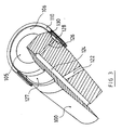
- FIG. 3 a third variant of the end of the sonotrode comprising a vibrating element 100 which is cylindrical, or even frustoconical downwards, and having in the upper part, underlying the vibrating surface 105, a peripheral groove 127 constituting , in combination with an added collar 110, an intermediate chamber 128.
- the internal diameter of the collar 110 is greater than the external diameter of the vibrating element by one to two millimeters.
- this flange 110 is fixed to the vibrating element 100 at the level of a wave node plane in order to limit possible vibrations in the manner of a bell.
- the material can be brought to the intermediate chamber 128, preferably close to the wave node, that is to say at the base of the chamber by internal channels 122, 124 and 126, or even by an external channel.
- the central channel 124 can be drilled from the underside, and the inlet is subsequently closed.
- An ejection channel 130 is formed at the periphery of the vibrating surface 105 due to the small difference between the external diameter of the vibrating element 100 and the internal diameter of the flange 110.
- the vibrating surface 105 is slightly convex, and in particular has a rounding at the outlet of the ejection channel 130. This rounding prevents any rupture of the film of liquid material progressing out of the channel radially towards the center of the surface.
- the upper edge of the collar 100 can also be slightly folded radially inwards to accompany the movement of the liquid material around the periphery of the vibrating surface.
- the external part 106 of the vibrating surface 105 also has a certain inclination, of the order of 10 to 20 degrees, relative to the horizontal, both to soften the flare at the outlet of the ejection channel, and also to orient the majority of the micro-droplets forming at this level towards the outside of the device.
- This peripheral zone 106 proving to be the most important from the point of view of the formation of microdroplets, it may be advantageous to cut in this zone a frame of radial and circular grooves for regulating the distribution of the liquid material.
- the sonotrode is installed with its vibrating surface according to the invention, in a closed enclosure allowing the surrounding environment to be controlled, that is to say working under vacuum or under inert gas.
- the vibrating element 10 of FIG. 1 is oriented at an angle of 45 degrees upwards with the supply channel 20 also oriented upwards.
- the supply channel 20 also oriented upwards.
- the metal is heated beforehand in a main crucible that l 'is then brought to the molten state in the inlet channel 20. It is found that the grooves 12 provide lateral stabilization of the sheet and, to some extent, a call for material from the channels.
- the vibrating element 60 according to FIG. 2, or the element 100 according to FIG. 3, can be installed in the enclosure with an angle between 0 and 180 degrees relative to the horizontal. Even when the element is installed at an angle greater than 90 ° , the ply always remains on the vibrating surface 61 by the effect of surface tension. This phenomenon is still verified when the vibrating surface is directed downwards. The detached micro-droplets are projected and fall directly downwards by gravity, cooling and forming micro-beads.
- the vibrating element can also be constituted by a vibrating blade, the intermediate chamber with its ejection channels then being arranged in the blade under the upper surface.
- the invention applies in the numerous fields where it is desirable to continuously manufacture particles with a particle size as homogeneous as possible and it will be useful to recall those which have been mentioned above, namely molten metals, but also pharmacy, cosmetics and motors thermal.
Landscapes
- Chemical & Material Sciences (AREA)
- Organic Chemistry (AREA)
- Chemical Kinetics & Catalysis (AREA)
- Physical Or Chemical Processes And Apparatus (AREA)
- Special Spraying Apparatus (AREA)
- Control And Other Processes For Unpacking Of Materials (AREA)
- Surgical Instruments (AREA)
- Disintegrating Or Milling (AREA)
- Formation And Processing Of Food Products (AREA)
Description
- La présente invention est relative à un dispositif ultrasonique pour la production en continu de particules ayant une granulométrie aussi homogène que possible, et plus particulièrement de micro-gouttelettes de diamètre et de sphéricité contrôlés.
- Le problème de la production de micro-gouttelettes finement divisées se rencontre dans de nombreux domaines où il est nécessaire de pulvériser ou d'atomiser des liquides organiques et/ou minéraux, par exemple dans le domaine pharmaceutique pour délivrer un produit en suspension, médicament ou autre, au moyen d'un aérosol, ou enrobé dans une matrice (médicament-retard). Dans le même ordre d'idées, on citera le domaine des cosmétiques, par exemple peur produire ce qu'il est convenu maintenant d'appeler des liposomes.
- Pour ce, on connait des dipositifs ultrasoniques, tel que ceux divulgués dans les exposés DE-A-2 537 772 ou DE-A-3 036 721, lesquels décrivent respectivement des dispositifs présentant les caractéristiques mentionnées en préambule de la revendication 1, pour la production en continu de micro-gouttelettes spécifiquement à partir de liquide, ces dispositifs comprenant une surface vibrante atomisant de par leur régime vibratoire ultrasonique orthogonal le liquide amené depuis l'intérieur. Toutefois, de par la configuration des moyens d'amenée du liquide dans ces dispositifs cités, ceux-ci ne fonctionnent que si le liquide ne présente pas une viscosité trop importante. De plus, le débit du liquide délivré peut être assez irrégulier et la distribution peut se faire en une nappe d'épaisseur plus ou moins constante.
- On connait d'autre part des carburateurs de moteurs thermiques ou des injecteurs de chaudières, tel que celui décrit dans le document EP-A-0202381, fonctionnant par ultrasons pour pulvériser un combustible liquide. A nouveau, compte-tenu des très faibles sections de passage impliquées, ces pulvérisateurs ne peuvent fonctionner correctement qu'avec des essences volatiles.
- Or, de nombreuses pièces sont réalisées actuellement à partir de poudres ou de granules métalliques de petites dimensions, notamment lors d'opérations de frittage. Le problème de la répartition granulométrique se révèle important car il est souhaitable de produire des lots de micro-billes toutes sensiblement de la même dimension.
- Dans la technologie des métaux fondus, on connait un dispositif ultrasonique qui permet d'obtenir des micro-billes ayant un diamètre de l'ordre de 5 à 200 microns. On fait tomber goutte-à-goutte un matériau à l'état liquide sur la surface d'extrémité d'un vibrateur oscillant à une fréquence comprise entre 5 et 50 kilohertz. Un vibrateur ultrasonique comprend, par exemple, un transducteur piézo-électrique prolongé par un concentrateur, c'est-à-dire une pièce dont la forme particulière permet une résonance sur sa surface d'extrémité d'un ordre de grandeur supérieur à l'oscillation du transducteur. Un tel dispositif vibrateur est également appelé "sonotrode" dans l'industrie. De préférence, ce procédé est effectué dans une enceinte permettant de contrôler l'atmosphère, soit sous vide, soit sous gaz inerte.
- Lorsqu'une goutte liquide tombe sur la surface vibrante ultrasonique, on observe sur celle-ci la formation d'une nappe dont la surface supérieure prend la forme d'un réseau d'ondes stationnaires de longueur d'onde de l'ordre de 200 microns par exemple. Quand l'amplitude de ces ondes atteint une valeur suffisante, des gouttes de liquide se détachent du sommet de ces ondes puis, en se refroidissant, forment des micro-billes solides de diamètre de l'ordre de 50 microns. On constate que le diamètre des micro-billes ainsi obtenu dépend pour une grande part de la fréquence de la vibration de la surface. La répartition des diamètres autour d'une valeur moyenne dépend en partie de l'amplitude de la vibration, mais plutôt des caractéristiques rhéologiques du matériau qui varient notablement entre un liquide et un matériau fondu. Le taux de production horaire de micro-particules dépend lui essentiellement de l'amplitude de la vibration et du coefficient de viscosité dynamique du matériau.
- Le dispositif ultrasonique décrit précédemment présente toutefois des effets parasites dûs à la configuration et à l'agencement des éléments induisant une dispersion des diamètres encore insatisfaisante car nécessitant par la suite un calibrage des micro-billes par passage dans une série de tamis. On a d'une part constaté que le réseau d'ondes de la nappe liquide est instable sur la surface vibrante et d'autre part que l'épaisseur de cette nappe était variable, épaisse proche du lieu où arrive le matériau et trop fine vers les bords de la surface.
- Le but de la présente invention est d'obvier les inconvénients précités dûs en grande partie au débit et à la distribution trop irréguliers du liquide sur la surface vibrante, et ce afin de produire des micro-gouttelettes de diamètre plus contrôlé avec un rendement de production amélioré.
- Ces buts sont atteints grâce à un dispositif ultrasonique comprenant une surface vibrante atomisant de par son régime vibratoire ultrasonique orthogonal un matériau à l'état liquide amené depuis l'intérieur du dispositif par des moyens d'amenée, caractérisé en ce que le matériau à l'état liquide est distribué à la surface vibrante par un canal annulaire ou plusieurs canaux dont l'une des dimensions de la section de passage est de l'ordre du millimètre ou submillimétrique, soit à partir d'une chambre intermédiaire-creuset de régulation de débit et/ou de régulation thermique, soit directement à partir dudit canal annulaire faisant office de chambre intermédiaire-creuset, ladite chambre intermédiaire étant sous-jacente à la surface vibrante, ainsi qu'à un procédé pour sa mise en oeuvre. Avantageusement, les moyens d'amenée comprennent un ou plusieurs conduits d'amenée du matériau à l'état liquide ; et la base de ladite chambre intermédiaire, où débouchent le ou lesdits conduits d'amenée se situe dans le plan d'un noeud d'onde du régime vibratoire.
- Utilement, le matériau à l'état liquide est distribué à la surface vibrante par un ou plusieurs canaux dont la section totale de passage est supérieure à 8 mm2, l'écoulement du matériau s'effectuant par capillarité et/ou gradient de pression induit par le mode vibratoire.
- Par "matériau à l'état liquide", on entend désigner aussi bien un liquide proprement dit aux températures ambiantes qu'un matériau fondu, c'est-à-dire solide à ces températures et rendu liquide pour la circonstance. Ce matériau peut être minéral et/ou organique. Grâce à la présence de la chambre intermédiaire, il devient possible d'une part de contrôler la viscosité du liquide au niveau de la surface vibrante en jouent sur sa température, et d'autre part de mieux maîtriser les pertes de charge par la réalisation plus précise de canaux d'éjections maintenant plus courts. Ainsi, un matériau initialement solide peut être maintenu à l'état liquide ou liquéfié par chauffage dans la chambre intermédiaire faisant office de creuset très proche de la surface vibrante.
- Selon un premier mode de réalisation préféré, la chambre intermédiaire interne est cylindrique et parallèle à la surface vibrante. Alors, le matériau à l'état liquide est distribué par plusieurs canaux situés à intervalles réguliers sur la ligne de la chambre la plus proche de la surface.
- Selon un second mode de réalisation préféré, la chambre intermédiaire interne est centrale et a une forme tubulaire orthogonale à la surface vibrante dans laquelle elle débouche directement par l'une de ses extrémités, si désiré rétrécie.
- Selon un troisième mode de réalisation préféré, la chambre intermédiaire interne tubulaire est située sur le pourtour du dispositif vibrant, sous-jacente et orthogonale à la surface vibrante de forme convexe, A la périphérie de laquelle elle débouche.
- Avantageusement, la surface vibrante présente une suite de rainures parallèles ou en damier, ou un réseau de rainures circulaires et/ou radiales qui tendent à stabiliser en position le régime ondulatoire de la nappe. Les rainures peuvent présenter une section transversale rectangulaire, trapézoïdale, en forme de U, etc...
- Afin d'améliorer l'épandage du matériau à l'état liquide sur la surface vibrante, les canaux peuvent déboucher avec un angle compris entre 25 et 60 degrés par rapport à la surface. En alternative, une coiffe parallèle à la surface est disposée au-dessus et proche de la sortie du ou des canaux.
- L'invention est décrite ci-après de façon plus détaillée à l'aide d'exemples d'exécution sans caractère limitatif illustrés aux dessins annexés dans lesquels :
- la figure 1 est une vue en perspective partiellement éclatée d'un premier mode de réalisation du dispositif ultrasonique,
- la figure 2 est une vue en perspective partiellement éclatée d'un second mode de réalisation du dispositif ultrasonique,
- la figure 3 est une vue en perspective partiellement éclatée d'un troisième mode de réalisation du dispositif ultrasonique.
- Sur la figure 1 est illustrée l'extrémité d'un élément vibrant 10, en l'occurrence du concentrateur d'une sonotrode, se terminant par une surface vibrante faisant atomiseur 11. Dans la coupe partielle de l'élément vibrant 10, on peut observer une chambre intermédiaire interne 22, utilisée en tant que creuset interne, sensiblement cylindrique dont la longueur est parallèle à la surface atomiseur 11. Cette chambre intermédiaire interne 22 est alimentée en matière à l'état liquide, par exemple en fusion, par un canal d'amenée 20. L'élément vibrant 10 étant chauffé, le matériau en fusion est maintenu en température également à l'intérieur de la chambre intermédiaire 22. Une suite de canaux d'éjections 24, par exemple de l'ordre de 15, relie cette chambre intermédiaire 22 à la surface atomiseur 11. De préférence, ces canaux d'éjection 24 sont disposés à intervalles réguliers le long de la ligne de la chambre intermédiaire la plus proche de la surface. Le diamètre de chacun de ces canaux est de l'ordre du millimètre.
- Le mode vibratoire de la sonotrode induit dans ces canaux 24 une différence de pression avec l'extérieur provoquant la sortie du matériau en fusion hors de ces canaux. Compte-tenu de la faible section de passage de chacun de ces canaux, le débit de sortie du matériau en fusion est influencé par des effets de capillarité, eux-mêmes dépendants d'une part de la forme ultime et de la qualité de l'usinage des canaux, et d'autre part des caractéristiques rhéologiques du matériau en fusion dépendant ellesmêmes de la valeur de la température finale du matériau.
- Comme on peut bien l'observer sur la figure 1, la surface atomiseur 11 comporte une série de stries ou rainures parallèles et régulières de largeur de l'ordre du millimètre, de profondeur d'environ 0,25 millimètre pour un pas de l'ordre de 2 millimètres. Les canaux d'éjection 24 débouchent respectivement au fond d'une rainure ainsi constituée. L'objet de ces rainures est de stabiliser en position latérale la nappe de matériau épandu.
- Afin de limiter des projections de matériau hors de la surface vibrante 11 dès la sortie des canaux, on dispose sur l'élément vibrant 10 un sabot dont l'extrémité constitue une coiffe 30 parallèle à la surface atomiseur 11, laquelle coiffe arrive audessus des canaux d'éjection 24. La forme, les dimensions et le poids de ce sabot et coiffe 30 sont bien évidemment dimensionnés pour éviter une modification trop sensible du régime vibratoire de l'élément vibrant 10, notamment du concentrateur.
- En alternative, on peut remplacer l'effet de la coiffe 30 par des embouchures de canaux d'éjection 24 obliques, c'est-à-dire débouchant sur la surface vibrante 11 avec un angle compris entre 15 et 75 degrés par rapport à cette surface. Toutefois, la réalisation pratique de tels canaux coudés est plus difficile et peut de plus créer des pertes de charge au sein de ces canaux.
- Comme on peut s'en rendre compte, le débit de matériau en fusion sur la surface atomiseur 11 est établi d'une part par la section de passage de chacun des canaux 24 et d'autre part par le nombre de ces canaux.
- Sur la figure 2 est illustrée une seconde variante de l'extrémité de la sonotrode dans laquelle les pièces principales sont coaxiales à l'élément vibrant 60 cylindrique. Pour ce, on effectue d'abord le perçage d'un trou borgne 75 au milieu de l'élément vibrant 60. On insère en force dans ce trou borgne une pièce 76 dont la partie inférieure a un diamètre correspondant à celui du trou borgne 75 et dont la partie supérieure présente une restriction 74.
- Avantageusement, la base de la pièce 76 se situe dans un plan de noeud d'onde, c'est-à-dire à une hauteur de la sonotrode où l'amplitude des vibrations est minimum, limitant ainsi volontairement la mise en résonance plus ou moins contrôlée de cette pièce 76.
- La restriction 74 crée, avec la partie supérieure du trou borgne 75, un canal 72 de forme cylindrique allongée, en d'autres termes annulaire ou torique, débouchant directement sur la surface supérieure atomiseur 61. Ce canal annulaire ou torique fait ici à la fois office de chambre interne-creuset et de canal d'éjection. Si le volume de cette chambre interne doit être supérieur pour des raisons de régulation de débit par effet tampon, alors, la restriction 74 est réduite dans sa partie supérieure pour constituer un canal d'éjection rétréci.
- Un canal d'amenée 70 transversal intersecte le canal 72. Ce canal d'amenée 70 peut déboucher dans le trou borgne 75 à n'importe quelle hauteur, mais de préférence au fond, soit au niveau du plan de noeud d'onde.
- Comme on peut le constater sur la figure 2, la surface supérieure atomiseur 61 présente également une suite de rainures parallèles 64 de dimensions sensiblement identiques aux rainures décrites sur la figure 1. Il peut s'avérer utile de stabiliser la nappe de matériau en fusion dans les deux axes du plan de la surface 61, ce que l'on effectue par la taille de rainures complémentaires transversales 62.
- Par ailleurs, la pièce 76 est complétée, en son extrémité extérieure, par une coiffe 80 débordant au-delà de la sortie du canal 72. Comme précédemment, cette coiffe 80 a pour fonction de rabattre vers la surface atomiseur 61 le matériau en fusion éjecté. En alternative, le trou borgne 75 pourrait présenter une embouchure conique au niveau de la surface 61 et ce d'un angle au sommet pouvant varier entre 30 et 150 degrés. Alors, la pièce 76 présente, au lieu d'une coiffe 80, un élargissement conique d'angle correspondant.
- Sur la figure 3 est illustrée une troisième variante de l'extrémité de la sonotrode comprenant un élément vibrant 100 cylindrique, voire tronconique vers le bas, et présentant dans la partie supérieure, sous-jacente à la surface vibrante 105, une rainure périphérique 127 constituant, en combinaison avec une collerette 110 rapportée, une chambre intermédiaire 128. Le diamètre interne de la collerette 110 est supérieur au diamètre externe de l'élément vibrant d'un à deux millimètres. De préférence, cette collerette 110 est fixée à l'élément vibrant 100 au niveau d'un plan de noeud d'onde pour limiter d'éventuelles vibrations à la manière d'une cloche.
- Le matériau peut être amené jusqu'à la chambre intermédiaire 128, de préférence proche du noeud d'onde, c'est-à-dire à la base de la chambre par des canaux internes 122, 124 et 126, voire par un canal externe. Pour des considérations d'usinage, le canal central 124 peut être percé à partir de la face inférieure, et l'orifice d'entrée est par la suite refermé.
- Un canal d'éjection 130 est formé à la périphérie de la surface vibrante 105 de par la faible différence entre le diamètre externe de l'élément vibrant 100 et le diamètre interne de la collerette 110. Comme on peut l'observer sur la figure 3, la surface vibrante 105 est légèrement convexe, et présente notamment un arrondi au niveau de la sortie du canal d'éjection 130. Cet arrondi évite toute rupture du film de matériau liquide progressant hors du canal radialement vers le centre de la surface. Si nécessaire, le bord supérieur de la collerette 100 peut aussi être légèrement replié radialement vers l'intérieur pour accompagner le mouvement du matériau liquide sur le pourtour de la surface vibrante.
- La partie externe 106 de la surface vibrante 105 présente aussi une certaine inclinaison, de l'ordre de 10 à 20 degrés, par rapport à l'horizontale, à la fois pour adoucir l'arrondi à la sortie du canal d'éjection, et aussi pour orienter la majorité des micro-gouttelettes se formant à ce niveau vers l'extérieur du dispositif. Cette zone periphérique 106 s'avérant être la plus importante au point de vue de la formation de microgouttellettes, il peut être avantageux de tailler dans cette zone une trame de rainures radiales et circulaires de régulation de la répartition du matériau liquide.
- Comme on peut aisément le comprendre, on installe la sonotrode avec sa surface vibrante selon l'invention, dans une enceinte close permettant de contrôler le milieu environnant, c'est-à-dire travailler sous vide ou sous gaz inerte.
- Avantageusement, l'élément vibrant 10 de la figure 1 est orienté d'un angle de 45 degrés vers le haut avec le canal d'amenée 20 également orienté vers le haut. On peut ainsi faire descendre par en haut un fil ou une lame liquide ou une tige de métal préchauffée dans le canal 20, ce métal fondant alors dans la chambre intermédiaire interne 22. En alternative, on chauffe le métal préalablement dans un creuset principal que l'on amène alors à l'état de fusion dans le canal d'entrée 20. On constate que les rainures 12 assurent une stabilisation latérale de la nappe et, dans une certaine mesure, un appel de matériau venant des canaux.
- L'élément vibrant 60 selon la figure 2, ou l'élément 100 selon la figure 3, peut être installé dans l'enceinte avec un angle compris entre 0 et 180 degrés par rapport à l'horizontale. Même lorsque l'élément est installé avec un angle supérieur à 90°, la nappe reste toujours sur la suface vibrante 61 par effet de tension superficielle. Ce phénomène se vérifie encore lorsque la surface vibrante est dirigée vers le bas. Les micro-gouttelettes détachées sont projetées et tombent directement par gravité vers le bas en se refroidissant et en formant des micro-billes.
- Si nécessaire, notamment pour atteindre des fréquences de vibrations plus importantes, donc des diamètres de micro-billes plus petites, l'élément vibrant peut également être constitué par une lame vibrante la chambre intermédiaire avec ses canaux d'éjection étant alors aménagés dans la lame sous la surface supérieure.
- L'invention s'applique dans les nombreux domaines où il est souhaitable de fabriquer en continu des particules de granulométrie aussi homogène que possible et on rappellera utilement ceux qui ont été cités plus haut, à savoir métaux fondus, mais aussi pharmacie, cosmétique et moteurs thermiques.
Claims (10)
- Dispositif ultrasonique pour la production en continu de micro-gouttelettes ayant une granulométrie homogène, comprenant une surface vibrante (11,61,105) atomisant de par son régime vibratoire ultrasonique orthogonal un matériau à l'état liquide amené depuis l'intérieur du dispositif par des moyens d'amenée (20,22,24; 70,72; 122,124,126,128,130), caractérisé en ce que le matériau à l'état liquide est distribué à la surface vibrante (11,61,105) par un canal annulaire (72,130) ou plusieurs canaux (24) dont l'une des dimensions de la section de passage est de l'ordre du millimètre ou submillimétrique, soit à partir d'une chambre intermédiaire-creuset (22,128) de régulation de débit et/ou de régulation thermique, soit directement à partir dudit canal annulaire (72) faisant office de chambre intermédiaire-creuset, ladite chambre intermédiaire (22,72,128) étant sous-jacente à la surface vibrante (11,61,105).
- Dispositif ultrasonique selon la revendication 1, caractérisé en ce que lesdits moyens d'amenée comprennent un ou plusieurs conduits d'amenée (20,70,126) du matériau à l'état liquide, la base de ladite chambre intermédiaire (22, 72,128), où débouchent le ou lesdits conduits d'amenée (20,76,126) se situant dans le plan d'un noeud d'onde du régime vibratoire.
- Dispositif ultrasonique selon la revendication 1 ou 2, caractérisé en ce que la section totale de passage du ou des canaux (72,130,24) est supérieure à 8 mm2, l'écoulement du matériau s'effectuant par capillarité et/ou gradient de pression induit par le mode vibratoire.
- Dispositif ultrasonique selon l'une des revendications précédentes, caractérisé en ce que les canaux débouchent sur la surface vibrante (11) avec un angle compris entre 25 et 75 degrés par rapport à la surface.
- Dispositif ultrasonique selon l'une des revendications 1 à 4, caractérisé en ce que la chambre intermédiaire interne (22) est cylindrique et parallèle à la surface vibrante (11), et en ce que le matériau à l'état liquide est distribué par plusieurs canaux (24) situés à intervalles réguliers sur la ligne de la chambre la plus proche de la surface (11).
- Dispositif ultrasonique selon l'une des revendications 1 à 4, caractérisé en ce que la chambre intermédiaire interne (72) est centrale, et a une forme tubulaire orthogonale à la surface vibrante (11) dans laquelle elle débouche directement par l'une de ses extrémités, si désiré rétrécie.
- Dispositif ultrasonique selon l'une des revendications 1 à 4, caractérisé en ce que la chambre intermédiaire interne (128) tubulaire est située sur le pourtour du dispositif vibrant (100), sous-jacente et orthogonale à la surface vibrante (105), de forme convexe parrapport audit dispositif vibrant, à la périphérie de laquelle elle débouche.
- Dispositif ultrasonique selon l'une des revendications précédentes, caractérisé en ce que la surface vibrante (11) présente un réseau de rainures rectilignes parallèles (12) ou en damier, ou un réseau de rainures circulaires et/ou radiales.
- Dispositif ultrasonique selon la revendication 8, caractérisé en ce que les rainures présentent une section transversale rectangulaire.
- Procédé de fabrication de micro-billes à partir de matériau thermofusible selon lequel on introduit le matériau dans la chambre intermédiaire-creuset d'un dispositif ultrasonique selon l'une des revendications 1 à 8 de façon à ce que ledit matériau soit amené à l'état de fusion, les micro-gouttelettes produites par le dispositif et détachées de la surface vibrante tombant par gravité en se refroidissant et en formant lesdites micro-billes.
Applications Claiming Priority (2)
| Application Number | Priority Date | Filing Date | Title |
|---|---|---|---|
| FR9010608 | 1990-08-20 | ||
| FR9010608A FR2665849B1 (fr) | 1990-08-20 | 1990-08-20 | Dispositif ultrasonique pour la production en continu de particules. |
Publications (2)
| Publication Number | Publication Date |
|---|---|
| EP0472479A1 EP0472479A1 (fr) | 1992-02-26 |
| EP0472479B1 true EP0472479B1 (fr) | 1994-12-28 |
Family
ID=9399822
Family Applications (1)
| Application Number | Title | Priority Date | Filing Date |
|---|---|---|---|
| EP91420290A Expired - Lifetime EP0472479B1 (fr) | 1990-08-20 | 1991-08-08 | Dispositif ultrasonique pour la production en continu de particules |
Country Status (12)
| Country | Link |
|---|---|
| US (1) | US5198157A (fr) |
| EP (1) | EP0472479B1 (fr) |
| JP (1) | JP3267315B2 (fr) |
| KR (1) | KR0183025B1 (fr) |
| AT (1) | ATE116161T1 (fr) |
| CA (1) | CA2049094C (fr) |
| DE (1) | DE69106278T2 (fr) |
| DK (1) | DK0472479T3 (fr) |
| ES (1) | ES2065655T3 (fr) |
| FR (1) | FR2665849B1 (fr) |
| GR (1) | GR3015394T3 (fr) |
| MY (1) | MY106813A (fr) |
Families Citing this family (58)
| Publication number | Priority date | Publication date | Assignee | Title |
|---|---|---|---|---|
| US5938117A (en) * | 1991-04-24 | 1999-08-17 | Aerogen, Inc. | Methods and apparatus for dispensing liquids as an atomized spray |
| US7628339B2 (en) | 1991-04-24 | 2009-12-08 | Novartis Pharma Ag | Systems and methods for controlling fluid feed to an aerosol generator |
| US6629646B1 (en) * | 1991-04-24 | 2003-10-07 | Aerogen, Inc. | Droplet ejector with oscillating tapered aperture |
| US6540154B1 (en) * | 1991-04-24 | 2003-04-01 | Aerogen, Inc. | Systems and methods for controlling fluid feed to an aerosol generator |
| DE4242645C2 (de) * | 1992-12-17 | 1997-12-18 | Deutsche Forsch Luft Raumfahrt | Verfahren und Einrichtung zur Herstellung von Metallkügelchen annähernd gleichen Durchmessers |
| US5545360A (en) * | 1993-06-08 | 1996-08-13 | Industrial Technology Research Institute | Process for preparing powders with superior homogeneity from aqueous solutions of metal nitrates |
| US6085740A (en) | 1996-02-21 | 2000-07-11 | Aerogen, Inc. | Liquid dispensing apparatus and methods |
| US5758637A (en) | 1995-08-31 | 1998-06-02 | Aerogen, Inc. | Liquid dispensing apparatus and methods |
| US6782886B2 (en) | 1995-04-05 | 2004-08-31 | Aerogen, Inc. | Metering pumps for an aerosolizer |
| US6014970A (en) * | 1998-06-11 | 2000-01-18 | Aerogen, Inc. | Methods and apparatus for storing chemical compounds in a portable inhaler |
| US6205999B1 (en) | 1995-04-05 | 2001-03-27 | Aerogen, Inc. | Methods and apparatus for storing chemical compounds in a portable inhaler |
| RU2130811C1 (ru) * | 1997-12-25 | 1999-05-27 | Кубанский государственный технологический университет | Ультразвуковой распылитель |
| RU2130810C1 (ru) * | 1997-12-25 | 1999-05-27 | Кубанский государственный технологический университет | Способ распыления жидких сред |
| US6235177B1 (en) | 1999-09-09 | 2001-05-22 | Aerogen, Inc. | Method for the construction of an aperture plate for dispensing liquid droplets |
| US6948491B2 (en) * | 2001-03-20 | 2005-09-27 | Aerogen, Inc. | Convertible fluid feed system with comformable reservoir and methods |
| US7600511B2 (en) * | 2001-11-01 | 2009-10-13 | Novartis Pharma Ag | Apparatus and methods for delivery of medicament to a respiratory system |
| US8336545B2 (en) * | 2000-05-05 | 2012-12-25 | Novartis Pharma Ag | Methods and systems for operating an aerosol generator |
| US7971588B2 (en) * | 2000-05-05 | 2011-07-05 | Novartis Ag | Methods and systems for operating an aerosol generator |
| MXPA02010884A (es) * | 2000-05-05 | 2003-03-27 | Aerogen Ireland Ltd | Aparato y metodo para el suministro de medicamentos al sistema respiratorio. |
| US7100600B2 (en) | 2001-03-20 | 2006-09-05 | Aerogen, Inc. | Fluid filled ampoules and methods for their use in aerosolizers |
| US6543443B1 (en) | 2000-07-12 | 2003-04-08 | Aerogen, Inc. | Methods and devices for nebulizing fluids |
| DE10059594A1 (de) * | 2000-11-30 | 2002-06-06 | Solarworld Ag | Verfahren und Vorrichtung zur Erzeugung globulärer Körner aus Reinst-Silizium mit Durchmessern von 50 mum bis 300 mum und ihre Verwendung |
| US6546927B2 (en) | 2001-03-13 | 2003-04-15 | Aerogen, Inc. | Methods and apparatus for controlling piezoelectric vibration |
| US6550472B2 (en) | 2001-03-16 | 2003-04-22 | Aerogen, Inc. | Devices and methods for nebulizing fluids using flow directors |
| US6478754B1 (en) * | 2001-04-23 | 2002-11-12 | Advanced Medical Applications, Inc. | Ultrasonic method and device for wound treatment |
| US6732944B2 (en) | 2001-05-02 | 2004-05-11 | Aerogen, Inc. | Base isolated nebulizing device and methods |
| US6554201B2 (en) | 2001-05-02 | 2003-04-29 | Aerogen, Inc. | Insert molded aerosol generator and methods |
| WO2003057291A1 (fr) | 2002-01-07 | 2003-07-17 | Aerogen, Inc. | Dispositifs et procedes pour la nebulisation de fluides d'inhalation |
| US20050205089A1 (en) * | 2002-01-07 | 2005-09-22 | Aerogen, Inc. | Methods and devices for aerosolizing medicament |
| US7677467B2 (en) * | 2002-01-07 | 2010-03-16 | Novartis Pharma Ag | Methods and devices for aerosolizing medicament |
| JP4761709B2 (ja) * | 2002-01-15 | 2011-08-31 | エアロジェン,インコーポレイテッド | エアロゾル発生器を作動するための方法およびシステム |
| US20070044792A1 (en) * | 2005-08-30 | 2007-03-01 | Aerogen, Inc. | Aerosol generators with enhanced corrosion resistance |
| US6915962B2 (en) * | 2002-05-20 | 2005-07-12 | Aerogen, Inc. | Apparatus for providing aerosol for medical treatment and methods |
| DE10327429A1 (de) * | 2003-06-18 | 2005-01-05 | Abb Patent Gmbh | Ultraschall-Stehwellen-Zerstäuberanordnung |
| US8616195B2 (en) * | 2003-07-18 | 2013-12-31 | Novartis Ag | Nebuliser for the production of aerosolized medication |
| US7267121B2 (en) | 2004-04-20 | 2007-09-11 | Aerogen, Inc. | Aerosol delivery apparatus and method for pressure-assisted breathing systems |
| US7290541B2 (en) * | 2004-04-20 | 2007-11-06 | Aerogen, Inc. | Aerosol delivery apparatus and method for pressure-assisted breathing systems |
| US7946291B2 (en) | 2004-04-20 | 2011-05-24 | Novartis Ag | Ventilation systems and methods employing aerosol generators |
| BRPI0509991A (pt) * | 2004-04-20 | 2007-10-16 | Aerogen Inc | aparelho de fornecimento em aerossol, métodos e composições para sistemas de respiração auxiliados por pressão |
| ES2296228T3 (es) * | 2004-10-12 | 2008-04-16 | S.C. JOHNSON & SON, INC. | Pulverizador automatico. |
| US8061562B2 (en) | 2004-10-12 | 2011-11-22 | S.C. Johnson & Son, Inc. | Compact spray device |
| NZ563360A (en) * | 2005-05-25 | 2011-04-29 | Aerogen Inc | Aerosolising liquid using an apertured membrane aligned within a peizoelectric ring |
| US8590743B2 (en) | 2007-05-10 | 2013-11-26 | S.C. Johnson & Son, Inc. | Actuator cap for a spray device |
| US20080290113A1 (en) * | 2007-05-25 | 2008-11-27 | Helf Thomas A | Actuator cap for a spray device |
| US8381951B2 (en) * | 2007-08-16 | 2013-02-26 | S.C. Johnson & Son, Inc. | Overcap for a spray device |
| US8469244B2 (en) * | 2007-08-16 | 2013-06-25 | S.C. Johnson & Son, Inc. | Overcap and system for spraying a fluid |
| US8556122B2 (en) * | 2007-08-16 | 2013-10-15 | S.C. Johnson & Son, Inc. | Apparatus for control of a volatile material dispenser |
| FR2927240B1 (fr) * | 2008-02-13 | 2011-11-11 | Oreal | Tete de pulverisation comportant une sonotrode, parcourue par un canal d'amenee du produit |
| FR2927237B1 (fr) * | 2008-02-13 | 2011-12-23 | Oreal | Dispositif de pulverisation d'un produit cosmetique avec soufflage d'air chaud ou froid |
| FR2927238B1 (fr) * | 2008-02-13 | 2012-08-31 | Oreal | Dispositif de pulverisation comportant une sonotrode |
| US8387827B2 (en) | 2008-03-24 | 2013-03-05 | S.C. Johnson & Son, Inc. | Volatile material dispenser |
| US8459499B2 (en) | 2009-10-26 | 2013-06-11 | S.C. Johnson & Son, Inc. | Dispensers and functional operation and timing control improvements for dispensers |
| US9108782B2 (en) | 2012-10-15 | 2015-08-18 | S.C. Johnson & Son, Inc. | Dispensing systems with improved sensing capabilities |
| US9474824B2 (en) | 2014-04-18 | 2016-10-25 | Thomas A. Conroy | Method and system of identifying tampering in a scent management system |
| US10220109B2 (en) | 2014-04-18 | 2019-03-05 | Todd H. Becker | Pest control system and method |
| US10799652B2 (en) | 2015-01-08 | 2020-10-13 | Convexity Scientific Inc. | Nebulizer device |
| CN113413479B (zh) | 2016-08-03 | 2023-02-28 | 斯肯特桥控股有限公司 | 联网气味扩散装置的方法和系统 |
| EP4725624A1 (fr) | 2024-10-14 | 2026-04-15 | Amazemet Spolka Z Ograniczona Odpowiedzialnoscia | Procédé d'atomisation de charge d'alimentation en poudre et dispositif d'atomisation de charge d'alimentation en poudre |
Citations (1)
| Publication number | Priority date | Publication date | Assignee | Title |
|---|---|---|---|---|
| EP0308933A1 (fr) * | 1987-09-22 | 1989-03-29 | BRANSON ULTRASCHALL Niederlassung der EMERSON TECHNOLOGIES GmbH & CO. | Procédé et dispositif d'atomisation d'un jet de liquides, préférablement de métal fondu |
Family Cites Families (16)
| Publication number | Priority date | Publication date | Assignee | Title |
|---|---|---|---|---|
| US2510574A (en) * | 1947-06-07 | 1950-06-06 | Remington Arms Co Inc | Process of forming spherical pellets |
| US3790079A (en) * | 1972-06-05 | 1974-02-05 | Rnb Ass Inc | Method and apparatus for generating monodisperse aerosol |
| US3804329A (en) * | 1973-07-27 | 1974-04-16 | J Martner | Ultrasonic generator and atomizer apparatus and method |
| DE2537772C3 (de) * | 1975-08-25 | 1979-02-01 | Siemens Ag, 1000 Berlin Und 8000 Muenchen | Ultraschallschwinger |
| US4245227A (en) * | 1978-11-08 | 1981-01-13 | International Business Machines Corporation | Ink jet head having an outer wall of ink cavity of piezoelectric material |
| ES485764A1 (es) * | 1978-11-15 | 1980-10-01 | Thomae Gmbh Dr K | Procedimiento para el recubrimiento de utiles de moldeo pa- ra la fabricacion de cuerpos moldeados. |
| US4252969A (en) * | 1979-09-27 | 1981-02-24 | National Distillers And Chemical Corp. | Process for regulating particle size of finely divided thermoplastic resins |
| DE3036721C2 (de) * | 1980-09-29 | 1983-09-01 | Siemens AG, 1000 Berlin und 8000 München | Ultraschall-Flüssigkeitszerstäuber |
| US4329305A (en) * | 1980-11-10 | 1982-05-11 | National Distillers & Chemical Corp. | Process for regulating the particle size distribution of self-dispersing ionically crosslinked thermoplastic polymer |
| DE3150221A1 (de) * | 1981-12-18 | 1983-07-21 | Leybold-Heraeus GmbH, 5000 Köln | Verfahren und vorrichtung zur herstellung von metallpulver aus einer schmelze |
| JPS61259780A (ja) * | 1985-05-13 | 1986-11-18 | Toa Nenryo Kogyo Kk | 超音波霧化用振動子 |
| US4929400A (en) * | 1986-04-28 | 1990-05-29 | California Institute Of Technology | Production of monodisperse, polymeric microspheres |
| US4801411A (en) * | 1986-06-05 | 1989-01-31 | Southwest Research Institute | Method and apparatus for producing monosize ceramic particles |
| US4871489A (en) * | 1986-10-07 | 1989-10-03 | Corning Incorporated | Spherical particles having narrow size distribution made by ultrasonic vibration |
| JPS6456811A (en) * | 1987-08-20 | 1989-03-03 | Univ Nagoya | Method and apparatus for producing fine particle material |
| JPH01191707A (ja) * | 1988-01-26 | 1989-08-01 | Nkk Corp | 金属微粉末の製造方法及びその装置 |
-
1990
- 1990-08-20 FR FR9010608A patent/FR2665849B1/fr not_active Expired - Lifetime
-
1991
- 1991-08-08 ES ES91420290T patent/ES2065655T3/es not_active Expired - Lifetime
- 1991-08-08 EP EP91420290A patent/EP0472479B1/fr not_active Expired - Lifetime
- 1991-08-08 DK DK91420290.8T patent/DK0472479T3/da active
- 1991-08-08 DE DE69106278T patent/DE69106278T2/de not_active Expired - Lifetime
- 1991-08-08 AT AT91420290T patent/ATE116161T1/de not_active IP Right Cessation
- 1991-08-12 MY MYPI91001452A patent/MY106813A/en unknown
- 1991-08-13 CA CA002049094A patent/CA2049094C/fr not_active Expired - Fee Related
- 1991-08-19 JP JP23095591A patent/JP3267315B2/ja not_active Expired - Fee Related
- 1991-08-20 US US07/747,314 patent/US5198157A/en not_active Expired - Lifetime
- 1991-08-20 KR KR1019910014354A patent/KR0183025B1/ko not_active Expired - Fee Related
-
1995
- 1995-03-13 GR GR950400547T patent/GR3015394T3/el unknown
Patent Citations (1)
| Publication number | Priority date | Publication date | Assignee | Title |
|---|---|---|---|---|
| EP0308933A1 (fr) * | 1987-09-22 | 1989-03-29 | BRANSON ULTRASCHALL Niederlassung der EMERSON TECHNOLOGIES GmbH & CO. | Procédé et dispositif d'atomisation d'un jet de liquides, préférablement de métal fondu |
Also Published As
| Publication number | Publication date |
|---|---|
| FR2665849A1 (fr) | 1992-02-21 |
| ES2065655T3 (es) | 1995-02-16 |
| KR0183025B1 (ko) | 1999-04-15 |
| HK1007419A1 (en) | 1999-04-09 |
| CA2049094C (fr) | 2002-10-15 |
| GR3015394T3 (en) | 1995-06-30 |
| DE69106278T2 (de) | 1995-06-08 |
| ATE116161T1 (de) | 1995-01-15 |
| FR2665849B1 (fr) | 1995-03-24 |
| JP3267315B2 (ja) | 2002-03-18 |
| KR920004027A (ko) | 1992-03-27 |
| CA2049094A1 (fr) | 1992-02-21 |
| JPH04322761A (ja) | 1992-11-12 |
| DE69106278D1 (de) | 1995-02-09 |
| EP0472479A1 (fr) | 1992-02-26 |
| DK0472479T3 (da) | 1995-05-01 |
| US5198157A (en) | 1993-03-30 |
| MY106813A (en) | 1995-07-31 |
Similar Documents
| Publication | Publication Date | Title |
|---|---|---|
| CA2049094C (fr) | Dispositif ultrasonique pour la production en continu de particules | |
| FR2560086A1 (fr) | Appareil et procede d'atomisation de courants instables d'une masse fondue | |
| EP1279450B1 (fr) | Dispositif de production de billes sphériques | |
| CA2133729A1 (fr) | Alimentateur vibrant a anneau pour particules | |
| FR2732621A1 (fr) | Perles d'un produit presentant le phenomene de surfusion et leur procede d'obtention | |
| FR3083465A1 (fr) | Procede et dispositif de granulation | |
| FR3003778A1 (fr) | Procede et dispositif de tri de billes | |
| FR2535626A1 (fr) | Atomiseur rotatif de liquide | |
| WO2015022328A1 (fr) | Pulverisateur d'un produit de revetement liquide et installation de pulverisation comprenant un tel pulverisateur | |
| EP0689772B1 (fr) | Perles de vanilline ou d'éthylvanilline et leur procédé d'obtention | |
| FR2560087A1 (fr) | Ajutage d'atomisation aux surfaces en nitrure de bore | |
| EP0033668A1 (fr) | Procédé et appareil de production d'aérosols à particules sèches et ou de brouillard humide | |
| EP1255702A1 (fr) | Procede et dispositif de formation de laine minerale par centrifugation interne | |
| EP1584237B1 (fr) | Procédé pour préparer avant remplissage un cornet en gaufrette, cornet ainsi obtenu et installation pour la mise en oeuvre du procédé | |
| FR2524356A1 (fr) | Procede et dispositif pour la fabrication de poudres metalliques de haute purete et depourvues de matieres ceramiques | |
| FR2628014A1 (fr) | Procede et dispositif pour enrober des particules solides d'un film continu d'une matiere protectrice | |
| FR2571980A1 (fr) | Procede et dispositif de fabrication de micro-billes calibrees et micro-billes obtenues. | |
| FR2916427A1 (fr) | Dispositif de remplissage pour au moins deux materiaux granulaires et procede de remplissage mettant en oeuvre un tel dispositif | |
| FR2501187A1 (fr) | Dispositif de production en continu de corps en verre contenant en particulier des dechets radio-actifs | |
| FR3073761A1 (fr) | Outillage ameliore pour la fabrication additive | |
| HK1007419B (en) | Ultrasonic device for the continuous production of particulates | |
| EP0672664B1 (fr) | Spherules de coumarine et/ou dérivés et leur procédé d'obtention | |
| FR2752176A1 (fr) | Pulverisateur et procede pour ejecter un liquide sous forme de fines particules | |
| RU2846622C2 (ru) | Установка для получения порошка со структурой ядро-оболочка | |
| JP2026064251A (ja) | 微小金属球製造装置 |
Legal Events
| Date | Code | Title | Description |
|---|---|---|---|
| PUAI | Public reference made under article 153(3) epc to a published international application that has entered the european phase |
Free format text: ORIGINAL CODE: 0009012 |
|
| AK | Designated contracting states |
Kind code of ref document: A1 Designated state(s): AT BE CH DE DK ES FR GB GR IT LI LU NL SE |
|
| 17P | Request for examination filed |
Effective date: 19920406 |
|
| 17Q | First examination report despatched |
Effective date: 19920618 |
|
| RAP1 | Party data changed (applicant data changed or rights of an application transferred) |
Owner name: I.P.S. INDUSTRIE DES POUDRES SPHERIQUES S.A. |
|
| GRAA | (expected) grant |
Free format text: ORIGINAL CODE: 0009210 |
|
| AK | Designated contracting states |
Kind code of ref document: B1 Designated state(s): AT BE CH DE DK ES FR GB GR IT LI LU NL SE |
|
| REF | Corresponds to: |
Ref document number: 116161 Country of ref document: AT Date of ref document: 19950115 Kind code of ref document: T |
|
| EAL | Se: european patent in force in sweden |
Ref document number: 91420290.8 |
|
| REF | Corresponds to: |
Ref document number: 69106278 Country of ref document: DE Date of ref document: 19950209 |
|
| ITF | It: translation for a ep patent filed | ||
| GBT | Gb: translation of ep patent filed (gb section 77(6)(a)/1977) |
Effective date: 19950118 |
|
| REG | Reference to a national code |
Ref country code: ES Ref legal event code: FG2A Ref document number: 2065655 Country of ref document: ES Kind code of ref document: T3 |
|
| REG | Reference to a national code |
Ref country code: DK Ref legal event code: T3 |
|
| REG | Reference to a national code |
Ref country code: GR Ref legal event code: FG4A Free format text: 3015394 |
|
| PLBE | No opposition filed within time limit |
Free format text: ORIGINAL CODE: 0009261 |
|
| STAA | Information on the status of an ep patent application or granted ep patent |
Free format text: STATUS: NO OPPOSITION FILED WITHIN TIME LIMIT |
|
| 26N | No opposition filed | ||
| REG | Reference to a national code |
Ref country code: GB Ref legal event code: IF02 |
|
| PGFP | Annual fee paid to national office [announced via postgrant information from national office to epo] |
Ref country code: LU Payment date: 20050725 Year of fee payment: 15 |
|
| PGFP | Annual fee paid to national office [announced via postgrant information from national office to epo] |
Ref country code: CH Payment date: 20050726 Year of fee payment: 15 |
|
| PGFP | Annual fee paid to national office [announced via postgrant information from national office to epo] |
Ref country code: SE Payment date: 20050727 Year of fee payment: 15 Ref country code: NL Payment date: 20050727 Year of fee payment: 15 Ref country code: BE Payment date: 20050727 Year of fee payment: 15 Ref country code: DK Payment date: 20050727 Year of fee payment: 15 |
|
| PGFP | Annual fee paid to national office [announced via postgrant information from national office to epo] |
Ref country code: GR Payment date: 20050728 Year of fee payment: 15 |
|
| PGFP | Annual fee paid to national office [announced via postgrant information from national office to epo] |
Ref country code: ES Payment date: 20050809 Year of fee payment: 15 |
|
| PGFP | Annual fee paid to national office [announced via postgrant information from national office to epo] |
Ref country code: AT Payment date: 20050812 Year of fee payment: 15 |
|
| PG25 | Lapsed in a contracting state [announced via postgrant information from national office to epo] |
Ref country code: AT Free format text: LAPSE BECAUSE OF NON-PAYMENT OF DUE FEES Effective date: 20060808 |
|
| PG25 | Lapsed in a contracting state [announced via postgrant information from national office to epo] |
Ref country code: SE Free format text: LAPSE BECAUSE OF NON-PAYMENT OF DUE FEES Effective date: 20060809 |
|
| PG25 | Lapsed in a contracting state [announced via postgrant information from national office to epo] |
Ref country code: DK Free format text: LAPSE BECAUSE OF NON-PAYMENT OF DUE FEES Effective date: 20060831 Ref country code: LI Free format text: LAPSE BECAUSE OF NON-PAYMENT OF DUE FEES Effective date: 20060831 Ref country code: CH Free format text: LAPSE BECAUSE OF NON-PAYMENT OF DUE FEES Effective date: 20060831 Ref country code: BE Free format text: LAPSE BECAUSE OF NON-PAYMENT OF DUE FEES Effective date: 20060831 |
|
| PG25 | Lapsed in a contracting state [announced via postgrant information from national office to epo] |
Ref country code: NL Free format text: LAPSE BECAUSE OF NON-PAYMENT OF DUE FEES Effective date: 20070301 |
|
| REG | Reference to a national code |
Ref country code: DK Ref legal event code: EBP |
|
| REG | Reference to a national code |
Ref country code: CH Ref legal event code: PL |
|
| EUG | Se: european patent has lapsed | ||
| NLV4 | Nl: lapsed or anulled due to non-payment of the annual fee |
Effective date: 20070301 |
|
| REG | Reference to a national code |
Ref country code: ES Ref legal event code: FD2A Effective date: 20060809 |
|
| BERE | Be: lapsed |
Owner name: S.A. INDUSTRIE DES POUDRES SPHERIQUES *IPS Effective date: 20060831 |
|
| PG25 | Lapsed in a contracting state [announced via postgrant information from national office to epo] |
Ref country code: ES Free format text: LAPSE BECAUSE OF NON-PAYMENT OF DUE FEES Effective date: 20060809 |
|
| PG25 | Lapsed in a contracting state [announced via postgrant information from national office to epo] |
Ref country code: LU Free format text: LAPSE BECAUSE OF NON-PAYMENT OF DUE FEES Effective date: 20060808 |
|
| PG25 | Lapsed in a contracting state [announced via postgrant information from national office to epo] |
Ref country code: GR Free format text: LAPSE BECAUSE OF NON-PAYMENT OF DUE FEES Effective date: 20070302 |
|
| PGFP | Annual fee paid to national office [announced via postgrant information from national office to epo] |
Ref country code: FR Payment date: 20090804 Year of fee payment: 19 |
|
| PGFP | Annual fee paid to national office [announced via postgrant information from national office to epo] |
Ref country code: DE Payment date: 20090907 Year of fee payment: 19 Ref country code: GB Payment date: 20090730 Year of fee payment: 19 |
|
| PGFP | Annual fee paid to national office [announced via postgrant information from national office to epo] |
Ref country code: IT Payment date: 20090730 Year of fee payment: 19 |
|
| GBPC | Gb: european patent ceased through non-payment of renewal fee |
Effective date: 20100808 |
|
| REG | Reference to a national code |
Ref country code: FR Ref legal event code: ST Effective date: 20110502 |
|
| PG25 | Lapsed in a contracting state [announced via postgrant information from national office to epo] |
Ref country code: IT Free format text: LAPSE BECAUSE OF NON-PAYMENT OF DUE FEES Effective date: 20100808 |
|
| REG | Reference to a national code |
Ref country code: DE Ref legal event code: R119 Ref document number: 69106278 Country of ref document: DE Effective date: 20110301 |
|
| PG25 | Lapsed in a contracting state [announced via postgrant information from national office to epo] |
Ref country code: DE Free format text: LAPSE BECAUSE OF NON-PAYMENT OF DUE FEES Effective date: 20110301 Ref country code: FR Free format text: LAPSE BECAUSE OF NON-PAYMENT OF DUE FEES Effective date: 20100831 |
|
| PG25 | Lapsed in a contracting state [announced via postgrant information from national office to epo] |
Ref country code: GB Free format text: LAPSE BECAUSE OF NON-PAYMENT OF DUE FEES Effective date: 20100808 |