EP0472410A1 - Gewebewendevorrichtung - Google Patents
Gewebewendevorrichtung Download PDFInfo
- Publication number
- EP0472410A1 EP0472410A1 EP91307671A EP91307671A EP0472410A1 EP 0472410 A1 EP0472410 A1 EP 0472410A1 EP 91307671 A EP91307671 A EP 91307671A EP 91307671 A EP91307671 A EP 91307671A EP 0472410 A1 EP0472410 A1 EP 0472410A1
- Authority
- EP
- European Patent Office
- Prior art keywords
- workpiece
- slot
- path
- inverting
- pair
- Prior art date
- Legal status (The legal status is an assumption and is not a legal conclusion. Google has not performed a legal analysis and makes no representation as to the accuracy of the status listed.)
- Granted
Links
- 239000004744 fabric Substances 0.000 title claims abstract description 87
- 208000037516 chromosome inversion disease Diseases 0.000 claims 6
- 238000012544 monitoring process Methods 0.000 claims 1
- 238000011144 upstream manufacturing Methods 0.000 claims 1
- 239000002184 metal Substances 0.000 description 2
- 238000013459 approach Methods 0.000 description 1
- 230000000903 blocking effect Effects 0.000 description 1
- 230000001143 conditioned effect Effects 0.000 description 1
- 238000010276 construction Methods 0.000 description 1
- 230000005484 gravity Effects 0.000 description 1
- 239000000463 material Substances 0.000 description 1
- 238000012986 modification Methods 0.000 description 1
- 230000004048 modification Effects 0.000 description 1
- 238000005096 rolling process Methods 0.000 description 1
Images








Classifications
-
- A—HUMAN NECESSITIES
- A41—WEARING APPAREL
- A41H—APPLIANCES OR METHODS FOR MAKING CLOTHES, e.g. FOR DRESS-MAKING OR FOR TAILORING, NOT OTHERWISE PROVIDED FOR
- A41H43/00—Other methods, machines or appliances
- A41H43/02—Handling garment parts or blanks, e.g. feeding, piling, separating or reversing
- A41H43/025—Folding, unfolding or turning over
-
- B—PERFORMING OPERATIONS; TRANSPORTING
- B65—CONVEYING; PACKING; STORING; HANDLING THIN OR FILAMENTARY MATERIAL
- B65G—TRANSPORT OR STORAGE DEVICES, e.g. CONVEYORS FOR LOADING OR TIPPING, SHOP CONVEYOR SYSTEMS OR PNEUMATIC TUBE CONVEYORS
- B65G47/00—Article or material-handling devices associated with conveyors; Methods employing such devices
- B65G47/22—Devices influencing the relative position or the attitude of articles during transit by conveyors
- B65G47/24—Devices influencing the relative position or the attitude of articles during transit by conveyors orientating the articles
- B65G47/248—Devices influencing the relative position or the attitude of articles during transit by conveyors orientating the articles by turning over or inverting them
- B65G47/252—Devices influencing the relative position or the attitude of articles during transit by conveyors orientating the articles by turning over or inverting them about an axis substantially perpendicular to the conveying direction
-
- B—PERFORMING OPERATIONS; TRANSPORTING
- B65—CONVEYING; PACKING; STORING; HANDLING THIN OR FILAMENTARY MATERIAL
- B65H—HANDLING THIN OR FILAMENTARY MATERIAL, e.g. SHEETS, WEBS, CABLES
- B65H15/00—Overturning articles
- B65H15/004—Overturning articles employing rollers
-
- D—TEXTILES; PAPER
- D05—SEWING; EMBROIDERING; TUFTING
- D05B—SEWING
- D05B23/00—Sewing apparatus or machines not otherwise provided for
- D05B23/007—Sewing units for assembling parts of knitted panties or closing the stocking toe part
-
- B—PERFORMING OPERATIONS; TRANSPORTING
- B65—CONVEYING; PACKING; STORING; HANDLING THIN OR FILAMENTARY MATERIAL
- B65G—TRANSPORT OR STORAGE DEVICES, e.g. CONVEYORS FOR LOADING OR TIPPING, SHOP CONVEYOR SYSTEMS OR PNEUMATIC TUBE CONVEYORS
- B65G2203/00—Indexing code relating to control or detection of the articles or the load carriers during conveying
- B65G2203/04—Detection means
- B65G2203/042—Sensors
-
- B—PERFORMING OPERATIONS; TRANSPORTING
- B65—CONVEYING; PACKING; STORING; HANDLING THIN OR FILAMENTARY MATERIAL
- B65G—TRANSPORT OR STORAGE DEVICES, e.g. CONVEYORS FOR LOADING OR TIPPING, SHOP CONVEYOR SYSTEMS OR PNEUMATIC TUBE CONVEYORS
- B65G2207/00—Indexing codes relating to constructional details, configuration and additional features of a handling device, e.g. Conveyors
- B65G2207/14—Combination of conveyors
-
- B—PERFORMING OPERATIONS; TRANSPORTING
- B65—CONVEYING; PACKING; STORING; HANDLING THIN OR FILAMENTARY MATERIAL
- B65H—HANDLING THIN OR FILAMENTARY MATERIAL, e.g. SHEETS, WEBS, CABLES
- B65H2301/00—Handling processes for sheets or webs
- B65H2301/30—Orientation, displacement, position of the handled material
- B65H2301/33—Modifying, selecting, changing orientation
- B65H2301/333—Inverting
-
- B—PERFORMING OPERATIONS; TRANSPORTING
- B65—CONVEYING; PACKING; STORING; HANDLING THIN OR FILAMENTARY MATERIAL
- B65H—HANDLING THIN OR FILAMENTARY MATERIAL, e.g. SHEETS, WEBS, CABLES
- B65H2301/00—Handling processes for sheets or webs
- B65H2301/30—Orientation, displacement, position of the handled material
- B65H2301/33—Modifying, selecting, changing orientation
- B65H2301/333—Inverting
- B65H2301/3332—Tri-rollers type
-
- B—PERFORMING OPERATIONS; TRANSPORTING
- B65—CONVEYING; PACKING; STORING; HANDLING THIN OR FILAMENTARY MATERIAL
- B65H—HANDLING THIN OR FILAMENTARY MATERIAL, e.g. SHEETS, WEBS, CABLES
- B65H2404/00—Parts for transporting or guiding the handled material
- B65H2404/50—Surface of the elements in contact with the forwarded or guided material
- B65H2404/56—Flexible surface
- B65H2404/561—Bristles, brushes
-
- B—PERFORMING OPERATIONS; TRANSPORTING
- B65—CONVEYING; PACKING; STORING; HANDLING THIN OR FILAMENTARY MATERIAL
- B65H—HANDLING THIN OR FILAMENTARY MATERIAL, e.g. SHEETS, WEBS, CABLES
- B65H2701/00—Handled material; Storage means
- B65H2701/10—Handled articles or webs
- B65H2701/17—Nature of material
- B65H2701/174—Textile; fibres
Definitions
- This invention relates to the field of automated handling of flexible limp planar objects. More particularly, this invention relates to the field of automated fabric handlers with the specific purpose of turning a piece of fabric over so that the top side is down and vice versa.
- An apparatus for flipping over flexible and limp planar workpieces such as fabric.
- the apparatus includes a primary workpiece propeller having a cylindrical means for contacting the workpiece about a central rotating axis.
- a slot of sufficient size to receive the workpiece is positioned in a vertical orientation beneath the primary propeller.
- the slot preferably has a flared upper end positioned directly beneath and in contact or near contact with the propeller.
- the fabric is drawn into the slot by the rotation of the propeller and follows the contour of the flared open end of the slot.
- the fabric enters into the slot until the trailing edge of the fabric is in contact with the primary propeller.
- the trailing edge of the fabric is gripped by the propeller and thereby drawn to the opposite side of the flared opening of the slot and is subsequently pulled out of the slot.
- the fabric has thereby been inverted so that the top surface of the fabric is now on the bottom.
- Figures 1 through 8 show a cross-section of an embodiment of the present invention through the various cycles of its operation.
- Figure 9 shows a cross-section view of a first alternate embodiment of the present invention.
- Figure 10 shows a cross-section view of a second alternate embodiment of the present invention.
- Figure 11 shows a cross-section view of a third alternate embodiment of the present invention.
- Figures 12A and 12B show cross-section views of possible workpieces utilized in connection with the present invention.
- Figure 13 shows a cross-section view of a fourth alternate embodiment of the present invention.
- Figures 14 through 26 show cross-sections of the preferred and fifth embodiment of the present invention through the various cycles of its operation.
- FIG. 1 shows, in cross-section, the major components of the apparatus of an embodiment of the present invention.
- the primary propeller 20 consists of a central rotating shaft 22 on which a cylindrical rotating means is positioned for propelling a fabric workpiece.
- the rotating means 24 is preferably an annular brush or roller or a series of annular brushes or rollers positioned along the central axis 22 for engaging a piece of fabric 48.
- the propeller 20 is positioned to come into contact or nearly in contact with the input tray 26.
- the input tray 26 may be formed of sheet metal or another planar surface along which the fabric 48 slides or is drawn by any convenient means prior to engaging the propeller 20.
- the output tray 28 is of similar construction to the input tray. The two trays each bend downward in a flared arcuate curve where the propeller 20 engages the input tray 26 and the output tray 28, and terminate at the top of the appropriate respective wall of the slot 30.
- the slot 30 is preferably formed between the two sheet metal portions. The slot 30 flares outwardly near its upper end where it contacts the propeller 20.
- a fabric sensing device 32 is positioned in the input tray 26 in close proximity to the propeller 20 and is preferably a light sensor such as a photo sensitive diode.
- the fabric sensor 32 is coupled to an electronic control circuit 36 through wires 34.
- a secondary propeller 38 is positioned along one side of the slot 30. When it is engaged with the fabric 48, the propeller 38 propels the fabric 48 upward.
- the propeller 38 includes a slideably mounted axle 40 around which is connected a brush or roller 42 similar to that for the primary propeller 24.
- the axle 40 is coupled at either end to a slideably controlled piston 44.
- the piston 44 is coupled to the air cylinder 46.
- the air cylinder 46 is controlled by the control signal A as shown.
- a piece of fabric 48 is shown to be positioned on the input tray 26 and moving to the right.
- the top 48A of the fabric 48 is shown by a dotted line and the bottom 48B of the fabric 48 by a solid line.
- the movement to the right is shown by the arrow and may be generated by any convenient means.
- there may be a conveyor belt or a propeller brush positioned over and contacting the input tray 26 thereby pulling the fabric 48 toward the primary propeller 20.
- a light source 50 is positioned over fabric sensor 32 and may be any commercially available light.
- the control circuitry 36 receives a signal from the fabric sensor 32 indicating that light is being received by fabric sensor 32.
- the fabric 48 is engaged by the primary propeller 20 and drawn into the slot 30.
- the fabric 48 also covers the fabric sensor 32.
- the control circuit 36 is thus conditioned to indicate that a piece of fabric is covering the fabric sensor 32 indicating that a workpiece is entering the apparatus.
- the piece of fabric 48 passes beyond the fabric sensor 32.
- the propeller 20 continues to draw the fabric 48 off of the input tray 26 and into the slot 30.
- the fabric 48 has passed beyond the fabric sensor 32 allowing the light from light source 50 to once again reach the fabric sensor 32.
- the control circuit 36 issues a signal A to control the air cylinder 46.
- the air cylinder 46 drives the piston 44 out of the air cylinder 46.
- Figure 4 shows that the motion of the piston 44 extends the secondary propeller 38 through an opening in one wall of the slot 30 and brings the secondary propeller 38 into contact with the fabric 48 to press the fabric 48 between the opposite wall of the slot 30 and the secondary propeller 38 and stops the downward motion of the fabric 48.
- the trailing end of the upper face 48A of the fabric 48 is still in contact with the primary propeller 20 in Figure 5.
- the primary propeller 20 causes the trailing end of the fabric 48 to flip from the input tray 26 and come into contact with the output tray 28.
- the rotation of the secondary propeller 38 prevents the fabric 48 from falling beyond the grasp and control of the primary propeller 20.
- the secondary propeller 38 need not be rotating at the time it contacts the fabric. In some applications, workpieces may bunch up if the secondary propeller 38 drives the workpiece upward before the primary propeller 24 engages the fabric to draw it out of the slot 30.
- the rotation of the secondary propeller can be activated in response to the trailing edge of the fabric being prepared to exit the slot 30 to avoid this.
- Figure 6 shows the primary propeller 20 and the secondary propeller 38 propelling the fabric 48, pulling it out of the slot 30 onto the exit tray 28.
- Figure 7 shows that after the fabric 48 has left contact with the secondary propeller 38 that the primary propeller 20 continues to pull the fabric 48.
- a light 51 and photo sensor 53 can be positioned in the exit tray 28 to sense when the fabric has left the apparatus. This sensor may be coupled to control the turning of the primary propeller 24 and secondary propeller 38. The progress of the work piece can be stopped by deactivating the propellers until the work piece is required downstream.
- FIG 8 shows that the fabric 48 has left contact with the primary propeller 20 to be removed from the exit tray 28 by any convenient means.
- Figure 9 shows a first alternate embodiment of the present invention.
- Rollers B and C are positioned in the arcuate curvatures formed between the input and output trays 26 and 28 and the slot 30.
- These rollers 52 and 54 may be free-rolling and turned by the fabric 48 moving across their surfaces.
- the rollers 52 and 54 may also be driven for example by a motor to enhance the moveability of the fabric into and out of slot 30.
- the advantage of the light sensor is that fabric of any length may be flipped over. However, if only one size of fabric is to be flipped, a specific apparatus can be built including a bottom stop 31 positioned at an appropriate position in the slot to prevent the fabric from disengaging the primary propeller as shown in Figure 11.
- the bottom stop 31 can be adjusted for example by a screw 33 positioned in a channel in a side wall of slot 30 as appropriate of the workpiece.
- a bolt of fabric may be folded into a large accordion pleat 70 as shown in Figure 12A. Ordinarily, such fabric has a good side and a bad side.
- a single cut is made to form a stack of workpieces 72 as shown in Figure 12B.
- the workpieces in the stack 72 are alternately face up and face down.
- it is desirable to turn every other piece of fabric over so that each piece is oriented face up or face down. It is also desireable that all the workpieces traverse the same path.
- the shaft 62 of air cylinder 60 is extended across the top of the slot 30.
- the shaft 62 may have a plate or grate coupled to its distal end in order to more fully block the slot 30.
- a workpiece that is delivered to the apparatus after the air cylinder 60 is activated will be prevented from entering the slot 30. Instead, the workpiece will be drawn through the apparatus by the brush or roller 24 with its top to bottom orientation unchanged.
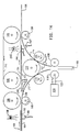
- Figure 14 shows a cross-section of the preferred embodiment of the present invention.
- the apparatus comprises an input tray 104.
- the input tray is coupled to receive a workpiece and provide it into the apparatus.
- a coacting pair of brushes or rollers 108 and 110 is positioned at the end of the input tray 104.
- An input arc member 246 is adjacent to and positioned to receive workpieces from the input tray 104.
- Coacting brushes or rollers 112 and 114 are positioned through an opening the input arc member 246.
- a slot 160 is positioned directly below the roller or brush 112.
- the coacting rollers and brushes 118 and 120 are positioned,near the top of the slot 160.
- the brush 118 is coup led to a pin 122 of the air cylinder 124. In this manner, the brush or roller 118 can be extended to contact the brush or roller 120.
- a second arc member 156 extends from the slot 160 away from the arc 246.
- the two arcs 246 and 156 and the walls of slot 160 form a shape somewhat similar to a Y.
- the coacting brushes 112 and 116 are positioned through an opening in the arc 156.
- the coacting brushes 126 and 128 are positioned at the upper end of the arc 156.
- the output tray 106 is adjacent to and positioned to receive workpieces from the arc 156.
- a horizontal tray 154 extends substantially across the top of the Y formed by arcs246, 156 and the walls of the slot 160 between the coacting brushes 108 and 110 to the coacting brushes 126 and 128. There is a gap between tray 154 and the coacting brushes 108 and 110 which gate 250 can bridge as shown in Figure 23.
- a roller 130 is positioned at the opposite end of the horizontal tray 154 from the roller 126. The rollers 130 and 126 are coupled to one another by the belt 132 and accordingly rotate uniformly.
- a light source 138 is positioned over the input tray 104 to illuminate a photo sensor 140 which is located within the input tray 104.
- a light source 242 illuminates a photo cell 244 which is positioned near the downstream end of tray 154 and a photo cell 264 which is positioned near the top of the arc 156.
- the light sources 242 and 138 may in fact be a single light source.
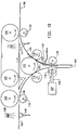
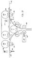
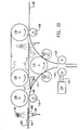
- Figures 14 through 22 shows the sequence of events which occur to flip a piece of fabric or other workpiece over within the apparatus of the preferred embodiment of the present invention.
- Figure 14 shows a piece of fabric having a top surface 100 and bottom surface 102 and moving to the right along input tray 104.
- the piece of fabric is covering photo cell 140 thereby preventing the light from striking input tray 104.
- the input tray 104 can be, for example, a conveyor or other means for causing the fabric to traverse into the machine.
- Figure 15 shows that the fabric has been gripped by the coacting rollers 108 and 110; the roller 108 is rotating in a counterclockwise direction and roller 110 is rotating in a clockwise direction. The two rollers actually touch thereby gripping the fabric and propelling it into the apparatus. Due to the force of gravity, the piece of fabric will follow the input arc 246 downward.
- roller 112 is shown to rotate in a counterclockwise and roller 114 is shown to rotate in a clockwise direction.
- the coacting rollers 112 and 114 touch to pull and propel the fabric downward into the slot 160.
- the piece of fabric has passed into the slot 160 and no longer covers the photo cell 140 which instructs the air cylinder 124 to extend its pin 122 to push the roller 118 into contact with roller 120 in Figure 17. At this point in the operation, neither roller 118 nor roller 120 are rotating but, by touching together they prevent further motion of the fabric in a downward direction into the slot 160.
- the workpiece has flipped from the input arc 152 to exit the arc 156 due to the rotational direction of roller 112 in Figure 18. What was the trailing end of the workpiece is now the leading end of the workpiece and is positioned between the coacting rollers 112 and 116.
- the photo cell 162 is blocked from receiving light by the piece of fabric which indicates that the piece of fabric has flipped and is in the exit cycle and instructs the rollers 118 and 120 to rotate.
- the photo cell 162 can receive light from light source 138 or 242. In the alternative, a third light source may be positioned to illuminate the photo cell 162.
- Figure 19 shows that the coacting rollers 118 and 120 have begun to rotate; the roller 118 is rotating in a counterclockwise direction and the roller 120 is rotating in a clockwise direction.
- the coacting rollers 112 and 116 continue to rotate counterclockwise and clockwise respectively.
- the combination of the rotation of these four rollers 112, 116, 118 and 120 acts to pull the fabric out of the slot 160.
- the top surface 100 of the fabric workpiece is against the exit arc 156.
- the fabric is still blocking light from impinging on the photo cell 162.
- the fabric has passed beyond photo sensor 162 in Figure 20 instructing the coacting rollers 118 and 120 to stop rotating and the air cylinder 124 and pin 122 to retract the roller 118 in preparation for the next workpiece. Also, the fabric blocks light from impinging on the photo cell 264 indicating that the workpiece is ready to exit the apparatus.
- Figure 21 shows that the rotation of the coacting rollers 126 and 128 operates to draw the workpiece out of the apparatus onto the output tray 106.
- the output tray 106 is preferably a conveyor.
- Figure 22 shows the workpiece leaving the apparatus of the present invention.
- the photo sensor 264 is now uncovered to indicate that the workpiece has left the apparatus.
- Figures 23 through 26 show the operation of the apparatus where the workpiece does not get flipped over.
- the workpiece enters the apparatus on input tray 104 as before except that the fabric is inverted from that shown in Figure 14, i.e., the top of the workpiece 100 is on the bottom and the bottom of the workpiece 102 is on the top.
- the control mechanism for the gate 250 is activated moving the gate to its second non-flip position 251.
- Figure 24 shows that the coacting rollers 108 and 110 have gripped the workpiece and propelled it into the apparatus on the arc 246 and onto the gate which is in the non-flip position 251.
- the workpiece is driven into contact with the belt 132 and is driven across the horizontal tray 154 by the belt 132 in Figure 25.
- the belt 132 is driven by the rollers 126 and 130. As the workpiece approaches the downstream end of the tray 154 it blocks the photo cell 244 indicating that the workpiece is ready to exit the apparatus.
- Figure 26 shows the workpiece being propelled by the coacting rollers 126 and 128 onto output tray 106.
- Figure 22 also shows the last figure in this sequence. After the workpiece clears the photo sensor 244, the gate returns to the flip position 250 in preparation for the next workpiece.
- the two photo cells 244 and 264 act cooperatively to prevent collisions of flipped and non-flipped workpieces.
- the electronic control apparatus 36 receives signals from each of the photo cells 140, 162, 244 and 264. Because the flipped and non-flipped workpieces travel different distances it is important to control when they are allowed to leave the apparatus.
- the rollers 112, 114, 116, 118 and 120 are driven faster than the remaining rollers but precise timing is difficult to achieve with such mechanical systems.
- rollers 108 and 110 can be clutched to high speed during a flip cycle.
- a flipped workpiece is stopped as it blocks the photo cell 264 because that cell instructs the rollers 112, 116, 118 and 120 to stop until downstream equipment needs that workpiece.
- a non-flipped workpiece can traverse through the apparatus at the same speed required by downstream equipment. Further, the flipped workpiece cannot begin moving again until the photo cell 244 tells the electronic control 36 that the non-flipped workpiece is clear.
Landscapes
- Engineering & Computer Science (AREA)
- Textile Engineering (AREA)
- Mechanical Engineering (AREA)
- Treatment Of Fiber Materials (AREA)
- Forging (AREA)
- Forklifts And Lifting Vehicles (AREA)
- Separation, Sorting, Adjustment, Or Bending Of Sheets To Be Conveyed (AREA)
- Registering, Tensioning, Guiding Webs, And Rollers Therefor (AREA)
- Attitude Control For Articles On Conveyors (AREA)
- Registering Or Overturning Sheets (AREA)
Applications Claiming Priority (2)
| Application Number | Priority Date | Filing Date | Title |
|---|---|---|---|
| US570428 | 1990-08-21 | ||
| US07/570,428 US5106075A (en) | 1989-04-04 | 1990-08-21 | Fabric turner |
Publications (2)
| Publication Number | Publication Date |
|---|---|
| EP0472410A1 true EP0472410A1 (de) | 1992-02-26 |
| EP0472410B1 EP0472410B1 (de) | 1995-10-25 |
Family
ID=24279617
Family Applications (1)
| Application Number | Title | Priority Date | Filing Date |
|---|---|---|---|
| EP91307671A Expired - Lifetime EP0472410B1 (de) | 1990-08-21 | 1991-08-20 | Gewebewendevorrichtung |
Country Status (6)
| Country | Link |
|---|---|
| US (1) | US5106075A (de) |
| EP (1) | EP0472410B1 (de) |
| JP (1) | JP2948379B2 (de) |
| AT (1) | ATE129479T1 (de) |
| CA (1) | CA2049445C (de) |
| DE (1) | DE69114081T2 (de) |
Families Citing this family (22)
| Publication number | Priority date | Publication date | Assignee | Title |
|---|---|---|---|---|
| US5535997A (en) * | 1993-06-10 | 1996-07-16 | Levi Strauss & Co. | Fabric piece automatic feeder with suction cup picker and twisted-belt flipper |
| US5382013A (en) * | 1993-10-12 | 1995-01-17 | Xerox Corporation | Clutch driven inverter shaft |
| US5590872A (en) * | 1994-03-31 | 1997-01-07 | Minolta Co., Ltd. | Sheet reversing apparatus for a copying machine |
| US5449164A (en) * | 1994-08-29 | 1995-09-12 | Xerox Corporation | Sheet inverter apparatus |
| US5630496A (en) * | 1995-03-30 | 1997-05-20 | Machine Builders And Design | Apparatus and method for flipping and positioning articles |
| US5967505A (en) * | 1997-03-21 | 1999-10-19 | Levi Strauss & Co. | Automatic feeder and inverter for fabric workpieces |
| US6098782A (en) * | 1998-04-24 | 2000-08-08 | Campbell-Hardage, Inc. | Rotary manipulator for conveyor goods |
| EP1084974A3 (de) * | 1999-09-17 | 2003-01-08 | Omron Corporation | Wendevorrichtung für Bögen |
| US6419222B1 (en) * | 2000-12-12 | 2002-07-16 | Xerox Corporation | Sheet inverting apparatus and method |
| JP4602196B2 (ja) * | 2005-08-16 | 2010-12-22 | 株式会社東芝 | 紙葉類処理装置 |
| WO2007020667A1 (en) * | 2005-08-19 | 2007-02-22 | Golden Lady Company S.P.A. | Device and method for handling tubular knitted articles, such as stockings and socks or the like |
| DE102005040652A1 (de) * | 2005-08-26 | 2007-03-01 | Eastman Kodak Company | Vorrichtung zur Ablage von Bögen für eine Bögen grafisch verarbeitende Maschine |
| US7963518B2 (en) * | 2006-01-13 | 2011-06-21 | Xerox Corporation | Printing system inverter apparatus and method |
| WO2007083330A1 (en) * | 2006-01-19 | 2007-07-26 | Santoni S.P.A. | Automatic device to insert stockings in knitted-seaming machines |
| US7360636B2 (en) * | 2006-04-14 | 2008-04-22 | Dominic Theriault | Alternate package flip-over device |
| US20100272553A1 (en) * | 2009-04-22 | 2010-10-28 | Aschenbeck David P | Method And Apparatus For Handling Shingles |
| CN101987700B (zh) * | 2009-07-31 | 2013-06-05 | 山东新北洋信息技术股份有限公司 | 记录介质翻转机构及使用该机构的记录介质处理装置 |
| US8280263B2 (en) * | 2011-01-31 | 2012-10-02 | Xerox Corporation | Multi-feed detection and control system |
| JP5832198B2 (ja) * | 2011-08-19 | 2015-12-16 | キヤノン株式会社 | シート圧縮装置及び画像形成装置 |
| CN104085716A (zh) * | 2014-06-13 | 2014-10-08 | 浙江兰良实业有限公司 | 一种卷纸机的检验装置 |
| KR101712011B1 (ko) * | 2016-08-05 | 2017-03-09 | 주식회사 우성섬유 | 코팅장갑 제조장치 |
| CN109625874B (zh) * | 2018-12-24 | 2024-07-19 | 广州达意隆包装机械股份有限公司 | 一种柔性物品翻转输送装置 |
Citations (5)
| Publication number | Priority date | Publication date | Assignee | Title |
|---|---|---|---|---|
| US4054285A (en) * | 1976-03-08 | 1977-10-18 | Xerox Corporation | Apparatus for registering and inverting sheets |
| EP0047181A2 (de) * | 1980-09-02 | 1982-03-10 | Xerox Corporation | Substrat-Umkehrvorrichtung |
| US4699367A (en) * | 1986-02-24 | 1987-10-13 | Eastman Kodak Company | Sheet turnover mechanism |
| CH668054A5 (en) * | 1985-08-28 | 1988-11-30 | Kurt Ruenzi | Mechanism for turning over sheet of paper - consists of group of three rollers and associated guide plates |
| EP0391548A2 (de) * | 1989-04-04 | 1990-10-10 | LEVI STRAUSS & CO. | Wendevorrichtung für Gewebe |
Family Cites Families (12)
| Publication number | Priority date | Publication date | Assignee | Title |
|---|---|---|---|---|
| US2754953A (en) * | 1953-04-09 | 1956-07-17 | Firestone Tire & Rubber Co | Sheet material handling device |
| DE2438811A1 (de) * | 1974-08-13 | 1976-02-26 | Rudolf Grenzebach | Verfahren und vorrichtung zum wenden und paarweisen aufeinanderlegen von platten |
| US4078789A (en) * | 1977-01-21 | 1978-03-14 | Kittredge Lloyd G | Document inverter |
| US4673176A (en) * | 1980-10-02 | 1987-06-16 | Xerox Corporation | Soft nip damping inverter |
| US4359217A (en) * | 1980-09-02 | 1982-11-16 | Xerox Corporation | Inverter with proportional force paper drive |
| US4346880A (en) * | 1980-10-02 | 1982-08-31 | Xerox Corporation | Apparatus for inverting substrates |
| JPS5775392A (en) * | 1980-10-29 | 1982-05-11 | Hitachi Ltd | Front and back aligning device for sheets |
| JPS59151998A (ja) * | 1982-12-22 | 1984-08-30 | ゼンキングヴエルク・ゲゼルシヤフト・ミツト・ベシユレンクテル・ハフツング・ウント・コンパニ− | 洗濯物の塊を脱水するためのピストン式プレス |
| JPS6198757U (de) * | 1984-12-03 | 1986-06-24 | ||
| JPS62290668A (ja) * | 1986-06-06 | 1987-12-17 | Minolta Camera Co Ltd | シ−ト搬送装置 |
| JPS6443062U (de) * | 1987-09-07 | 1989-03-15 | ||
| US4799613A (en) * | 1987-11-09 | 1989-01-24 | Russell Corporation | Method and apparatus for sensing the preferred side of garment portions |
-
1990
- 1990-08-21 US US07/570,428 patent/US5106075A/en not_active Expired - Lifetime
-
1991
- 1991-08-20 AT AT91307671T patent/ATE129479T1/de active
- 1991-08-20 DE DE69114081T patent/DE69114081T2/de not_active Expired - Fee Related
- 1991-08-20 CA CA002049445A patent/CA2049445C/en not_active Expired - Fee Related
- 1991-08-20 EP EP91307671A patent/EP0472410B1/de not_active Expired - Lifetime
- 1991-08-21 JP JP3293970A patent/JP2948379B2/ja not_active Expired - Fee Related
Patent Citations (5)
| Publication number | Priority date | Publication date | Assignee | Title |
|---|---|---|---|---|
| US4054285A (en) * | 1976-03-08 | 1977-10-18 | Xerox Corporation | Apparatus for registering and inverting sheets |
| EP0047181A2 (de) * | 1980-09-02 | 1982-03-10 | Xerox Corporation | Substrat-Umkehrvorrichtung |
| CH668054A5 (en) * | 1985-08-28 | 1988-11-30 | Kurt Ruenzi | Mechanism for turning over sheet of paper - consists of group of three rollers and associated guide plates |
| US4699367A (en) * | 1986-02-24 | 1987-10-13 | Eastman Kodak Company | Sheet turnover mechanism |
| EP0391548A2 (de) * | 1989-04-04 | 1990-10-10 | LEVI STRAUSS & CO. | Wendevorrichtung für Gewebe |
Also Published As
| Publication number | Publication date |
|---|---|
| DE69114081T2 (de) | 1996-05-09 |
| ATE129479T1 (de) | 1995-11-15 |
| JPH05124760A (ja) | 1993-05-21 |
| EP0472410B1 (de) | 1995-10-25 |
| CA2049445A1 (en) | 1992-02-22 |
| CA2049445C (en) | 1997-02-11 |
| US5106075A (en) | 1992-04-21 |
| JP2948379B2 (ja) | 1999-09-13 |
| DE69114081D1 (de) | 1995-11-30 |
Similar Documents
| Publication | Publication Date | Title |
|---|---|---|
| US5106075A (en) | Fabric turner | |
| US3988017A (en) | Workpiece feeding device | |
| US3593624A (en) | Automatic stacking machine | |
| US4968021A (en) | Fabric turner | |
| SE419209B (sv) | Anordning for uppdelning av en kontinuerlig strom av arkformiga foremal i enskilda sektioner | |
| JPS59182156A (ja) | 紙葉類回収装置 | |
| US4565363A (en) | Apparatus for accurately spacing a sequence of shingled paper sheet products on a conveyor | |
| EP1972583B1 (de) | Hochgeschwindigkeitsvorrichtung zum Stapeln von geschuppten Bögen | |
| CA1090737A (en) | Flat mail sorter and loader | |
| ATE75207T1 (de) | Vorrichtung zum vereinzeln gestapelter papierbogen. | |
| US4436301A (en) | Document restack transport | |
| JP2008169044A (ja) | 順次重ねられたシートのスタックを整列するための装置と方法 | |
| US4416450A (en) | Letter conveyor switch drive | |
| US4161244A (en) | Mail buffer feeder system | |
| US3266796A (en) | Document handling apparatus | |
| US4735409A (en) | Sheet feeders | |
| US3602495A (en) | Device for the removal of sheets,inserts or the like released from a roller frame | |
| EP0085646B1 (de) | Vorrichtung zum Zählen und zum Stapeln von Pappdeckeln | |
| EP0459272A1 (de) | Synchronisierungsvorrichtung zum periodischen Zuführen von festen Gegenständen an einen zyklisch betätigten Taschenförderer oder an einen anderen Teil einer Maschine | |
| CN118907812B (zh) | 工件正反面筛选工装、工件筛选的上料装置及上料方法 | |
| US9567185B2 (en) | Sheet folding device | |
| JPH0432414A (ja) | 物品仕分け装置 | |
| JP2564553B2 (ja) | 紙葉類のスタッカ機構 | |
| JPH05105251A (ja) | 紙片供給装置 | |
| US4123049A (en) | Printing plate transfer apparatus |
Legal Events
| Date | Code | Title | Description |
|---|---|---|---|
| PUAI | Public reference made under article 153(3) epc to a published international application that has entered the european phase |
Free format text: ORIGINAL CODE: 0009012 |
|
| AK | Designated contracting states |
Kind code of ref document: A1 Designated state(s): AT BE CH DE DK ES FR GB GR IT LI LU NL SE |
|
| 17P | Request for examination filed |
Effective date: 19920803 |
|
| 17Q | First examination report despatched |
Effective date: 19931116 |
|
| GRAA | (expected) grant |
Free format text: ORIGINAL CODE: 0009210 |
|
| AK | Designated contracting states |
Kind code of ref document: B1 Designated state(s): AT BE CH DE DK ES FR GB GR IT LI LU NL SE |
|
| PG25 | Lapsed in a contracting state [announced via postgrant information from national office to epo] |
Ref country code: NL Free format text: LAPSE BECAUSE OF FAILURE TO SUBMIT A TRANSLATION OF THE DESCRIPTION OR TO PAY THE FEE WITHIN THE PRESCRIBED TIME-LIMIT Effective date: 19951025 Ref country code: LI Effective date: 19951025 Ref country code: GR Free format text: LAPSE BECAUSE OF FAILURE TO SUBMIT A TRANSLATION OF THE DESCRIPTION OR TO PAY THE FEE WITHIN THE PRESCRIBED TIME-LIMIT Effective date: 19951025 Ref country code: ES Free format text: THE PATENT HAS BEEN ANNULLED BY A DECISION OF A NATIONAL AUTHORITY Effective date: 19951025 Ref country code: DK Effective date: 19951025 Ref country code: CH Effective date: 19951025 Ref country code: AT Effective date: 19951025 |
|
| REF | Corresponds to: |
Ref document number: 129479 Country of ref document: AT Date of ref document: 19951115 Kind code of ref document: T |
|
| ET | Fr: translation filed | ||
| REF | Corresponds to: |
Ref document number: 69114081 Country of ref document: DE Date of ref document: 19951130 |
|
| ITF | It: translation for a ep patent filed | ||
| PG25 | Lapsed in a contracting state [announced via postgrant information from national office to epo] |
Ref country code: SE Effective date: 19960125 |
|
| NLV1 | Nl: lapsed or annulled due to failure to fulfill the requirements of art. 29p and 29m of the patents act | ||
| REG | Reference to a national code |
Ref country code: CH Ref legal event code: PL |
|
| PLBE | No opposition filed within time limit |
Free format text: ORIGINAL CODE: 0009261 |
|
| STAA | Information on the status of an ep patent application or granted ep patent |
Free format text: STATUS: NO OPPOSITION FILED WITHIN TIME LIMIT |
|
| PG25 | Lapsed in a contracting state [announced via postgrant information from national office to epo] |
Ref country code: LU Free format text: LAPSE BECAUSE OF NON-PAYMENT OF DUE FEES Effective date: 19960831 |
|
| 26N | No opposition filed | ||
| REG | Reference to a national code |
Ref country code: GB Ref legal event code: 732E |
|
| REG | Reference to a national code |
Ref country code: GB Ref legal event code: IF02 |
|
| REG | Reference to a national code |
Ref country code: FR Ref legal event code: GC |
|
| REG | Reference to a national code |
Ref country code: GB Ref legal event code: 732E |
|
| PGFP | Annual fee paid to national office [announced via postgrant information from national office to epo] |
Ref country code: FR Payment date: 20040810 Year of fee payment: 14 |
|
| PGFP | Annual fee paid to national office [announced via postgrant information from national office to epo] |
Ref country code: GB Payment date: 20040818 Year of fee payment: 14 |
|
| PGFP | Annual fee paid to national office [announced via postgrant information from national office to epo] |
Ref country code: DE Payment date: 20040902 Year of fee payment: 14 |
|
| REG | Reference to a national code |
Ref country code: FR Ref legal event code: DG |
|
| PGFP | Annual fee paid to national office [announced via postgrant information from national office to epo] |
Ref country code: BE Payment date: 20041020 Year of fee payment: 14 |
|
| PG25 | Lapsed in a contracting state [announced via postgrant information from national office to epo] |
Ref country code: IT Free format text: LAPSE BECAUSE OF NON-PAYMENT OF DUE FEES;WARNING: LAPSES OF ITALIAN PATENTS WITH EFFECTIVE DATE BEFORE 2007 MAY HAVE OCCURRED AT ANY TIME BEFORE 2007. THE CORRECT EFFECTIVE DATE MAY BE DIFFERENT FROM THE ONE RECORDED. Effective date: 20050820 Ref country code: GB Free format text: LAPSE BECAUSE OF NON-PAYMENT OF DUE FEES Effective date: 20050820 |
|
| PG25 | Lapsed in a contracting state [announced via postgrant information from national office to epo] |
Ref country code: BE Free format text: LAPSE BECAUSE OF NON-PAYMENT OF DUE FEES Effective date: 20050831 |
|
| PG25 | Lapsed in a contracting state [announced via postgrant information from national office to epo] |
Ref country code: DE Free format text: LAPSE BECAUSE OF NON-PAYMENT OF DUE FEES Effective date: 20060301 |
|
| GBPC | Gb: european patent ceased through non-payment of renewal fee |
Effective date: 20050820 |
|
| PG25 | Lapsed in a contracting state [announced via postgrant information from national office to epo] |
Ref country code: FR Free format text: LAPSE BECAUSE OF NON-PAYMENT OF DUE FEES Effective date: 20060428 |
|
| REG | Reference to a national code |
Ref country code: FR Ref legal event code: ST Effective date: 20060428 |
|
| BERE | Be: lapsed |
Owner name: *LEVI STRAUSS & CO. Effective date: 20050831 |