EP0472298B1 - Bierfass - Google Patents
Bierfass Download PDFInfo
- Publication number
- EP0472298B1 EP0472298B1 EP91306858A EP91306858A EP0472298B1 EP 0472298 B1 EP0472298 B1 EP 0472298B1 EP 91306858 A EP91306858 A EP 91306858A EP 91306858 A EP91306858 A EP 91306858A EP 0472298 B1 EP0472298 B1 EP 0472298B1
- Authority
- EP
- European Patent Office
- Prior art keywords
- keg
- face
- cooling
- inner cylinder
- liquid
- Prior art date
- Legal status (The legal status is an assumption and is not a legal conclusion. Google has not performed a legal analysis and makes no representation as to the accuracy of the status listed.)
- Expired - Lifetime
Links
- 235000013405 beer Nutrition 0.000 title abstract description 79
- 238000001816 cooling Methods 0.000 claims abstract description 33
- 239000007788 liquid Substances 0.000 claims description 30
- 230000000717 retained effect Effects 0.000 claims description 6
- 239000002826 coolant Substances 0.000 claims description 3
- 239000011810 insulating material Substances 0.000 claims 2
- 238000003466 welding Methods 0.000 description 6
- CURLTUGMZLYLDI-UHFFFAOYSA-N Carbon dioxide Chemical compound O=C=O CURLTUGMZLYLDI-UHFFFAOYSA-N 0.000 description 5
- XLYOFNOQVPJJNP-UHFFFAOYSA-N water Substances O XLYOFNOQVPJJNP-UHFFFAOYSA-N 0.000 description 5
- 229910002092 carbon dioxide Inorganic materials 0.000 description 2
- 239000001569 carbon dioxide Substances 0.000 description 2
- 239000002184 metal Substances 0.000 description 2
- OKTJSMMVPCPJKN-UHFFFAOYSA-N Carbon Chemical compound [C] OKTJSMMVPCPJKN-UHFFFAOYSA-N 0.000 description 1
- 229910052799 carbon Inorganic materials 0.000 description 1
- 235000011089 carbon dioxide Nutrition 0.000 description 1
- 239000003795 chemical substances by application Substances 0.000 description 1
- 238000010276 construction Methods 0.000 description 1
- 239000000498 cooling water Substances 0.000 description 1
- 238000004519 manufacturing process Methods 0.000 description 1
- 230000002441 reversible effect Effects 0.000 description 1
- 238000007789 sealing Methods 0.000 description 1
- 229910001220 stainless steel Inorganic materials 0.000 description 1
- 239000010935 stainless steel Substances 0.000 description 1
- 238000005406 washing Methods 0.000 description 1
Images


Classifications
-
- B—PERFORMING OPERATIONS; TRANSPORTING
- B65—CONVEYING; PACKING; STORING; HANDLING THIN OR FILAMENTARY MATERIAL
- B65D—CONTAINERS FOR STORAGE OR TRANSPORT OF ARTICLES OR MATERIALS, e.g. BAGS, BARRELS, BOTTLES, BOXES, CANS, CARTONS, CRATES, DRUMS, JARS, TANKS, HOPPERS, FORWARDING CONTAINERS; ACCESSORIES, CLOSURES, OR FITTINGS THEREFOR; PACKAGING ELEMENTS; PACKAGES
- B65D15/00—Containers having bodies formed by interconnecting or uniting two or more rigid, or substantially rigid, sections made of different materials
-
- B—PERFORMING OPERATIONS; TRANSPORTING
- B65—CONVEYING; PACKING; STORING; HANDLING THIN OR FILAMENTARY MATERIAL
- B65D—CONTAINERS FOR STORAGE OR TRANSPORT OF ARTICLES OR MATERIALS, e.g. BAGS, BARRELS, BOTTLES, BOXES, CANS, CARTONS, CRATES, DRUMS, JARS, TANKS, HOPPERS, FORWARDING CONTAINERS; ACCESSORIES, CLOSURES, OR FITTINGS THEREFOR; PACKAGING ELEMENTS; PACKAGES
- B65D7/00—Containers having bodies formed by interconnecting or uniting two or more rigid, or substantially rigid, components made wholly or mainly of metal
- B65D7/02—Containers having bodies formed by interconnecting or uniting two or more rigid, or substantially rigid, components made wholly or mainly of metal characterised by shape
- B65D7/04—Containers having bodies formed by interconnecting or uniting two or more rigid, or substantially rigid, components made wholly or mainly of metal characterised by shape of curved cross-section, e.g. cans of circular or elliptical cross-section
- B65D7/045—Casks, barrels, or drums in their entirety, e.g. beer barrels, i.e. presenting most of the following features like rolling beads, double walls, reinforcing and supporting beads for end walls
Definitions
- the present invention relates to a keg for a liquid, in particular for draft beer, which is provided with means to facilitate cooling of the liquid retained in the keg and to keep the temperature of the cooled liquid in the keg.
- Draft beer is generally filled in a metal container called a beer barrel for transportation and, at the time of sale, it is taken into a jug or the like directly from the beer barrel together with pressurized carbon dioxide.
- draft beer is filled in a metal beer barrel at relatively low temperature.
- the temperature rises to atmospheric temperature during the transportation and storage of the draft beer.
- the draft beer is momentarily cooled by a coil cooler at the time of sale.
- a primary aim of the present invention is to provide a keg for beer (or other liquid) which can effectively keep cool draft beer retained in the keg, while shipping of draft beer to a store and storage of draft beer.
- Another aim of the invention is to provide a keg which can be forcibly cooled from outside when required.
- the present invention provides a keg for a liquid such as draft beer to facilitate cooling of the liquid retained in the keg and to keep the temperature of the cooled liquid in the keg, comprising: a keg body for retaining the liquid therein and having an upper face, a lower face, a side face and a mouth piece for providing the liquid into the keg body and ejecting the liquid therefrom, said keg body being formed of a keg inner cylinder for constituting a container for the liquid and a keg outer cylinder for substantially covering the keg inner cylinder except one of the upper and lower faces of the keg body, said keg inner and outer cylinders being laminated together to form a space and air being removed from the space to form a vacuum adiabatic layer therebetween; and a cooling face formed on said one of the upper and lower faces of the keg body where the inner cylinder is not covered so that the liquid inside the inner cylinder can be cooled through the cooling face and the temperature of the liquid inside the inner
- the keg of the invention is basically used to keep cool draft beer retained inside the keg.
- the keg is formed of a keg body in the form of a container for retaining draft beer or other liquid therein, a cooling face formed on a part of the keg body, and an adiabatic layer for covering an outer surface of the keg body.
- the liquid contained inside the keg body is cooled through the cooling face, and the adiabatic layer insulates heat from outside to keep the liquid inside the keg body cool.
- the container also includes a mouth piece for providing the liquid into the keg body and ejecting the liquid therefrom.
- the cooling face is formed on an appropriate portion, that is an upper face or a lower face.
- the adiabatic layer may be formed of double plates having a space therein, from which air is removed to provide vacuum condition between the two plates.
- the keg of the present invention has high capability of keeping beer cool due to the adiabatic structure.
- the adiabatic structure is not applied to the cooling face.
- Draft beer in the keg is kept cool by mounting an adiabatic mat, a cooling agent such as dry ice, ice, etc. or a cooling device on the cooling face.
- the beer keg is housed in a large refrigerator so that the draft beer in the container is cooled by touching the cooling face.
- the beer keg according to the present invention maintains draft beer at lower temperature during the time from shipping of draft beer to sale at the store, so that it can present draft beer to a customer without losing the inherent taste and aroma thereof. Moreover, the present invention does not require cooling by the conventionally used coil cooler, so that it can be treated sanitarily.
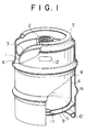
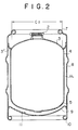
- a beer keg according to a first embodiment of the invention is shown.
- the beer keg comprises a combination of a keg inner cylinder 1 and a keg outer cylinder 6.
- the keg inner cylinder 1 is a container made of thin stainless steel plate, and having a mouth piece 2 and a bottom.
- the keg inner cylinder 1 is prepared by welding an inner cylinder shell 4 with an inner cylinder upper plate 3 and an inner cylinder lower plate 5.
- the inner cylinder shell 4 is in a cylindrical form and is integrally sealed, at its upper and lower edges with the inner cylinder plate 3 and the inner cylinder plate 5, respectively, by TIG welding.
- the mouth piece 2 is mounted on the center of the inner cylinder plate 3.
- a down tube 13 shown in Fig. 3 is inserted into the keg inner cylinder 1 through the mouth piece 2.
- the down tube 13 is a tube for providing draft beer into the inside of the keg inner cylinder 1 and also ejecting draft beer from the cylinder 1.
- the down tube 13 has a carbon dioxide-valve (not shown) and a beer valve (not shown) and is screwed in the mouth piece to be fixed.
- the inner cylinder upper plate 3 which covers the upper portion of the keg inner cylinder 1 is welded to the the keg inner cylinder 1 in such a manner that a certain length of the upper plate 3 projects outwardly over the outer diameter of the keg inner cylinder 1.
- the keg outer cylinder 6 covers the keg inner cylinder 1 and is formed of an outer cylinder shell 8 and an outer cylinder lower plate 9.
- the outer cylinder shell 8 has an upper grip 7 at its upper opening edge and a keg leg 10 at its lower opening edge, respectively. Both upper and lower edges are bent inwardly. The diameter of the upper edge is slightly smaller than that of the lower edge, but the upper and lower portions of the outer cylinder shell 8 may be reversible upside down.
- the upper edge acts as the upper grip 7 and the lower edge operates as the keg leg 10.
- the upper edge acts as the keg leg 10 and the lower edge acts as the upper grip 7.
- a hole 12 is provided on the upper portion of the outer cylinder shell 8 so as to use it as a grip.
- the above-mentioned keg inner cylinder 1 is housed in the keg outer cylinder 6 such that the projecting edge 3' of the inner cylinder upper plate 3 which covers the upper opening of the keg inner cylinder 1 is airtightly connected to the internal circumferential face of the outer cylinder shell 8 by means of TIG welding.
- the outer cylinder lower plate 9 is airtightly welded to the inner circumferential face of the outer cylinder shell 8 by TIG welding to cover the bottom of the keg inner cylinder 1, so that the space defined between the keg inner cylinder 1 and the outer cylinder shell 8 is airtightly sealed.
- the order of welding is important.
- the outer cylinder lower plate 9 is provided with a nozzle 11 having a valve. After the valve is opened and the nozzle 11 is connected to a vacuum pump (not shown) air in the space defined between the barrel inner cylinder 1 and the outer cylinder shell 8 is removed. Then, the valve is closed to form vacuum adiabatic layer V L within said space. Thus, the beer keg becomes a vacuum adiabatic container except for the inner cylinder upper plate 3.
- a beer keg incorporated with the down tube 13 is automatically washed and draft beer is automatically filled in the beer keg.
- the beer keg of the present invention is automatically washed and filled with draft beer by using the above-mentioned line.
- the beer keg filled with draft beer is stored in a refrigerator for shipping to forcibly cool beer in the keg through the face Cz.
- the upper face of the inner cylinder upper plate 3 of the beer keg is covered with an adiabatic mat 14 to keep low temperature.
- the beer keg is kept in a proper standing posture, so that temperature of draft beer filled in the beer keg inner cylinder 1 does not substantially rise due to the fact that draft beer is heat-insulated by the vacuum layer between the keg inner cylinder 1 and the outer cylinder shell 8.
- beer is kept cool in a refrigerator in an inverted posture or horizontal posture. Draft beer is cooled through the face Cz of the inner cylinder upper plate 3, so that the draft beer can be effectively forcibly cooled.
- the upper end hole of the outer-cylinder shell 8 is reduced in diameter to be smaller than the lower end hole, but either one of the upper and lower edges of the outer cylinder shell 8 becomes a grip or keg leg, so that the beer keg can be placed without distinguishing upper and lower portions.
- beer is supplied in a conventional manner to a jug or the like through the down tube 13 while carbon dioxide is injected with pressure, wherein the beer keg is vertically positioned to locate the mouth piece upwardly.
- a cooling agent a is inserted between the adiabatic mat 14 and the inner cylinder upper plate 3.
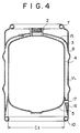
- FIG. 4 A second embodiment is shown in Fig. 4, wherein the inner cylinder lower plate 5 at the lower face of the keg inner cylinder 1 is used as a face Cz for cooling.
- the inner cylinder upper plate 3 is covered with an outer cylinder upper plate 15 connected to the outer cylinder shell 8 and the mouth piece 2 is fixed to the inner cylinder upper plate 3 through the outer cylinder upper plate 15.
- the lower edge of the keg outer cylinder 6 and the inner cylinder shell 4 are sealed by a sealing ring 16, so that a vacuum adiabatic layer V L is formed in a space surrounded by the keg outer cylinder 6.
- a reference numeral 17 is a water-extracting hole or an eye-hole which opens through the outer cylinder shell 8 and faces to the lower space of the inner cylinder lower plate 5.
- the water-extracting hole 17 is used such that when the container body is, for example, dipped in a cooling water tank to be kept cool, air in the lower space of the inner cylidner lower plate 5 is exhausted to enter cooled water into this space.
- the inner cylinder lower plate 5 when the beer keg is transported and stored, the inner cylinder lower plate 5 is inverted to orient upwardly and is forcibly cooled by a cool accumulating agent and so on as in the first embodiment. In use, the beer keg is returned to the proper standing posture and its lower portion is dipped within the cooling tank.
- Fig. 5 shows an embodiment of the beer keg in which a tank bottom plate 18 is installed on the inner circumferential face of the outer cylinder shell 8 so as to cover the inner cylinder lower plate 5 which becomes a cooling face Cz and a cooling tank 19 is pre-fabricated between the inner cylinder lower plate 5 and the keg bottom plate 18.
- the cooling tank 19 is provided with a water inlet pipe 20 and a water outlet pipe 21 to circulate cooled water in the cooling tank so as to allow the face Cz of the inner cylinder lower plate 5 to be forcibly cooled.
- draft beer can be kept cool at suitable temperature in case of necessity.
- the draft beer in the container can be kept cool as a whole by a convection phenomenon.
- the combination of the double cylinders such as inner and outer cylinders is not required and a keg body may be made by a combination of inner and outer cylinders in which the inside of the outer cylinder shell is sealed by an inner cylinder upper plate and an outer cylinder upper plate.
Landscapes
- Engineering & Computer Science (AREA)
- Mechanical Engineering (AREA)
- Packages (AREA)
- Devices For Dispensing Beverages (AREA)
- Distillation Of Fermentation Liquor, Processing Of Alcohols, Vinegar And Beer (AREA)
- Containers Having Bodies Formed In One Piece (AREA)
- Packging For Living Organisms, Food Or Medicinal Products That Are Sensitive To Environmental Conditiond (AREA)
Claims (9)
- Fäßchen für eine Flüssigkeit um das Kühlen der in dem Fäßchen enthaltenen Flüssigkeit zu erleichtern, und um die Temperatur der gekühlten Flüssigkeit in dem Fäßchen aufrechtzuerhalten, wobei dieses Fäßchen aufweist:
einen Fäßchenkörper zur Aufnahme der Flüssigkeit, mit einer oberen Fläche (3), einer unteren Fläche (5), einer Seitenfläche (4), und einem Mundstück (2), um die Flüssigkeit in den Fäßchenkörper einzufüllen und daraus auszustoßen, wobei dieser Fäßchenkörper gebildet wird von einem inneren Fäßchenzylinder (1), der einen Behälter für die Flüssigkeit darstellt, und einem äußeren Fäßchenzylinder (6), und der innere und der äußere Fäßchenzylinder zusammenlaminiert sind, um einen Zwischenraum zu bilden, und die Luft aus dem Zwischenraum entfernt wird. um eine adiabatische Vakuumschicht (VL) dazwischen zu bilden; dadurch gekennzeichnet, daß der äußere Fäßchenzylinder (6) den inneren Fäßchenzylinder (1) im wesentlichen bedeckt, und zwar mit Ausnahme der oberen oder unteren Fläche (3, 5) des Fäßchenkörpers, und daß auf der oberen oder unteren Fläche (3, 5) des Fäßchenkörpers eine Kühlfläche (Cz) gebildet ist, bei der der innere Zylinder (1) nicht bedeckt ist, so daß die Flüssigkeit in dem inneren Zylinder (1) über die Kühlfläche gekühlt werden kann, und die Temperatur der Flüssigkeit in dem inneren Zylinder durch die zwischen dem inneren und äußeren Zylinder definierte, adiabatische Schicht aufrechterhalten wird. - Fäßchen gemäß Anspruch 1, dadurch gekennzeichnet, daß die Kühlfläche (Cz) mit einer Kühlvorrichtung zum Kühlen des Fäßchenkörpers versehen ist.
- Fäßchen gemäß Anspruch 1 oder 2, dadurch gekennzeichnet, daß das Mundstück (2) an der Kühlfläche (Cz) des Fäßchenkörpers befestigt ist.
- Fäßchen gemäß Anspruch 1 oder 2, dadurch gekennzeichnet, daß das Mundstück (2) an der oberen Fläche (3) befestigt ist, und die Kühlfläche (Cz) auf der unteren Fläche (5) gebildet ist, so daß die Flüssigkeit über die untere Fläche des inneren Fäßchenzylinders (1) gekühlt wird.
- Fäßchen gemäß irgendeinem der Ansprüche 1 bis 3, dadurch gekennzeichnet, daß die Kühlfläche (Cz) auf der oberen Fläche (3) des Fäßchenkörpers gebildet ist.
- Fäßchen gemäß irgendeinem der Ansprüche 1 bis 3, dadurch gekennzeichnet, daß die Kühlfläche (Cz) auf der unteren Fläche (5) des Fäßchenkörpers gebildet ist.
- Fäßchen gemäß irgendeinem der Ansprüche 1 bis 6, dadurch gekennzeichnet, daß der äußere Fäßchenzylinder (6) einen oberen und einen unteren Rand hat, die einen Griff (7) bzw. einen Fäßchenfuß (10) aufweisen.
- Fäßchen gemäß irgendeinem der Ansprüche 1 bis 7, dadurch gekennzeichnet, daß es weiterhin ein isolierendes Material (14) aufweist, das an der Kühlfläche (Cz) befestigt wird, wenn das Fäßchen transportiert wird, so daß die Flüssigkeit in dem Fäßchen kühl gehalten wird.
- Fäßchen gemäß Anspruch 8, dadurch gekennzeichnet, daß es weiterhin ein Kühlmittel (a) aufweist, das zwischen der Kühlfläche (Cz) und dem isolierenden Material (14) angeordnet ist, so daß die Flüssigkeit in dem Fäßchen während des Transports kühl gehalten wird.
Applications Claiming Priority (6)
| Application Number | Priority Date | Filing Date | Title |
|---|---|---|---|
| JP199309/90 | 1990-07-30 | ||
| JP19930990A JP2905932B2 (ja) | 1990-07-30 | 1990-07-30 | 真空断熱式ビア樽 |
| JP9109/91 | 1991-02-01 | ||
| JP1991009109U JP2566090Y2 (ja) | 1991-02-01 | 1991-02-01 | 冷却槽付き真空断熱式ビア樽 |
| JP9110/91 | 1991-02-01 | ||
| JP1991009110U JP2566091Y2 (ja) | 1991-02-01 | 1991-02-01 | 生ビール用樽 |
Publications (2)
| Publication Number | Publication Date |
|---|---|
| EP0472298A1 EP0472298A1 (de) | 1992-02-26 |
| EP0472298B1 true EP0472298B1 (de) | 1995-09-13 |
Family
ID=27278330
Family Applications (1)
| Application Number | Title | Priority Date | Filing Date |
|---|---|---|---|
| EP91306858A Expired - Lifetime EP0472298B1 (de) | 1990-07-30 | 1991-07-26 | Bierfass |
Country Status (6)
| Country | Link |
|---|---|
| US (1) | US5165569A (de) |
| EP (1) | EP0472298B1 (de) |
| KR (1) | KR920002440A (de) |
| AT (1) | ATE127754T1 (de) |
| CS (1) | CS234891A3 (de) |
| DE (1) | DE69112962T2 (de) |
Families Citing this family (35)
| Publication number | Priority date | Publication date | Assignee | Title |
|---|---|---|---|---|
| DE4131899A1 (de) * | 1991-09-25 | 1993-04-01 | Rheinpfaelzische Emballagenfab | Stahlfass und verfahren zu seiner herstellung |
| US5287986A (en) * | 1993-02-11 | 1994-02-22 | Abell Corporation | Containment tank assembly |
| US5421478A (en) * | 1993-04-15 | 1995-06-06 | Lovato; Wilbur | Storage tank and baffle |
| JP2920060B2 (ja) * | 1994-02-03 | 1999-07-19 | 日本酸素株式会社 | 断熱容器とその製造方法 |
| US5638896A (en) * | 1994-02-03 | 1997-06-17 | Nippon Sanso Corporation | Cold-hot storage box with inert gas insulating jacket |
| US6474496B1 (en) | 2000-03-06 | 2002-11-05 | Snyder Industries, Inc. | Containment tank assembly |
| US6318581B1 (en) | 2000-03-06 | 2001-11-20 | Snyder Industries, Inc. | Discharge outlet for double wall containment tank assembly |
| US6925872B2 (en) | 2001-11-19 | 2005-08-09 | Anthony J. Hadala | Temperature-sensing device for determining the level of a fluid |
| WO2002068914A1 (en) * | 2001-02-23 | 2002-09-06 | Hadala, Anthony, J. | A temperature-sensing device for determining the level of a fluid |
| GB0209912D0 (en) * | 2002-05-01 | 2002-06-05 | Cypherco Ltd | Dispenser |
| DE20219927U1 (de) * | 2002-12-23 | 2003-03-06 | Warsteiner Brauerei Haus Cramer KG, 59581 Warstein | Getränkefass |
| EP1507125A3 (de) * | 2003-08-13 | 2008-02-27 | Cool-System Bev. GmbH | Behältnis mit wenigstens einer Vakuumkammer mit einer Zugangsöffnung, insbesondere Getränkebehältnis wie Bierfass oder dergleichen |
| US7302846B2 (en) * | 2004-03-12 | 2007-12-04 | Hadala Anthony J | Temperature-sensing device for determining the level of a fluid |
| CN101772461B (zh) * | 2007-08-09 | 2012-09-26 | 朝日啤酒株式会社 | 饮料用容器及其冷却系统 |
| US8967407B2 (en) * | 2009-07-27 | 2015-03-03 | Rehrig Pacific Company | Plastic beer keg |
| US9434505B2 (en) * | 2010-01-26 | 2016-09-06 | Rehrig Pacific Company | Plastic beer keg |
| DE202011050795U1 (de) * | 2011-07-22 | 2011-09-12 | Holger Blum | Behälter für flüssige Chemikalien |
| US9795242B2 (en) | 2013-02-14 | 2017-10-24 | Cirkul, Inc. | Additive delivery systems and containers |
| USD735436S1 (en) * | 2013-11-04 | 2015-07-28 | Deep Wood Brew Products, LLC | Mini-keg growler |
| USD752839S1 (en) * | 2013-11-04 | 2016-03-29 | Deep Wood Brew Products, LLC | Mini-keg growler neck without cap |
| US9428720B2 (en) | 2013-11-08 | 2016-08-30 | Deep Wood Brew Products, LLC | Mini-keg growler |
| DE102014207300B4 (de) * | 2014-04-16 | 2021-07-29 | Bayerische Motoren Werke Aktiengesellschaft | Verfahren zur Herstellung eines Tanks, insbesondere eines Kraftfahrzeugtanks |
| WO2015183752A1 (en) * | 2014-05-24 | 2015-12-03 | GrowlerWerks, INC. | Beverage dispenser and variable presure regulator cap assembly |
| CA2895614A1 (en) | 2014-06-23 | 2015-12-23 | Rehrig Pacific Company | Plastic beer keg |
| KR101597049B1 (ko) | 2014-10-24 | 2016-02-23 | 강성탁 | 생맥주통 |
| US10888826B2 (en) | 2014-11-21 | 2021-01-12 | Cirkul, Inc. | Adjustable additive cartridge systems and methods |
| JP6730298B2 (ja) | 2014-11-21 | 2020-07-29 | サークル, インコーポレイテッド.Cirkul, Inc. | 添加剤カートリッジ及び添加剤供給システム |
| USD799146S1 (en) * | 2016-01-15 | 2017-10-03 | Mark Fuller | Beverage container |
| USD794899S1 (en) * | 2016-05-25 | 2017-08-15 | MoreFlavor, Inc. | Keg |
| EP3478592A4 (de) * | 2016-06-29 | 2019-12-18 | Nesterenko, Ievgen | Wiederverwendbare edelstahlflasche zum transportieren und lagern von flüssigkeiten und verfahren zur herstellung davon |
| US11730173B2 (en) * | 2016-08-01 | 2023-08-22 | Toddy, Llc | Raised bottom cold brewer and method using same |
| US12017191B2 (en) | 2017-03-06 | 2024-06-25 | Cirkul, Inc. | Adjustable additive delivery systems and dispensing closure valves for the same |
| US10512358B1 (en) | 2018-10-10 | 2019-12-24 | LifeFuels, Inc. | Portable systems and methods for adjusting the composition of a beverage |
| AU2021308637A1 (en) * | 2020-07-15 | 2023-02-16 | Cirkul, Inc. | Portable carbonating dispensers |
| USD1096259S1 (en) | 2023-07-10 | 2025-10-07 | Simpler Beverage Solutions, Llc | Pump keg with adjustable tap dispenser |
Family Cites Families (13)
| Publication number | Priority date | Publication date | Assignee | Title |
|---|---|---|---|---|
| GB593216A (en) * | 1945-06-25 | 1947-10-10 | David William Nicholson | Improvements in or relating to liquid storage containers |
| US2214344A (en) * | 1935-10-24 | 1940-09-10 | John J Daly | Beverage barrel cooler |
| US2132722A (en) * | 1936-02-13 | 1938-10-11 | Pressed Steel Tank Company | Metal container |
| US2151856A (en) * | 1936-10-26 | 1939-03-28 | Edward F Lee | Cooling system for metal barrels |
| US2116795A (en) * | 1937-02-10 | 1938-05-10 | Edward F Lee | Double walled barrel |
| US2249051A (en) * | 1937-11-08 | 1941-07-15 | Herman E Schulse | Beverage container |
| US2343717A (en) * | 1940-11-06 | 1944-03-07 | Henry C Turnau | Beverage container |
| FR923129A (fr) * | 1946-01-17 | 1947-06-27 | Louvroil Montbard Aulnoye | Fût métallique à double paroi isotherme |
| GB686993A (en) * | 1949-10-11 | 1953-02-04 | Frederick John Trevallon Barne | Improvements in or relating to metal containers for fluids |
| GB1225625A (de) * | 1967-06-26 | 1971-03-17 | ||
| US4242884A (en) * | 1979-05-07 | 1981-01-06 | Kotschwar Rex R | Beverage cooler |
| US4573603A (en) * | 1985-06-03 | 1986-03-04 | Worthington Industries, Inc. | Fluid container |
| US4997124A (en) * | 1988-04-20 | 1991-03-05 | Zojirushi Corporation | Vacuum-insulated, double-walled metal structure and method for its production |
-
1991
- 1991-07-23 US US07/733,736 patent/US5165569A/en not_active Expired - Lifetime
- 1991-07-25 KR KR1019910012792A patent/KR920002440A/ko not_active Ceased
- 1991-07-26 EP EP91306858A patent/EP0472298B1/de not_active Expired - Lifetime
- 1991-07-26 CS CS912348A patent/CS234891A3/cs unknown
- 1991-07-26 DE DE69112962T patent/DE69112962T2/de not_active Expired - Fee Related
- 1991-07-26 AT AT91306858T patent/ATE127754T1/de not_active IP Right Cessation
Also Published As
| Publication number | Publication date |
|---|---|
| US5165569A (en) | 1992-11-24 |
| KR920002440A (ko) | 1992-02-28 |
| CS234891A3 (en) | 1992-03-18 |
| ATE127754T1 (de) | 1995-09-15 |
| EP0472298A1 (de) | 1992-02-26 |
| DE69112962D1 (de) | 1995-10-19 |
| DE69112962T2 (de) | 1996-04-11 |
Similar Documents
| Publication | Publication Date | Title |
|---|---|---|
| EP0472298B1 (de) | Bierfass | |
| US4745776A (en) | Single can cooler | |
| US5207076A (en) | Pitcher cooler | |
| US5974824A (en) | Container cooling jacket and pre-chill dispensing system therefor | |
| US4162029A (en) | Cooler chest/liquid dispenser combination | |
| US4071160A (en) | Insulated beer keg container | |
| US4699282A (en) | Beer display, keg cooler | |
| US4483157A (en) | Cold pack for beverage keg | |
| US2757517A (en) | Self-refrigerating container | |
| US3303667A (en) | Cryogenic apparatus | |
| JP2905932B2 (ja) | 真空断熱式ビア樽 | |
| JPH04311495A (ja) | ビール樽冷却装置 | |
| CN2330605Y (zh) | 一种密封保鲜桶 | |
| JPH04294742A (ja) | 飲料品充填容器 | |
| JP2566090Y2 (ja) | 冷却槽付き真空断熱式ビア樽 | |
| JPH0636454Y2 (ja) | 冷却器 | |
| JPS5911900Y2 (ja) | 生鮮物の低温輸送用容器 | |
| JP3057556U (ja) | 保冷材兼用凍結飲料 | |
| CN217478038U (zh) | 便携式保温箱 | |
| KR200249362Y1 (ko) | 패트병 음료용 보냉용기 | |
| JPS6120457Y2 (de) | ||
| JP2566091Y2 (ja) | 生ビール用樽 | |
| JPH11124187A (ja) | 断熱容器 | |
| JP3014815U (ja) | 缶入り飲料のジョッキ風保冷容器 | |
| BR202019022565Y1 (pt) | Aperfeiçoamento introduzido em chopeira para acondicionamento de barril de chopp |
Legal Events
| Date | Code | Title | Description |
|---|---|---|---|
| PUAI | Public reference made under article 153(3) epc to a published international application that has entered the european phase |
Free format text: ORIGINAL CODE: 0009012 |
|
| AK | Designated contracting states |
Kind code of ref document: A1 Designated state(s): AT BE CH DE DK ES FR GB GR IT LI LU NL SE |
|
| 16A | New documents despatched to applicant after publication of the search report | ||
| 17P | Request for examination filed |
Effective date: 19920508 |
|
| 17Q | First examination report despatched |
Effective date: 19930423 |
|
| GRAA | (expected) grant |
Free format text: ORIGINAL CODE: 0009210 |
|
| AK | Designated contracting states |
Kind code of ref document: B1 Designated state(s): AT BE CH DE DK ES FR GB GR IT LI LU NL SE |
|
| PG25 | Lapsed in a contracting state [announced via postgrant information from national office to epo] |
Ref country code: IT Free format text: LAPSE BECAUSE OF FAILURE TO SUBMIT A TRANSLATION OF THE DESCRIPTION OR TO PAY THE FEE WITHIN THE PRE;WARNING: LAPSES OF ITALIAN PATENTS WITH EFFECTIVE DATE BEFORE 2007 MAY HAVE OCCURRED AT ANY TIME BEFORE 2007. THE CORRECT EFFECTIVE DATE MAY BE DIFFERENT FROM THE ONE RECORDED.SCRIBED TIME-LIMIT Effective date: 19950913 Ref country code: NL Free format text: LAPSE BECAUSE OF FAILURE TO SUBMIT A TRANSLATION OF THE DESCRIPTION OR TO PAY THE FEE WITHIN THE PRESCRIBED TIME-LIMIT Effective date: 19950913 Ref country code: LI Effective date: 19950913 Ref country code: GR Free format text: LAPSE BECAUSE OF FAILURE TO SUBMIT A TRANSLATION OF THE DESCRIPTION OR TO PAY THE FEE WITHIN THE PRESCRIBED TIME-LIMIT Effective date: 19950913 Ref country code: AT Effective date: 19950913 Ref country code: ES Free format text: THE PATENT HAS BEEN ANNULLED BY A DECISION OF A NATIONAL AUTHORITY Effective date: 19950913 Ref country code: DK Effective date: 19950913 Ref country code: CH Effective date: 19950913 |
|
| REF | Corresponds to: |
Ref document number: 127754 Country of ref document: AT Date of ref document: 19950915 Kind code of ref document: T |
|
| REF | Corresponds to: |
Ref document number: 69112962 Country of ref document: DE Date of ref document: 19951019 |
|
| PG25 | Lapsed in a contracting state [announced via postgrant information from national office to epo] |
Ref country code: SE Effective date: 19951213 |
|
| ET | Fr: translation filed | ||
| REG | Reference to a national code |
Ref country code: CH Ref legal event code: PL |
|
| NLV1 | Nl: lapsed or annulled due to failure to fulfill the requirements of art. 29p and 29m of the patents act | ||
| REG | Reference to a national code |
Ref country code: FR Ref legal event code: CA |
|
| PGFP | Annual fee paid to national office [announced via postgrant information from national office to epo] |
Ref country code: FR Payment date: 19960709 Year of fee payment: 6 |
|
| PGFP | Annual fee paid to national office [announced via postgrant information from national office to epo] |
Ref country code: GB Payment date: 19960717 Year of fee payment: 6 |
|
| PLBE | No opposition filed within time limit |
Free format text: ORIGINAL CODE: 0009261 |
|
| STAA | Information on the status of an ep patent application or granted ep patent |
Free format text: STATUS: NO OPPOSITION FILED WITHIN TIME LIMIT |
|
| PG25 | Lapsed in a contracting state [announced via postgrant information from national office to epo] |
Ref country code: BE Effective date: 19960731 Ref country code: LU Free format text: LAPSE BECAUSE OF NON-PAYMENT OF DUE FEES Effective date: 19960731 |
|
| PGFP | Annual fee paid to national office [announced via postgrant information from national office to epo] |
Ref country code: DE Payment date: 19960802 Year of fee payment: 6 |
|
| 26N | No opposition filed | ||
| BERE | Be: lapsed |
Owner name: FUJITECHNO LTD Effective date: 19960731 Owner name: SAPPORO BREWERIES LTD Effective date: 19960731 |
|
| PG25 | Lapsed in a contracting state [announced via postgrant information from national office to epo] |
Ref country code: GB Free format text: LAPSE BECAUSE OF NON-PAYMENT OF DUE FEES Effective date: 19970726 |
|
| GBPC | Gb: european patent ceased through non-payment of renewal fee |
Effective date: 19970726 |
|
| PG25 | Lapsed in a contracting state [announced via postgrant information from national office to epo] |
Ref country code: FR Free format text: LAPSE BECAUSE OF NON-PAYMENT OF DUE FEES Effective date: 19980331 |
|
| PG25 | Lapsed in a contracting state [announced via postgrant information from national office to epo] |
Ref country code: DE Free format text: LAPSE BECAUSE OF NON-PAYMENT OF DUE FEES Effective date: 19980401 |
|
| REG | Reference to a national code |
Ref country code: FR Ref legal event code: ST |