EP0471916A1 - Vorrichtung zur Verhinderung des Eindringens von Fremdkörpern in dentale Handstücke - Google Patents
Vorrichtung zur Verhinderung des Eindringens von Fremdkörpern in dentale Handstücke Download PDFInfo
- Publication number
- EP0471916A1 EP0471916A1 EP91100070A EP91100070A EP0471916A1 EP 0471916 A1 EP0471916 A1 EP 0471916A1 EP 91100070 A EP91100070 A EP 91100070A EP 91100070 A EP91100070 A EP 91100070A EP 0471916 A1 EP0471916 A1 EP 0471916A1
- Authority
- EP
- European Patent Office
- Prior art keywords
- handpiece
- gap section
- section
- gap
- foreign matter
- Prior art date
- Legal status (The legal status is an assumption and is not a legal conclusion. Google has not performed a legal analysis and makes no representation as to the accuracy of the status listed.)
- Granted
Links
Images

Classifications
-
- A—HUMAN NECESSITIES
- A61—MEDICAL OR VETERINARY SCIENCE; HYGIENE
- A61C—DENTISTRY; APPARATUS OR METHODS FOR ORAL OR DENTAL HYGIENE
- A61C1/00—Dental machines for boring or cutting ; General features of dental machines or apparatus, e.g. hand-piece design
- A61C1/02—Dental machines for boring or cutting ; General features of dental machines or apparatus, e.g. hand-piece design characterised by the drive of the dental tools
- A61C1/05—Dental machines for boring or cutting ; General features of dental machines or apparatus, e.g. hand-piece design characterised by the drive of the dental tools with turbine drive
- A61C1/057—Dental machines for boring or cutting ; General features of dental machines or apparatus, e.g. hand-piece design characterised by the drive of the dental tools with turbine drive with means for preventing suction effect in turbine after deactivation of the drive air
-
- A—HUMAN NECESSITIES
- A61—MEDICAL OR VETERINARY SCIENCE; HYGIENE
- A61C—DENTISTRY; APPARATUS OR METHODS FOR ORAL OR DENTAL HYGIENE
- A61C1/00—Dental machines for boring or cutting ; General features of dental machines or apparatus, e.g. hand-piece design
- A61C1/08—Machine parts specially adapted for dentistry
- A61C1/16—Protecting caps for hand-pieces or angle-pieces
Definitions
- This invention relates to a dental handpiece and, more particularly, to a device for preventing intrusion of foreign matter, such as cut tooth particles or chips to a bearing section within the dental handpiece.
- FIG.5 A straight type of the currently used dental handpiece is shown as an example in Fig.5.
- a main body of a dental handpiece C is constituted by a sheath section 10, a gripper section 11 and a nose section 12 provided at the middle, at the rear part and at the foremost part of a shell, respectively.
- a spindle 2 connected to a driving motor, not shown, by means of a coupling 1, is rotatably supported for rotation by a forward side bearing 3 and a rear side bearing 4.
- a cylindrical pin-thrusting pipe 6 having a tapered forward end face 6a is slidably disposed on the outer periphery of the spindle 2 and is perpetually biased by a chuck spring 5 in a direction towards the foremost part of the handpiece C.
- the tapered face 6a abuts on a projection 7a of each of a plurality of bur-thrusting pins 7 for radially thrusting the bur-thrusting pins 7.
- a dental tool 9, introduced at a tool inserting opening 8, is clamped under the thrusting force exerted by the bur-thrusting pins 7 arranged on its periphery so as to be received and secured within the spindle 2.
- the rotating spindle 2 is supported by bearings 3, 4 secured to the main body, so that there is necessarily provided a clearance to permit rotation of the spindle 2 between the main body and the rotating spindle 2.
- a dvice for preventing intrusion of foreign matter into a dental handpiece comprising a rotatable bur sleeve for rotatably receiving and securing a dental tool introduced through a tool inserting opening and a bearing for rotatably supporting the bur sleeve with respect to a stationary main body of the handpiece.
- the device for preventing intrusion of foreign matter into the handpiece comprises a rotatable member secured to the bur sleeve for rotation in unison with the bur sleeve, a gap section formed on the outer periphery of the rotatable member for communicating at one end thereof with the bearing and opening at the other end thereof at the distal end of the handpiece, and a discharge port formed in the vicinity of the distal end of the dental handpiece, the discharge port passing through the main body of the handpiece and communicating with the gap section, whereby the foreign matter including cut tooth particles is sucked into the gap section so as to be expelled to outside of the main body of the handpiece through the discharge port under the centrifugal force induced by rotation of the rotatable member.
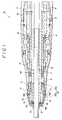
- Fig.1 is an enlarged longitudinal cross-sectional view showing the foremost part of a straight type handpiece equipped with a device for preventing intrusion of foreign matter into the handpiece according to an embodiment of the present invention.
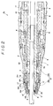
- Fig.2 is a cross-sectional view similar to Fig.1 and showing a straight type handpiece equipped with the device for preventing intrusion of foreign matter into the handpiece according to a modified embodiment of the present invention.
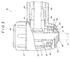
- Fig.3 is an enlarged longitudinal cross-sectional view showing the foremost part of an angle type handpiece equipped with the device for preventing intrusion of foreign matter into the handpiece shown in Fig.1.
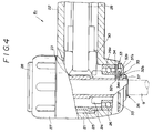
- Fig.4 is an enlarged longitudinal cross-sectional view similar to Fig.3 and showing an angle type dental handpiece equipped with the device for preventing intrusion of foreign matter into the handpiece shown in Fig.2.
- Fig.5 is an enlarged longitudinal cross-sectional view showing the foremost part of a conventional dental handpiece.
- Fig.1 shows a straight type dental handpiece A1, the main body of which is constituted by a sheath section 10, gripper section 11 and a nose section 12 at the middle at the rear end and at the foremost part of a shell, respectively.
- the nose section 12 is made up of a main nose member 12a and a nose cap 12b detachably mounted, such as by threading, on the one end of the main nose member 12a.
- the nose cap 12b is provided with four equiangularly spaced radial discharge ports 17.
- a spindle joint 2a constituting a bur sleeve adapted for receiving and securing a dental tool 9 in cooperation with a spindle 2 is mounted radially inwardly of the foremost part of the spindle 2.
- An end cap 14 as an additional rotating member is threadedly mounted on the outer end periphey of the spindle joint 2a.
- the end cap 14 has an inner flange section 14a contacting at the radially inner end thereof with the dental tool 9 and a radially outwardly projecting outer flange section 14b, and is intimately contacted with the outer peripheries of the spindle 2 and the spindle joint 2a.
- a gap section 15 communicating at one end with a tool inserting opening 8 and at the other end with a forward side ball bearing 3 is delimited between the outer periphery of the end cap 14 and the nose cap 12b.
- the spindle joint 2a and the end cap 14 are rotated in unison and, as a result of rotation of these components, a flow of air is induced around these components. Since the radius of rotation of the end cap 14 is larger than that of the spindle 2 or that of the spindle joint 2a, the circumferential velocity of the end cap 14 is higher than that of the spindle 2 or that of the spindle joint 2a.
- the radius of rotation of the outer flange section 14b is the largest and hence the air flow velocity around the outer periphery of the outer flange section 14b is the highest so that the air pressure around the outer flange section 14b is lowest in the vicinity of the foremost part of the handpiece A1.
- a foreign matter such as fine cut particles or chips are introduced at the gap of the tool inserting opening 8 under suction due to a pressure decrease induced within the handpiece A1.
- This foreign matter is introduced into the annular gap section 15 where the air pressure is lower to reach the area of the outer flange section 14b where the pressure is the smallest.
- the foreign matter is then expelled to outside through the discharge ports 17 under the centrifugal force of the end cap 14. In this manner, the foreign matter can be prevented from being intruded to the area of the forward side ball bearing 3.
- Fig.2 illustrates a dental handpiece A2 equipped with a modified embodiment of the intrusion preventing device according to the present invention.
- An end cap 14' has an inner flange section 14'a , having an end section abutting on the dental tool 9, and a cylindrical partition 14'b extending towards the rear side of the handpiece A2.
- An annular gap section 15a communicating with the tool inserting opening 8 is delimited between the nose cap 12b and the partition 14'b.
- a collar 16 On the inner periphery of the distal end of the main nose member 12a, there is provided a collar 16, as a fixed stationary partitioning member, having a cylindrical partition 16a extending towards the distal end of the handpiece A2.
- a second gap section 15b communicating with the gap section 15a is delimited between the partition 16a and the partition 14'b of the end cap 14'.
- the collar 16 has its proximal end secured to the main nose member 12a, so that, during rotation of the spindle 2, the collar 16 remains stationary.
- a third gap section 15c communicating with the area of the forward side bearing 3 and the second gap section 15b is defined between the inner periphery of the collar 16, and the outer peripheries of the spindle 2 and the spindle joint 2a.
- the spindle joint 2a and the end cap 14' are rotated in unison therewith and the air pressure within the handpiece A2 is lowered with rotation of these components. Since the radius of rotation of the end cap 14' is larger than that of the spindle 2 or that of the spindle joint 2a, the circumferential velocity of the end cap 14' is higher than that of the spindle 2 or that of the spindle joint 2a.
- the partition 16a of the collar 16 is positioned between the end cap 14' on one hand and the spindle 2 and the spindle joint 2a on the other, the aforementioned gap sections 15c and 15b where the air flows with different circumferential velocities are defined radially inwardly and outwardly of the partition 16a, respectively.
- the circumferential velocity through the gap section 15a defined on the outer periphery of the end cap 14' is higher than that through the gap section 15b defined on the inner periphery of the end cap 14' on account of the difference in the radius of rotation.
- the circumferential velocities through the gap sections 15c, 15b and 15a are higher in this order and hence the air pressures prevailing in these gap sections 15c, 15b and 15a are lower in the same order.
- the air pressure in the gap section 15a is the smallest in the vicinity of the foremost part of the handpiece A2.
- a foreign matter such as fine cut particles or chips are introduced at the gap of the tool inserting opening 8 under suction due to pressure decrease within the handpiece A2.
- This foreign matter is introduced into the gap section 15a where the air pressure is lower.
- it is hardly introduced into the gap sections 15b, 15c where the air pressure is higher than that in the gap section 15a.
- the foreign matter can hardly be introduced into the gap section 15c lying closely to the forward side ball bearing 3, thus reducing the damages to the bearing 3 caused by the forein matter, such as fine cut tooth particles or chips.
- An O-ring 18 is provided between the inner flange section 14'a and the spindle joint 2a for preventing the foreign matter from being intruded into the inside of the spindle 2 by the dental tool 9 during the exchanging operation of the dental tool 9.
- Fig.3 illustates another modified embodiment of the intrusion preventing device of the present invention, when applied to an angle type dental handpiece B1.
- the main members of the foremost part of the dental handpiece B1 include a head housing 21 adapted for attaching a dental tool 9, and a head housing jacket 22.
- a bur sleeve 23 for receiving and securing the dental tool 9 introduced through a tool inserting opening 36, a head gear 24 for roatationally driving the bur sleeve 23, and an upper ball bearing, not shown, and a lower ball bearing 26, arranged between both ends of a bearing spacer 25.
- a head cap 27 On the upper part of the head housing 21 is threadedly mounted a head cap 27 in the inside of which there is provided a chucking device, not shown, wherein the dental tool 9 may be detachably retained by manually thrusting or releasing a pushbutton 28.
- an end cap 31 as a rotating member, formed with a radially outwardly extending outer flange section 31a and having its one end threadedly secured to the bur sleeve 23.
- the end cap 31 may be rotated in this manner in unison with the bur sleeve 23.
- a gap section 32 communicating at one end with a downwardly opening port 35 and at the other end with the area of the lower ball bearing 26.
- the lower end of the head housing 21 is formed with a plurality of radial slits 33 as discharge ports communicating with the gap section 32.
- the end cap 31 When the bur sleeve 23 is rotated upon cutting, for example, a tooth, the end cap 31 is rotated in unison therewith and the air pressure in the inside of the handpiece is lowered due to rotation of these components.
- the radius of rotation of the outer flange section 31a of the end cap 31 is the largest, as long as the foremost part of the handpiece B1 and the near-by area are concerned, at the gap section 32 communicating from the port 35 to the lower ball bearing 26, so that the area around the gap section 32 is rotated with the maximum circumferential velocity with rotation of the bur sleeve 23.
- the air pressure in the gap section 32 around the outer flange section 31a is the smallest.
- a foreign matter such as fine cut particles or chips are introduced through the port 35 under suction due to pressure decrease within the handpiece B1.
- This foreign matter is introduced into the gap section 32 and thence into the area of the outer flange section 31a where the pressure is the smallest.
- the foreign matter is then expelled to outside through the slits 33 under the centrifugal force of the end cap 31.
- Fig.4 illustrates another modified embodiment of an intrusion preventing device for a dental handpiece B2 according to the present invention.
- an end cap 31' On the lower outer periphery of the bur sleeve 23, there is mounted an end cap 31', as a rotatable partitioning member, which is provided with an annular outer flange section 31'a having an L-shapred cross-section and which has its one end threadedly secured to the bur sleeve 23.
- the end cap 31' is rotated in unison with the bur sleeve 23.
- a gap section 32a communicating with the port 35 which is opened downwards.
- a plurality of radial slits 33 communicating with the gap section 32a.
- an outer race 26a of the lower ball bearing 26 and a collar 34 as a stationary partitioning members are placed on the lower inner periphery of the head housing 21, an outer race 26a of the lower ball bearing 26 and a collar 34 as a stationary partitioning members are placed.
- the collar 34 is pressed and secured against a radially inwardly extending lip of the head housing 21 under the downward thrusting pressure exerted by the bearing spacer 25.
- This downwardly directed thrusting pressure of the bearing spacer 25 is produced by threading the head cap 27 downwards and transmitted to the bearing spacer 25 by means of an outer race of the upper ball bearing, not shown. Since the collar 34 is pressed between the outer race 26a and the lower inner periphery of the head housing 21 so as to be secured unitarily to the head housing 21, the collar 32 remains stationary even when the bur sleeve 23 is rotated.
- a cylindrical partition 34a of the collar 34 is provided for extending along the longitudinal axis of the bur sleeve 23 and a second gap section 32b communicating with the gap section 32a is delimited between the outer periphery of the partition 34a and the inner periphery of the outer flange section 31'a.
- a third gap section 32c communicating at one end with the lower ball bearing 26 and at the other end with the second gap section 32b.
- the end cap 31' When the bur sleeve 23 is rotated upon cutting, for example, a tooth, the end cap 31' is rotated in unison therewith and the air pressure within the inside of the handpiece B2 is lowered as a result of rotation of these components.
- the outer flange section 31'a of the end cap 31' has the largest radius of rotation and hence exhibits the largest circumferential velocity during rotation of the bur sleeve 23. Since the partition 34a of the collar 34 is positioned between the bur sleeve 23 and the outer flange section 31'a, the air flow velocities are different on the radially inner and radially outer sides of the partition 34a.
- the air flow velocities through the gap sections 32c, 32b and 32a are higher in this order and the air pressures therein are lower in the same order. In this manner, as long as the distal end of the handpiece B2 is concerned, the air pressure within the gap section 32a is the smallest.
- the collar 34 as the stationary partitioning member is secured to the lip on the lower inner end of the head housing 21 under the downward thrusting pressure exerted by the outer race 26a of the lower ball bearing 26.
- the collar 34 may be secured in the inside of the head housing 21 directly or indirectly in any other way, if the collar remains stationary and non-rotatable during rotation of the bur sleeve 23.
Landscapes
- Health & Medical Sciences (AREA)
- Oral & Maxillofacial Surgery (AREA)
- Dentistry (AREA)
- Epidemiology (AREA)
- Life Sciences & Earth Sciences (AREA)
- Animal Behavior & Ethology (AREA)
- General Health & Medical Sciences (AREA)
- Public Health (AREA)
- Veterinary Medicine (AREA)
- Dental Tools And Instruments Or Auxiliary Dental Instruments (AREA)
Applications Claiming Priority (6)
| Application Number | Priority Date | Filing Date | Title |
|---|---|---|---|
| JP8788990 | 1990-08-24 | ||
| JP87889/90 | 1990-08-24 | ||
| JP9806290 | 1990-09-20 | ||
| JP98062/90 | 1990-09-20 | ||
| JP110519/90 | 1990-10-24 | ||
| JP1990110519U JPH0628086Y2 (ja) | 1990-08-24 | 1990-10-24 | 歯科用ハンドピースの防塵装置 |
Publications (2)
| Publication Number | Publication Date |
|---|---|
| EP0471916A1 true EP0471916A1 (de) | 1992-02-26 |
| EP0471916B1 EP0471916B1 (de) | 1995-06-28 |
Family
ID=27305623
Family Applications (1)
| Application Number | Title | Priority Date | Filing Date |
|---|---|---|---|
| EP91100070A Expired - Lifetime EP0471916B1 (de) | 1990-08-24 | 1991-01-02 | Vorrichtung zur Verhinderung des Eindringens von Fremdkörpern in dentale Handstücke |
Country Status (5)
| Country | Link |
|---|---|
| US (1) | US5074788A (de) |
| EP (1) | EP0471916B1 (de) |
| JP (1) | JPH0628086Y2 (de) |
| AT (1) | ATE124241T1 (de) |
| DE (1) | DE69110792T2 (de) |
Cited By (6)
| Publication number | Priority date | Publication date | Assignee | Title |
|---|---|---|---|---|
| EP0634147A1 (de) * | 1993-07-12 | 1995-01-18 | Nakanishi Inc. | Dentales Handstück mit einem Staubschutzelement |
| EP0689801A3 (de) * | 1994-07-01 | 1996-06-05 | Kaltenbach & Voigt | Ärztliches oder zahnärztliches Behandlungsinstrument mit Antrieb |
| EP0724867A2 (de) * | 1995-02-06 | 1996-08-07 | Nakanishi Inc. | Austauschbare Patrone für zahnärztliches Handstück |
| US5807108A (en) * | 1996-09-24 | 1998-09-15 | Dentalwerk Burmoos Gesellschaft M.B.H. | Dental handpiece |
| DE10313262A1 (de) * | 2003-03-24 | 2004-10-07 | Muss Dental Gmbh | Motorbetriebenes Handstück für medizinische Zwecke, insbesondere für ein dentales Labor |
| EP2345385A1 (de) | 2010-01-14 | 2011-07-20 | Bien-Air Holding SA | Vorrichtung zur Zentrifugalablenkung für chirurgisches oder zahntechnisches Handstück, das die Entfernung von Fremdkörpern ermöglicht |
Families Citing this family (16)
| Publication number | Priority date | Publication date | Assignee | Title |
|---|---|---|---|---|
| DE3929575A1 (de) * | 1989-09-06 | 1991-03-07 | Vascomed Kathetertech | Dilatationskatheter zum erweitern von blutgefaessen mit motorantrieb |
| US5267860A (en) * | 1992-08-28 | 1993-12-07 | Ingram Jr William L | Dental hygiene tool with shield and germicidal seals |
| JPH07121261B2 (ja) * | 1993-05-20 | 1995-12-25 | 株式会社中西歯科器械製作所 | 歯科用ハンドピース |
| US5779474A (en) * | 1994-06-09 | 1998-07-14 | Den-Tal-Ez, Inc. | Sudden stop mechanism and air-gap seal for dental handpiece |
| US5655906A (en) * | 1995-06-12 | 1997-08-12 | Micro Motors, Inc. | Autoclavable dental sonic scaler |
| US5823774A (en) * | 1996-01-31 | 1998-10-20 | Arthrotek, Inc. | Dynamically sealed surgical drill |
| DE50006806D1 (de) * | 1999-09-27 | 2004-07-22 | W & H Dentalwerk Buermoos Ges | Zahnärztliches oder chirurgisches Winkelstück |
| DE10130898C2 (de) * | 2001-06-27 | 2003-10-09 | Bahner Feinwerktechnik Gmbh | Handstück für ein medizinisches oder kosmetisches Bearbeitungsgerät |
| DE10130897C1 (de) * | 2001-06-27 | 2003-01-09 | Bahner Feinwerktechnik Gmbh | Handstück für ein Medizinisches oder kosmetisches Bearbeitungsgerät |
| EP1488076B1 (de) * | 2002-03-28 | 2016-07-13 | DENTSPLY International Inc. | Verfahren zum auswuchten des rotierenden turbinenelements eines dentalen handstücks |
| JP4160319B2 (ja) * | 2002-05-10 | 2008-10-01 | 株式会社モリタ製作所 | 歯科用切削装置及びサックバック防止方法 |
| JP4879164B2 (ja) * | 2005-03-22 | 2012-02-22 | 株式会社モリタ製作所 | ハンドピース及びそのサックバック防止方法 |
| WO2006110670A1 (en) * | 2005-04-12 | 2006-10-19 | Spring Health Products, Inc. | Electric dental handpiece and control system |
| US20100035205A1 (en) * | 2008-08-09 | 2010-02-11 | Daniel Wang | Non-90-Degree Ergonomically-Shaped Dental Prophylaxis Angle with a Straight Driving Shaft |
| DE102012005178B4 (de) | 2012-03-16 | 2022-02-24 | Hellmut Ruck Gmbh | Medizinisches oder kosmetisches Bearbeitungsgerät |
| US20150132713A1 (en) * | 2013-11-08 | 2015-05-14 | Dentalez, Inc. | Dental handpiece with vortex-washer-driven particulate discharge |
Citations (3)
| Publication number | Priority date | Publication date | Assignee | Title |
|---|---|---|---|---|
| CH596827A5 (de) * | 1975-12-22 | 1978-03-31 | Micro Mega Sa | |
| AT348100B (de) * | 1976-07-28 | 1979-01-25 | Kaltenbach & Voigt | Aerztliches, insbesondere zahnaerztliches handstueck |
| DE3402585A1 (de) * | 1984-01-26 | 1985-08-01 | Otto 3000 Hannover Muss | Handstueck zur aufnahme auswechselbarer dentalwerkzeuge |
Family Cites Families (5)
| Publication number | Priority date | Publication date | Assignee | Title |
|---|---|---|---|---|
| US2983519A (en) * | 1958-11-24 | 1961-05-09 | Staunt Martin | Chucks for dental handpieces |
| JPS53140894A (en) * | 1977-05-12 | 1978-12-08 | Nakanishi Shika Kikai Seisakus | Chuck open*close device for dental handpiece |
| CH640718A5 (de) * | 1980-05-13 | 1984-01-31 | Micro Mega Sa | Tete de contre-angle dentaire comprenant un dispositif empechant la penetration d'eau a l'interieur. |
| JPS6019689Y2 (ja) * | 1980-09-03 | 1985-06-13 | 長田電機工業株式会社 | 歯科用ハンドピ−ス |
| DE3828866C1 (de) * | 1988-08-25 | 1990-02-08 | Kaltenbach & Voigt Gmbh & Co, 7950 Biberach, De |
-
1990
- 1990-10-24 JP JP1990110519U patent/JPH0628086Y2/ja not_active Expired - Lifetime
-
1991
- 1991-01-02 EP EP91100070A patent/EP0471916B1/de not_active Expired - Lifetime
- 1991-01-02 AT AT91100070T patent/ATE124241T1/de not_active IP Right Cessation
- 1991-01-02 DE DE69110792T patent/DE69110792T2/de not_active Expired - Lifetime
- 1991-02-26 US US07/661,398 patent/US5074788A/en not_active Expired - Lifetime
Patent Citations (3)
| Publication number | Priority date | Publication date | Assignee | Title |
|---|---|---|---|---|
| CH596827A5 (de) * | 1975-12-22 | 1978-03-31 | Micro Mega Sa | |
| AT348100B (de) * | 1976-07-28 | 1979-01-25 | Kaltenbach & Voigt | Aerztliches, insbesondere zahnaerztliches handstueck |
| DE3402585A1 (de) * | 1984-01-26 | 1985-08-01 | Otto 3000 Hannover Muss | Handstueck zur aufnahme auswechselbarer dentalwerkzeuge |
Cited By (8)
| Publication number | Priority date | Publication date | Assignee | Title |
|---|---|---|---|---|
| EP0634147A1 (de) * | 1993-07-12 | 1995-01-18 | Nakanishi Inc. | Dentales Handstück mit einem Staubschutzelement |
| EP0689801A3 (de) * | 1994-07-01 | 1996-06-05 | Kaltenbach & Voigt | Ärztliches oder zahnärztliches Behandlungsinstrument mit Antrieb |
| EP0724867A2 (de) * | 1995-02-06 | 1996-08-07 | Nakanishi Inc. | Austauschbare Patrone für zahnärztliches Handstück |
| EP0724867A3 (de) * | 1995-02-06 | 1996-08-14 | Nakanishi Inc. | Austauschbare Patrone für zahnärztliches Handstück |
| US5807108A (en) * | 1996-09-24 | 1998-09-15 | Dentalwerk Burmoos Gesellschaft M.B.H. | Dental handpiece |
| DE10313262A1 (de) * | 2003-03-24 | 2004-10-07 | Muss Dental Gmbh | Motorbetriebenes Handstück für medizinische Zwecke, insbesondere für ein dentales Labor |
| EP2345385A1 (de) | 2010-01-14 | 2011-07-20 | Bien-Air Holding SA | Vorrichtung zur Zentrifugalablenkung für chirurgisches oder zahntechnisches Handstück, das die Entfernung von Fremdkörpern ermöglicht |
| EP2932934A1 (de) | 2010-01-14 | 2015-10-21 | Bien-Air Holding SA | Vorrichtung zur zentrifugalablenkung für chirurgisches oder zahntechnisches handstück, das die entfernung von fremdkörpern ermöglicht |
Also Published As
| Publication number | Publication date |
|---|---|
| US5074788A (en) | 1991-12-24 |
| JPH0628086Y2 (ja) | 1994-08-03 |
| EP0471916B1 (de) | 1995-06-28 |
| DE69110792D1 (de) | 1995-08-03 |
| JPH0488922U (de) | 1992-08-03 |
| DE69110792T2 (de) | 1995-11-16 |
| ATE124241T1 (de) | 1995-07-15 |
Similar Documents
| Publication | Publication Date | Title |
|---|---|---|
| EP0471916B1 (de) | Vorrichtung zur Verhinderung des Eindringens von Fremdkörpern in dentale Handstücke | |
| EP0625338B1 (de) | Handstück mit Lagerschutzelement | |
| JP3057564B2 (ja) | 歯科用ハンドピース | |
| US4365956A (en) | Cleaning cup | |
| JP4012280B2 (ja) | 手持ち工作機械における工具ホルダの交換装置 | |
| US6000940A (en) | Surgical bur shank and locking collet mechanism | |
| EP0455452B1 (de) | Zahnärztliches Handstück | |
| US5911579A (en) | Dental handpiece with baffle for stabilizing rolling bearing cage | |
| US3871097A (en) | Cooling system for a dental handpiece | |
| US5131846A (en) | Prophy cup shield | |
| GB2333477A (en) | Drill chuck | |
| US5947485A (en) | Collet assembly and manufacturing process | |
| US4353697A (en) | Dental handpiece and a connecting means thereof | |
| US5692903A (en) | Exchangeable cartridge for dental handpiece | |
| EP0020450A1 (de) | Zahnärztliches handstück und rotorpatronen-ersatz dafür | |
| JP3057567B1 (ja) | 歯科用プロフィ―ヘッド | |
| CN1268915A (zh) | 具有叶轮式冷却剂导流器的刀夹 | |
| US4796419A (en) | Bearing support for a twisting or spinning machine | |
| US4203221A (en) | Gas-driven handpiece having vibration isolating means | |
| US6595527B2 (en) | Chip-clearing drill chuck | |
| US4435161A (en) | Dental turbine | |
| WO2002045890A3 (en) | Chuck with spring leg dust cover | |
| US5628763A (en) | Surgical handpiece | |
| KR101510112B1 (ko) | 분진 토출구조를 갖는 핸드피스 | |
| JP5723163B2 (ja) | 手術用又は歯科用ハンドピース用の異物を除去する遠心偏向装置 |
Legal Events
| Date | Code | Title | Description |
|---|---|---|---|
| PUAI | Public reference made under article 153(3) epc to a published international application that has entered the european phase |
Free format text: ORIGINAL CODE: 0009012 |
|
| 17P | Request for examination filed |
Effective date: 19910102 |
|
| AK | Designated contracting states |
Kind code of ref document: A1 Designated state(s): AT CH DE FR GB IT LI |
|
| 17Q | First examination report despatched |
Effective date: 19930830 |
|
| ITF | It: translation for a ep patent filed |
Owner name: STUDIO INGG. FISCHETTI & WEBER |
|
| GRAA | (expected) grant |
Free format text: ORIGINAL CODE: 0009210 |
|
| AK | Designated contracting states |
Kind code of ref document: B1 Designated state(s): AT CH DE FR GB IT LI |
|
| REF | Corresponds to: |
Ref document number: 124241 Country of ref document: AT Date of ref document: 19950715 Kind code of ref document: T |
|
| REF | Corresponds to: |
Ref document number: 69110792 Country of ref document: DE Date of ref document: 19950803 |
|
| ET | Fr: translation filed | ||
| PLBE | No opposition filed within time limit |
Free format text: ORIGINAL CODE: 0009261 |
|
| STAA | Information on the status of an ep patent application or granted ep patent |
Free format text: STATUS: NO OPPOSITION FILED WITHIN TIME LIMIT |
|
| 26N | No opposition filed | ||
| REG | Reference to a national code |
Ref country code: GB Ref legal event code: IF02 |
|
| PGFP | Annual fee paid to national office [announced via postgrant information from national office to epo] |
Ref country code: GB Payment date: 20090124 Year of fee payment: 19 |
|
| PGFP | Annual fee paid to national office [announced via postgrant information from national office to epo] |
Ref country code: CH Payment date: 20090423 Year of fee payment: 19 |
|
| PGFP | Annual fee paid to national office [announced via postgrant information from national office to epo] |
Ref country code: FR Payment date: 20091216 Year of fee payment: 20 |
|
| PGFP | Annual fee paid to national office [announced via postgrant information from national office to epo] |
Ref country code: IT Payment date: 20100127 Year of fee payment: 20 |
|
| PGFP | Annual fee paid to national office [announced via postgrant information from national office to epo] |
Ref country code: AT Payment date: 20100107 Year of fee payment: 20 Ref country code: DE Payment date: 20100312 Year of fee payment: 20 |
|
| REG | Reference to a national code |
Ref country code: CH Ref legal event code: PL |
|
| GBPC | Gb: european patent ceased through non-payment of renewal fee |
Effective date: 20100102 |
|
| PG25 | Lapsed in a contracting state [announced via postgrant information from national office to epo] |
Ref country code: LI Free format text: LAPSE BECAUSE OF NON-PAYMENT OF DUE FEES Effective date: 20100131 Ref country code: CH Free format text: LAPSE BECAUSE OF NON-PAYMENT OF DUE FEES Effective date: 20100131 |
|
| PG25 | Lapsed in a contracting state [announced via postgrant information from national office to epo] |
Ref country code: GB Free format text: LAPSE BECAUSE OF NON-PAYMENT OF DUE FEES Effective date: 20100102 |
|
| PG25 | Lapsed in a contracting state [announced via postgrant information from national office to epo] |
Ref country code: DE Free format text: LAPSE BECAUSE OF EXPIRATION OF PROTECTION Effective date: 20110102 |