EP0471379A2 - Paketvermittlungsverfahren und -system mit selbstsuchendem Koppelfeld - Google Patents
Paketvermittlungsverfahren und -system mit selbstsuchendem Koppelfeld Download PDFInfo
- Publication number
- EP0471379A2 EP0471379A2 EP91113791A EP91113791A EP0471379A2 EP 0471379 A2 EP0471379 A2 EP 0471379A2 EP 91113791 A EP91113791 A EP 91113791A EP 91113791 A EP91113791 A EP 91113791A EP 0471379 A2 EP0471379 A2 EP 0471379A2
- Authority
- EP
- European Patent Office
- Prior art keywords
- transit
- packet
- lines
- local switching
- call
- Prior art date
- Legal status (The legal status is an assumption and is not a legal conclusion. Google has not performed a legal analysis and makes no representation as to the accuracy of the status listed.)
- Granted
Links
Images


Classifications
-
- H—ELECTRICITY
- H04—ELECTRIC COMMUNICATION TECHNIQUE
- H04L—TRANSMISSION OF DIGITAL INFORMATION, e.g. TELEGRAPHIC COMMUNICATION
- H04L12/00—Data switching networks
- H04L12/54—Store-and-forward switching systems
- H04L12/56—Packet switching systems
- H04L12/5601—Transfer mode dependent, e.g. ATM
- H04L12/5602—Bandwidth control in ATM Networks, e.g. leaky bucket
-
- H—ELECTRICITY
- H04—ELECTRIC COMMUNICATION TECHNIQUE
- H04L—TRANSMISSION OF DIGITAL INFORMATION, e.g. TELEGRAPHIC COMMUNICATION
- H04L49/00—Packet switching elements
- H04L49/25—Routing or path finding in a switch fabric
- H04L49/253—Routing or path finding in a switch fabric using establishment or release of connections between ports
- H04L49/254—Centralised controller, i.e. arbitration or scheduling
-
- H—ELECTRICITY
- H04—ELECTRIC COMMUNICATION TECHNIQUE
- H04L—TRANSMISSION OF DIGITAL INFORMATION, e.g. TELEGRAPHIC COMMUNICATION
- H04L12/00—Data switching networks
- H04L12/54—Store-and-forward switching systems
- H04L12/56—Packet switching systems
- H04L12/5601—Transfer mode dependent, e.g. ATM
- H04L2012/5619—Network Node Interface, e.g. tandem connections, transit switching
-
- H—ELECTRICITY
- H04—ELECTRIC COMMUNICATION TECHNIQUE
- H04L—TRANSMISSION OF DIGITAL INFORMATION, e.g. TELEGRAPHIC COMMUNICATION
- H04L12/00—Data switching networks
- H04L12/54—Store-and-forward switching systems
- H04L12/56—Packet switching systems
- H04L12/5601—Transfer mode dependent, e.g. ATM
- H04L2012/5629—Admission control
- H04L2012/5631—Resource management and allocation
- H04L2012/5632—Bandwidth allocation
-
- H—ELECTRICITY
- H04—ELECTRIC COMMUNICATION TECHNIQUE
- H04L—TRANSMISSION OF DIGITAL INFORMATION, e.g. TELEGRAPHIC COMMUNICATION
- H04L49/00—Packet switching elements
- H04L49/30—Peripheral units, e.g. input or output ports
- H04L49/3009—Header conversion, routing tables or routing tags
Definitions
- the present invention relates to subject matter described in application Serial No. 07/645491 filed January 24, 1991 and entitled "Packet Switching System Having Self-routing Switches" by Shirou Tanabe et al (the corresponding European Patent Application No. 91 100698.9), the disclosure of which is hereby incorporated by reference.
- the present invention relates to packet switching method and system and more particularly to packet switching method and system in a packet network comprising a plurality of nodes each including a self-routing switch.
- each cross-connect does not require any processor for call processing and hence reliability of the network as a whole can be improved.
- the path for which the capacity is secured in advance must be established semi-fixedly, thus decreasing utilization efficiency of network resources. More specifically, as compared to the network using the switching station as the transit node, the network cost is disadvantageously increased for the same performance (call block rate) and the call block rate is increased for the same network construction.
- An object of the invention is to provide packet switching system and packet network, each comprising a plurality of switching units, which are improved in call block rate.
- Another object of the invention is to provide packet switching system and method using the cross-connect which, as compared to the prior art, can decrease the network cost for the same performance (call block rate) and can decrease the call block rate for the same network scale.
- packet switching system and packet network each comprise a plurality of local switching nodes (or local switching units) each having the call control function and at least one transit node (or tandem unit) constructed of a cross-connect and operative to inter-connect the local nodes through transit lines, any particular local node establishes, relative to a different desired local node, a plurality of logical paths (virtual paths VP's) which pass through the transit node and to which bandwidths are not assigned semi-fixedly in advance, and used bandwidths are managed in respect of individual transit lines on which the logical paths are established.
- local switching nodes or local switching units
- transit node or tandem unit
- any particular local node includes: first storage means for storing information concerning port numbers of a plurality of transit lines (hereinafter referred to as transit line numbers) connecting the particular local node and transit nodes; second storage means for storing information indicative of the connection relation between all transit lines constituting the packet switching system and the transit nodes; means for notifying the information concerning the transit line numbers stored in the first storage means to a different local node standing for a partner for which logical paths to be established are destined; means for defining a plurality of logical paths which are to be established between the particular local node and the different local node and which pass through different transit nodes, on the basis of the information concerning the transit line numbers notified from the different local node and the information stored in the first and second storage means; and third storage means for storing information used to define logical paths which are being set or which have been set by the particular local
- any particular local node further includes: fourth storage means for managing the used status of bandwidth in respect of individual transit lines connected to the transit nodes; and means for responding, during call setting, to the used status of bandwidths of transit lines connected to the originating local node and the used status of bandwidths of transit lines connected to the terminating local node to determine lines which are assignable to the call.
- a packet switching method for use in a packet network having a plurality of local switching units each connected to a plurality of packet lines, and at least one cross-connect unit connected to each local switching unit through at least one transit line having a predetermined transmission capacity, comprises the following steps: a first step of defining, on each transit line, a plurality of virtual paths for interconnecting the plurality of local switching units through the cross-connect unit, without fixedly assigning communication bandwidths to individual virtual paths; a second step of storing, in respect of the individual transit lines, values of communication bandwidths assigned to virtual channels which have already been established in virtual paths present on the transit lines; a third step of checking, when a request for setting a new call is originated, communication bandwidths of a pair of first and second transit lines, on which virtual path exists on which a virtual channel for the call is to be set up, for their margin enough to accept assignment of a bandwidth requested by the call, the first transit line lying between the cross-connect unit and an originating local switching unit, and the second transit line lying between the
- the packet network has a plurality of cross-connect units each connected to the individual local switching units through at least one transit line having a predetermined transmission capacity
- a plurality of virtual paths are defined between each local switching unit and a different desired local switching unit through different cross-connect units
- an originating local switching unit connected to a packet line originating a new call selects a plurality of first transit lines each having a margin enough to accept assignment of a bandwidth requested by the call as candidates for originating transit lines on which a virtual channel for the call is to be established, and the selected candidates for transit liens are notified to a terminating local switching unit
- the terminating local switching unit selects a plurality of second transit lines each having a margin enough to accept assignment of the bandwidth requested by the call as candidates for terminating transit lines on which a virtual channel for the call is to be established, and collates the candidates for originating transit lines with the candidates for terminating transit lines to specify a pair of first and second transit lines on which exists a virtual path to form
- any particular local node can recognize combinations of logical paths which are to be established between the particular local node and a different local node, on the basis of numbers possessed by transit lines connected to the different local node and notified from the different local node, numbers possessed by transit lines connected to this local node and information indicative of the connection relation between all transit lines constituting the packet switching system and the transit nodes.
- each logical path is established with its bandwidth (transmission capacity) unsettled, and when establishment of a logical channel (virtual channel) is requested and if, at that time, the transmission capacity of a transit line on which a logical path exists on which the logical channel is to be established has a margin, the logical channel is established on the logical path, thereby making it possible to make the most of the bandwidth of each transit line.
- the terminating local node selects transit lines to be assigned with the logical channel, on the basis of the notified status of bandwidth assignment of transit lines and the status of bandwidth assignment of candidates for transit lines which are selected from transit lines connected to the terminating local node and which are settable with the logical channel and establishes the logical channel on a logical path present on the selected transit lines. It is to be noted that the terminating local node notifies the originating local node of the results of selection and after assignment of the logical channels, management information indicative of the status of bandwidth assignment of the transit lines is updated in both the local nodes.
- the above-described logical channel assignment can also be applied to a packet network or a packet switching system of the type in which part of logical paths are assigned with bandwidths semi-fixedly in advance but the remaining logical paths are not subjected to the bandwidth assignment.
- the logical paths may precedently be classified into logical paths having high priority class and logical paths having low priority class and in each transit node and each local node, switching processing of packets on the logical paths of high priority class may be carried out in preference to that of packets on the logical paths of low priority class.
- Fig. 2 shows an example of construction of a packet network to which the present invention is applied.
- the packet network comprises a plurality of local nodes 1-1 to 1-k generally designated by reference numeral 1 and each connected with a plurality of subscriber lines (optical fibers) 9-1 to 9-l or 9'-1 to 9'-l, generally designated by reference numeral 9, and a plurality of transit nodes 2-1 to 2-k generally designated by reference numeral 2 and operative to interconnect one local node to another through transit lines 10-1 to 10'-k, generally designated by reference numeral 10.
- the plurality of transit nodes may be ganged into a single tandem unit and the tandem unit may be used in combination with the plurality of local nodes to form a single, large-capacity packet switching system.
- Each local node 1 includes a plurality of line interfaces 8a (8a-1 to 8a-l or 8'a-1 to 8'a-l) adapted to perform terminating process for the respective subscriber lines 9 (9-1 to 9-l or 9'-1 to 9'-l) and label converting process for an input packet (input cell) from the individual subscriber lines 9 (9-1 to 9-l or 9'-1 to 9'-l), a plurality of line interfaces 8b (8b-1 to 8b-k or 8b'-1 to 8b'-k) connected to a plurality of transit lines 10 (10-1 to 10-k or 10'-1 to 10'-k) corresponding to the transit node 2-1 or 2-k, a self-routing switch 3 (3-1 or 3-k) being operative by self-routing to deliver (switch) an input packet from a line interface 8a or 8b to another line interface, a signal processor 5 (5-1 or 5-k) operative to perform terminating process of a control signal inputted through the respective line interfaces, and a central
- Each subscriber line 9 includes incoming lines 9a (9a-1 to 9a-l or 9a'-1 to 9a'-l) and outgoing lines 9b (9b-1 to 9b-l or 9b'-1 to 9b'-l), and each transit line 10 likewise includes incoming lines 10a (10a-1 to 10a-k or 10a'-1 to 10a'-k) and outgoing lines 10b (10b-1 to 10b-k or 10b'-1 to 10b'-k).
- Each transit node 2 includes a plurality of line interfaces 8c (8c-1 to 8c-k or 8c'-1 to 8c'-k) provided in association with the transit lines 10 (10-1 to 10'-k), a self-routing switch 4 (4-1 or 4-k), and a route management 7 (7-1 or 7-k) adapted to perform initialization of parameters in various tables to which each line interface refers.
- Any local node 1-i is connected to the plurality of transit nodes 2-1 to 2-k through the plurality of transit lines 10-1 to 10-k so that a plurality of routes passing through different transit nodes may exist between any two local nodes.
- Fig. 3 shows a circuit construction of the line interface 8 (8a, 8b or 8c).
- Each line interface includes an upward circuit 21 for transferring a cell inputted from the incoming line (9a, 10b or 10a) to an input line (11a, 12a or 13a) of the self-routing switch 3 or 4, and a downward circuit 22 for transferring a cell from an output line (11b, 12b or 13b) of the self-routing switch 3 or 4 to the outgoing line 9b of subscriber line or the outgoing line 10a or 10b of transit line.
- the downward circuit 22 is comprised of a synchronous circuit 32 adapted to perform synchronous controlling process for an input signal from the self-routing switch and an E/O converter 31B for converting an electrical signal delivered out of the synchronous circuit into an optical signal and transferring the optical signal to the outgoing line 9b, 10a or 10b.
- the upward circuit 21 is comprised of an O/E converter 31A for converting an optical signal inputted from the incoming line 9a, 10b or 10a into an electrical signal, a synchronous circuit 32 adapted to perform synchronous controlling process for the signal from the O/E converter, an input register 25 for temporarily holding the input packet (cell) delivered out of the synchronous circuit, a delay circuit 23 for delaying the input packet by a predetermined time and supplying the delayed input packet to an output register 24, and a label conversion circuit 26 connected between the input register 25 and output register 24.
- the input register 25 of the line interface 8a or 8b extracts a VCI (virtual channel identifier) from a header of the input packet to deliver it onto a data output line 27, and the input register 25 of the line interface 8c extracts a VPI (virtual path identifier) from a header of the input packet to deliver it onto a data output line 27.
- the label conversion circuit 26 is accessed by using the VCI or VPI as a read address and header information read out of the label conversion circuit 26 is supplied to the output register 24 through a data output line 28.
- the output register 24 converts a part of the header of the input packet supplied from the delay circuit 23 into the header information inputted from the data output line 28, so that the packet subjected to header conversion is delivered to the output line 11a, 12a or 13a.
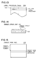
- Figs. 4 and 5 show the contents of label conversion tables 26a and 26b, respectively, in the line interfaces 8a and 8b constituting each local node
- Fig. 6 shows the contents of label conversion table 26c in the line interface 8c constituting each transit node.
- Each of the label conversion tables 26a and 26b provided in the local node is divided into a control signal area 260 and a user signal area 261.
- control signal area 260a of the label conversion table 26a is set as shown in Fig. 4, at an address position corresponding to an input VCI (VCIic) contained in each input control signal packet on the respective subscriber lines 9a (9a-1 to 9a-l; 9'a-1 to 9'a-l), with a VCI (VCIoc) which is unique to the signal processor 5 and a self-routing switch output port number (PT1) which is so fixed that each input control signal packet can be handed over to the signal processor 5.
- VCI VCI
- PT1 self-routing switch output port number
- User signal area 261a is set, at an address location corresponding to an input VCI (VCIi) contained in each input packet on the respective subscriber lines 9a (9a-1 to 9a-l; 9'a-1 to 9'a-l), with a VI (VCIo) which is effective between this local node and a terminating local node, a VPI (VPIo) which is effective between this local node and the transit nodes, and an output port number (PT1) for designating an output port of self-routing switch 3 to which the input packet is to be delivered.
- VCIi VCI
- VI VI
- VPI VPI
- PT1 output port number
- the label conversion table 26b on the transit line side has control signal area 260b which is structurally identical, as shown in Fig. 5, to the control signal area 260a of the label conversion table 26a.
- User signal area 261b is set, at an address location corresponding to a VCI (VCIi) contained in an input packet from the respective transit lines 10b (10b-1 to 10b-k; 10'b-1 to 10'b-k), with a VCI (VCIo) and VPI (VPIo) which are effective on the respective subscriber lines 9b (9b-1 to 9b-l; 9'b-1 to 9'b-l), and an output port number (PT1) for designating an output port of self-routing switch 3 to which the input packet is to be delivered.
- VCIi VCI
- VPI VPI
- the label conversion table 26c provided in the transit node 2 is set, at an address location corresponding to a VPI (VPIi) contained in an input packet from the respective transit lines 10a (10a-1 to 10a-k; 10'a-1 to 10'a-k), with a VPI (VPIo) which is effective between this transit node and a terminating local node, and an output port number (PT2) for designating an output port of self-routing switch 4 to which the input packet is to be delivered.
- VPIi VPI contained in an input packet from the respective transit lines 10a (10a-1 to 10a-k; 10'a-1 to 10'a-k)
- Each of the self-routing switches 3 and 4 is a packet switch which is so operated as to respond to an output port number (PT) contained in the header of an input packet to select an output line to which the input packet is to be delivered and it may be constructed of a single unit switch or a plurality of unit switches.
- PT output port number
- the self-routing switch 3 constituting the local node 1 includes a unit self-routing switch 51a for upward circuit connected to receive the output lines 11a (11a-1 to 11a-l) of upward circuits of the respective line interfaces 8a (8a-1 to 8a-l) on the subscriber side which are connected to the incoming subscriber lines 9a (9a-1 to 9a-l), and a unit self-routing switch 51b for downward circuit connected to receive the output lines 12a (12a-1 to 12a-k) of upward circuits of the respective line interfaces 8b (8b-1 to 8b-k) on the transit line side which are connected to the incoming transit lines 10b (10b-1 to 10b-k).
- a unit self-routing switch 51a for upward circuit connected to receive the output lines 11a (11a-1 to 11a-l) of upward circuits of the respective line interfaces 8a (8a-1 to 8a-l) on the subscriber side which are connected to the incoming subscriber lines 9a (9a-1 to 9a-l)
- the output lines 12b (12b-1 to 12b-k) of the unit self-routing switch 51a are connected to the downward circuits of respective line interfaces 8b (8b-1 to 8b-k) on the transit line side which are connected to the outgoing transit lines 10a (10a-1 to 10a-k), and the output lines 11b (11b-1 to 11b-l) of the unit self-routing switch 51b are connected to the downward circuits of respective line interfaces 8a (8a-1 to 8a-l) on the subscriber side which are connected to the outgoing subscriber lines 9b (9b-1 to 9b-l).
- the unit self-routing switches 51a and 51b are respectively connected with the signal processor 53 for upward circuit and signal processor 52 for downward circuit, and these signal processors 53 and 52 are coupled to the central controller 6 through a processor bus 29.
- Fig. 8A shows a basic format of 70-a of a packet.
- Each packet consists of user information area 71 and header 72, the header 72 having a VCI field, a VPI field and a PT field.
- Fig. 8B shows a format 70-b of a packet on the subscriber line and transit line.
- the VCI field and the VPI field are effective.
- Fig. 8C shows a format 70-c of a packet inside the local node 1.
- the header 72 all of the fields are effective with the PT field set with an output port number PT1 for designating an output port of self-routing switch 3 to which the packet is to be delivered.
- Fig. 8D shows a format 70-d of a packet inside the transit node 2.
- the header 72 only the VPI and PT fields are effective with the PT field set with an output port number PT2 for designating an output port of self-routing switch 4 to which the packet is to be delivered.
- VP construction is shown in Fig. 1.
- This example is directed to a packet network comprising three local nodes 1 (1-1 to 1-3) and three transit nodes 2 (2-1 to 2-3), wherein the VP is so constructed that a packet supplied from any particular local node to any transit node can be delivered to a desired line destined for a different local node. It is to be noted that the number of transit nodes 2 may be smaller than that of local nodes 1.
- the operation mode of the network is classified into a mode (basic mode procedure) in which a VC is set up on each VP without applying fixed bandwidth assignment to all VP's in advance, a mode (application mode procedure 1) in which a VC is set up on each VP while applying fixed bandwidth assignment to one or more of specified VPs in advance, and a mode (application mode procedure 2) in which high priority class/low priority class is set for the individual VP's in the basic mode procedure or application mode procedure 1.
- the local nodes 1, transit nodes 2 and transit lines 10 are assigned with local node numbers, transit node numbers and transit line numbers, that is, identification numbers for the nodes and lines which are consecutive numbers unique to the packet network.
- Figs. 9A and 9B show sequence of the VP establishment procedure in the basic mode procedure. This procedure enables each local node to define the VP as shown in Fig. 1 on individual transit lines upon commencement of working of the network.
- a local node operative to commence or start control operation in accordance with the VP establishment procedure is called an "originating local node" and a local node operative to respond to a control signal from the originating local node to execute the control operation in accordance with the VP establishment procedure is called a "terminating local node”.
- Central controller 6-i of an originating local node 1-i first looks up a local node map 100 as shown in Fig. 10 to retrieve identification numbers of the other local nodes constituting the current packet network (or packet switching system).
- the local node map 100 contains, at a bit position corresponding to each local node number, information of which "1" indicates that a local node having the corresponding local node number is packaged in the packet network and "0" indicates that such a local node as above is not packaged.
- the originating local node transmits to a desired transit node 2-n one of control packets which designates any local node retrieved from the local node map 100 as a terminating local node 1-j and which packet is defined as a "packet requesting a map of transit lines".
- the "packet requesting a map of transit lines" is fetched by a line interface 8c-i of the transit node 2-n and the contents (VPIi) of VPI field of the header is separated from the packet: and a value of the VPIi is supplied as a read address to the label conversion table 26c through the data line 27.
- the route management processor 7-n includes as shown in Fig. 12 a PT2 table 101 for storing the correspondence relation between the local node number and the output port number indicative of an output port destined for the local node.
- the route management processor 7-n looks up the PT2 table 101 to retrieve an output port number PT2 corresponding to the node number of the terminating local node 1-j contained in the user information of the received packet and sends again to the self-routing switch 4-n a packet subjected to the header conversion for replacement of the PT field of the received packet with the aforementioned PT2. In this manner, the "packet requesting a map of transit lines" is relayed to the terminating local node 1-j (step 81).
- the terminating local node 1-n determines an output port number PT1 corresponding to the value (VCIi) of VCI field of the packet from the label conversion table 26b, updates the PT field of the received packet to the output port number PT1 and thereafter supplies the updated packet to the self-routing switch 3-j (unit self-routing switch 51b in Fig. 7). In this manner, the "packet requesting a map of transit lines” can be fetched into the signal processor 52 through the unit self-routing switch 51b.
- the signal processor 52 has the function of performing such processes as assembling of the packet received from the self-routing switch into a frame, disassembling of the frame received from the central controller 6 into one or more packets and LAPD (link access procedure on the D-channel) and it converts information contained in the "packet requesting a map of transit lines" into a frame of predetermined format which in turn is transferred to the central controller 6.
- the central controller 6-j of the terminating local node 1-j includes a transit line map 102 as shown in Fig. 14 for storing the connection relation between all transit lines 10-1 to 10'-k in the network and this local node 1-j.
- the transit line map 102 stores, at a bit position corresponding to a transit line number, "1" to indicates that a transit line having that transit line number is connected to this local node 1-j and "0" to indicate that the transit line of that transit line number is not connected to this local node 1-j.
- the "packet notifying a map of transit lines” is relayed by means of line interface 8b-n and transit node 2-n so as to be transferred to the central controller 6-i of the originating local node 1-i (step 83).
- the central controller 6-i of the originating local node 1-i includes a transit node map 103 as shown in Fig. 15 for storing the correspondence relation between numbers of all transit lines in the network and numbers of transit nodes connected to these transit lines (numbers of transit nodes to be connected).
- the central controller 6-i On the basis of the transit line map transferred from terminating local node 6-j and the transit node map 103, the central controller 6-i recognizes the relation between the transit lines 10'-1 to 10'-k on the terminating local node side and the transit node numbers to be connected with these transit lines. Subsequently, on the basis of the transit line map 102 and transit node map 103 possessed by this local node, the central controller 6-i recognizes the relation between the transit lines 10-1 to 10-k and the transit node numbers to be connected with these transit lines. By matching the two recognition results, some sets of transit line numbers on the originating and terminating sides which are connected to the same transit node can be known. Such sets of originating and terminating side transit lines as connected to the same transit node are treated as objects of VP establishment.
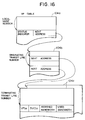
- the respective PIV table blocks 104c are prepared for the respective originating transit lines and each table block 104c stores, at an address location designated by the terminating transit line number, a management data record concerning the VP established on the transit line (including an identifier VPIo of VP, a virtual channel identifier for control SVCIo, a value of assigned bandwidth and a value of used bandwidth).
- the hunted VPI is stored as the VPIo. It is to be noted that the SVCIo is determined in accordance with the SVC establishment procedure to be described later.
- the "packet requesting VP assignment" is relayed by means of the transit node 2-n and transferred to the terminating local node 1-j (step 85).
- the central controller 6-j of the terminating local node 1-j hunts an unused, empty VPI in the terminating transit line designated by the "packet requesting VP assignment" (hereinafter a VPI to be used between the transit node and the terminating local node will be called a "terminating VPI") and necessary information is registered in the VP table as designated by 104a to 104c.
- the "packet notifying VP assignment" is relayed by means of the transit node 2-n and transferred to the originating local node 1-i (step 87).
- a processor bus is set up between the route management 7-n and the respective line interfaces 8c-1 to 8c-k, like the processor bus set up between the central controller 6 and the respective line interfaces 8a-1 to 8b-k in each local node 1 and the contents of the label conversion table is updated through the processor bus.
- Each local node repeats the above procedure for the respective originating side transit lines so that a plurality of VP's may be established between this local node and each terminating local node, thereby defining the VP construction of Fig. 1.
- a VC for control signal (hereinafter referred to as an SVC) used during call setting operation will now be described with reference to Figs. 9A and 9B. It is now assumed that a single SVC is established on each VP.
- the central controller 6-i of the originating local node 2-i hunts an SVCI unique to an originating side transit line (hereinafter, an SVCI used for a channel destined from line interface 8b-n of the originating local node to line interface 8b'-n of the terminating local line is called an "originating SVCI") and registers the hunted SVCI in an SVCIo field of the VP table 104c shown in Fig. 16.
- Each local node executes the above procedure until SVC's corresponding to all VP's are established thereon.
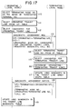
- the central controller 6-i of the originating local node 1-i selects a terminating local node number connected with the terminating terminal by looking up a dial number table (not shown) on the basis of a terminating terminal number (Telephone number) dialed by the originating terminal (step 110).
- the central controller 6-i accesses the VP table 104a by using the terminating local node number as a retrieval key and selects some originating transit lines on which the VP destined for the terminating local node is established by looking up a table block 104b designated by the address pointer (step 111). To this end, the table block 104b is sequentially accessed to determine a storage address at which pointer data is recorded.
- the central controller 6-i looks up a transit line bandwidth table 105 as shown in Fig. 18 for managing a used bandwidth in respect of each transit line to select a single or a plurality of candidates for originating transit lines to which a bandwidth requested by the originating terminal is assignable, from a plurality of originating transit lines having the VP destined for the terminating local node and determined from the table 104b (step 112).
- the central controller 6-j of the terminating local node 1-j takes a similar procedure to that taken by the originating local node to select candidates for terminating transit lines which can satisfy the requested bandwidth indicated in the user information area of the "packet requesting bandwidth assignment", from the plurality of terminating transit lines having the VP destined for the originating local node (steps 114 and 115).
- the central controller 6-j collates the candidates for terminating transit lines selected in the above step 115 with the candidates for originating transit lines notified by the "packet requesting bandwidth assignment" to determine a single transit line (VP) to which a transit node is connected in common (step 116).
- VP transit line
- step 116 When a plurality of local nodes have the same construction and they are connected in an orderly manner to transit nodes as shown in Fig. 1, it is possible to decide, by a number possessed by a transit line, which transit node the transit line is connected to.
- the aforementioned collation can be realized easily by, for example, expressing the candidates for originating transit lines and the candidates for terminating transit lines in such a map form that transit lines connected to the same transit node line at the same bit position.
- the central controller 6-i of the originating local node 1-i adds the presently assigned bandwidth to the used bandwidth field of record corresponding to the transit line determined in the originating local node (step 119).
- Figs. 9A and 9B the procedure for assigning a bandwidth to one or a plurality of specified VP's will now be described.
- bandwidth particular two local nodes are specified by, for example, the operator and a bandwidth to be secured for a VP between the two specified local nodes is designated.
- steps 80 to 83 Operations carried out in steps 80 to 83 are similar to those carried out in the basic mode procedure described previously.
- step 84 the same operation as that of the basic mode procedure is carried out, excepting that if the VP is to be assigned with the bandwidth, the assigned bandwidth is added to the used bandwidth field of the transit line bandwidth table 105 in the originating local node 1-i and registered in the VP table 104c, and ⁇ assigned bandwidth ⁇ is added to the user information area of the "packet requesting VP assignment".
- step 85 the same operation as that in the basic mode procedure is carried out and the operation carried out in step 86 is the same as that in the basic mode procedure with the exception that the assigned bandwidth is added to the used bandwidth field in the transit line bandwidth table 105 of the terminating local unit 1-j and that the assigned bandwidth is registered in the VP table 104c.
- steps 87 and 88 the same operation as that in the basic mode procedure is carried out.
- the SVC establishment procedure is the same as that in the basic mode procedure.
- the central controller 6-i of the originating local node 2-i determines a node number possessed by the terminating local node 2-j to which the terminating terminal is connected, from the dial number table on the basis of a terminating terminal number dialled by an originating terminal (step 120).
- the central controller 6-i selects a VP to which a bandwidth requested by the originating terminal is assignable from the VP table 104c (step 121) and adds the presently assigned bandwidth to the used bandwidth field in the VP table 104c (step 122).
- the terminating local node 1-j When receiving the packet notifying bandwidth assignment, the terminating local node 1-j adds the assigned bandwidth designated by the "packet notifying bandwidth assignment" to the used bandwidth field in the VP table 104c (step 124).
- the packet for control signal is of high priority class
- the packet for user signal is of low priority class
- a single VP for control signal (hereinafter referred to as an SVP) is established for each VP for user signal.
- the SVC exists in the VP for user signal but in the present embodiment, the SVC exists in the SVP.
- Fig. 20 is a diagram showing the VP establishment procedure taking high/low priority class into consideration.
- Process steps 80' to 92' in Fig. 20 correspond to steps 80 to 92 shown in Figs. 9A and 9B.
- Steps 80' to 83' covering the process in which the originating local node 1-i transmits the "packet requesting a map of transit lines" and receives the "packet notifying a map of transit lines" from the terminating local node 1-j have the same contents as steps 80 to 83 in Fig. 9A.
- the originating local node 1-j hunts an originating VPI and an originating SVPI.
- an address at which a VPI record is registered in the VP table 104c is set to be "terminating transit line number" x 2 and an address at which an SVPI record is registered in the VP table 104c is set to be ("terminating transit line number" x 2) + 1.
- the "packet notifying VP assignment" is relayed by means of the transit node so as to be transferred to the originating local node 1-i (step 87').
- Steps 89' to 92' covering the process in which the originating local node 1-i transmits the "packet instructing SVC assignment connection" and receives the "packet instructing SVC connection” from the terminating local node 1-j are the same as steps 89 to 92 in Figs. 9A and 9B, excepting that the SVC is established on the SVP.
- the procedure of assigning a bandwidth to a VC is the same as that in the basic mode procedure (or application mode procedure 1).
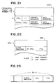
- a packet (Fig. 23) subjected to the label conversion process by means of the line interface 8c-i is fetched into a branch circuit 130-i through an input line 13a-i.
- the branch circuit 130-i distributes the packet to a high-priority unit self-routing switch 131 or a low-priority unit self-routing switch 132.
- the high-priority unit self-routing switch 131 switches the packet to a high priority class queue 133 (FIFO) corresponding to PT2
- the low-priority unit self-routing switch 132 switches the packet to a low priority class queue 134 (FIFO) corresponding to PT2.
- a read controller 135 reads packets from high priority class queues 133-1 - 133-k in preference to the packet of low priority class queues 134-1 - 134-k (for example, at a ratio of 1:2).
- the packet processing control including the bandwidth management for packet circuit and routing control is not carried out by the transit node but is effected by each local node, danger of occurrence of faults in the network or packet switching system comprised of the nodes can be managed to be distributed to thereby improve reliability of the system.
- each local node only the virtual (logical) path identifier is defined without precedently specifying the path capacity and when a logical connection (virtual channel VC) is established on any virtual path in accordance with a call setting request, management of margin bandwidth is effected for each physical line on which the virtual path exists so that the logical connection may be established if a margin bandwidth is present, thereby ensuring that as compared to the conventional network in which all virtual paths are assigned with bandwidths in advance, the network cost can be reduced for the same performance (call block rate) and the call block rate can be reduced for the same network construction.
- a logical connection virtual channel VC
- the status of used bandwidth on any line for connection and relay between the local and transit nodes is managed by a local node to which the line is connected so that a plurality of originating/terminating transit lines may be checked for their status of used bandwidth by a control signal communicated during call setting between an originating local node and a terminating local node so as to select an optimum route from the plurality of transit lines, thereby ensuring that as compared to the system in which the line is selected by means of only the originating local node, the call block rate can be reduced.
Applications Claiming Priority (2)
| Application Number | Priority Date | Filing Date | Title |
|---|---|---|---|
| JP2215712A JPH04229747A (ja) | 1990-08-17 | 1990-08-17 | パケット交換方法、およびパケット交換システム |
| JP215712/90 | 1990-08-17 |
Publications (3)
| Publication Number | Publication Date |
|---|---|
| EP0471379A2 true EP0471379A2 (de) | 1992-02-19 |
| EP0471379A3 EP0471379A3 (en) | 1992-10-07 |
| EP0471379B1 EP0471379B1 (de) | 1995-07-12 |
Family
ID=16676920
Family Applications (1)
| Application Number | Title | Priority Date | Filing Date |
|---|---|---|---|
| EP91113791A Expired - Lifetime EP0471379B1 (de) | 1990-08-17 | 1991-08-16 | Paketvermittlungsverfahren und -system mit selbstsuchendem Koppelfeld |
Country Status (5)
| Country | Link |
|---|---|
| US (1) | US5333131A (de) |
| EP (1) | EP0471379B1 (de) |
| JP (1) | JPH04229747A (de) |
| CA (1) | CA2049367C (de) |
| DE (1) | DE69111153T2 (de) |
Cited By (11)
| Publication number | Priority date | Publication date | Assignee | Title |
|---|---|---|---|---|
| EP0571153A2 (de) * | 1992-05-20 | 1993-11-24 | Xerox Corporation | Parallele Multi-Bit Koppelnetze |
| EP0571152A2 (de) * | 1992-05-20 | 1993-11-24 | Xerox Corporation | Verfahren zur Torenkombinierung in einem ATM-Koppelnetz zum Leitungsgruppierungszweck |
| EP0571166A2 (de) * | 1992-05-20 | 1993-11-24 | Xerox Corporation | Koppelnetz |
| EP0690596A1 (de) * | 1994-06-28 | 1996-01-03 | Hewlett-Packard Company | Verfahren und Gerät zur Plannung von Zellenübertragung von virtuellen Kanälen mit garantierter Bandbreite |
| WO1997002685A1 (fr) | 1995-07-03 | 1997-01-23 | Nippon Telegraph And Telephone Corporation | Reseau de communications a bande variable |
| EP0809382A1 (de) * | 1996-05-21 | 1997-11-26 | CS Technologies Informatiques | Verfahren zur Verknüpfung von Knoten eines echtzeitparallelen Rechners |
| EP0692892A3 (de) * | 1994-07-14 | 1998-07-22 | ITALTEL SOCIETA ITALIANA TELECOMUNICAZIONI s.p.a. | Verfahren und Ausrüstung zur Echtheitverwaltung von Kommunikationsmitteln in einem virtuellen Privatnetz in ATM-Technik |
| WO1999026382A1 (en) * | 1997-11-18 | 1999-05-27 | Cabletron Systems, Inc. | Hierarchical schedules for different atm traffic |
| US6167049A (en) * | 1997-11-18 | 2000-12-26 | Cabletron Systems, Inc. | Non-zero minimum cell rate for available bit rate ATM service |
| EP1158734A2 (de) * | 2000-05-23 | 2001-11-28 | Alcatel | Verfahren zur Zuordnung von logischen Verbindungen zu physchikalischen Verbindungen |
| GB2381408A (en) * | 2001-10-26 | 2003-04-30 | Orange Personal Comm Serv Ltd | Transit network in which each route between switching nodes is via a single transit node |
Families Citing this family (19)
| Publication number | Priority date | Publication date | Assignee | Title |
|---|---|---|---|---|
| JP2518515B2 (ja) * | 1993-05-27 | 1996-07-24 | 日本電気株式会社 | 高速コネクション設定パケット交換機 |
| DE4331579C2 (de) * | 1993-09-16 | 1995-07-06 | Siemens Ag | Verfahren zum Übertragen von Nachrichtenzellen über redundante virtuelle Pfadpaare eines ATM-Kommunikationsnetzes |
| JPH07245615A (ja) * | 1994-03-07 | 1995-09-19 | Fujitsu Ltd | Pvc接続型交換網における通信方式並びにpvc接続型交換網における送信装置及び同受信装置並びにpvc接続型交換網におけるpvc管理装置並びにpvc接続型交換網における伝送路帯域管理装置 |
| US5619497A (en) * | 1994-12-22 | 1997-04-08 | Emc Corporation | Method and apparatus for reordering frames |
| JPH08204723A (ja) * | 1995-01-30 | 1996-08-09 | Fujitsu Ltd | Atm網のclad装置 |
| US6002667A (en) | 1995-07-19 | 1999-12-14 | Fujitsu Network Communications, Inc. | Minimum guaranteed cell rate method and apparatus |
| JPH11512583A (ja) | 1995-09-14 | 1999-10-26 | フジツウ ネットワーク コミュニケーションズ,インコーポレイテッド | 広域atm網内のバッファ割付用送信側制御式フロー制御 |
| AU1697697A (en) | 1996-01-16 | 1997-08-11 | Fujitsu Limited | A reliable and flexible multicast mechanism for atm networks |
| JP2980031B2 (ja) * | 1996-08-12 | 1999-11-22 | 日本電気株式会社 | 再構成可能なネットワーク |
| JP2933021B2 (ja) * | 1996-08-20 | 1999-08-09 | 日本電気株式会社 | 通信網障害回復方式 |
| JPH1075247A (ja) * | 1996-08-29 | 1998-03-17 | Toshiba Corp | ノード装置及び仮想コネクション管理方法 |
| US5748905A (en) | 1996-08-30 | 1998-05-05 | Fujitsu Network Communications, Inc. | Frame classification using classification keys |
| US6097722A (en) * | 1996-12-13 | 2000-08-01 | Nortel Networks Corporation | Bandwidth management processes and systems for asynchronous transfer mode networks using variable virtual paths |
| JPH11136238A (ja) * | 1997-10-28 | 1999-05-21 | Fujitsu Ltd | パケット網における信号用帯域を制御する装置 |
| JP3075251B2 (ja) * | 1998-03-05 | 2000-08-14 | 日本電気株式会社 | 非同期転送モード交換網における仮想パス帯域分配システム |
| US6275493B1 (en) * | 1998-04-02 | 2001-08-14 | Nortel Networks Limited | Method and apparatus for caching switched virtual circuits in an ATM network |
| US6058116A (en) * | 1998-04-15 | 2000-05-02 | 3Com Corporation | Interconnected trunk cluster arrangement |
| JP4290320B2 (ja) * | 2000-09-28 | 2009-07-01 | 富士通株式会社 | ルーチング装置 |
| US20030033421A1 (en) * | 2001-08-02 | 2003-02-13 | Amplify.Net, Inc. | Method for ascertaining network bandwidth allocation policy associated with application port numbers |
Citations (2)
| Publication number | Priority date | Publication date | Assignee | Title |
|---|---|---|---|---|
| EP0274793A1 (de) * | 1986-12-19 | 1988-07-20 | Alcatel N.V. | Paketvermittlungsnetzwerk |
| EP0439098A2 (de) * | 1990-01-24 | 1991-07-31 | Hitachi, Ltd. | Paketvermittlungssystem mit selbstsuchenden Vermittlungen |
Family Cites Families (4)
| Publication number | Priority date | Publication date | Assignee | Title |
|---|---|---|---|---|
| JPH0683261B2 (ja) * | 1987-05-26 | 1994-10-19 | 富士通株式会社 | ヘッダ駆動形パケット交換機 |
| US5014266A (en) * | 1988-12-28 | 1991-05-07 | At&T Bell Laboratories | Circuit switching system for interconnecting logical links between packet switching networks |
| JP2892689B2 (ja) * | 1989-07-05 | 1999-05-17 | 株式会社日立製作所 | パケット通信網およびパケット交換機 |
| JPH03104451A (ja) * | 1989-09-19 | 1991-05-01 | Fujitsu Ltd | 多段リンク交換システムのルート切替え方式 |
-
1990
- 1990-08-17 JP JP2215712A patent/JPH04229747A/ja active Pending
-
1991
- 1991-08-16 CA CA002049367A patent/CA2049367C/en not_active Expired - Fee Related
- 1991-08-16 DE DE69111153T patent/DE69111153T2/de not_active Expired - Fee Related
- 1991-08-16 EP EP91113791A patent/EP0471379B1/de not_active Expired - Lifetime
- 1991-08-19 US US07/747,144 patent/US5333131A/en not_active Expired - Fee Related
Patent Citations (2)
| Publication number | Priority date | Publication date | Assignee | Title |
|---|---|---|---|---|
| EP0274793A1 (de) * | 1986-12-19 | 1988-07-20 | Alcatel N.V. | Paketvermittlungsnetzwerk |
| EP0439098A2 (de) * | 1990-01-24 | 1991-07-31 | Hitachi, Ltd. | Paketvermittlungssystem mit selbstsuchenden Vermittlungen |
Non-Patent Citations (6)
| Title |
|---|
| IEEE GLOBECOM 88, vol. 1, November 1988, pages 203-207; Florida, US; G. WOODRUFF et al.: "A congestion control framework for high speed integrated packetized transport" * |
| IEEE INT. CONF. ON COMMUNICATIONS '90, Atlanta, GA, 15th - 19th April 1990, vol. 2, pages 439-442, IEEE, New York, US; W. WANG et al.: "Bandwidth allocation for ATM networks" * |
| IEEE TRANSACTIONS ON COMMUNICATIONS, vol. 38, no. 8, August 1990, pages 1212-1222, IEEE, New York, US; K.-I. SATO et al.: "Broad-band ATM network architecture based on virtual paths" * |
| INTERNATIONAL JOURNAL OF DIGITAL AND ANALOG CABLED SYSTEMS, vol. 1, 1988, pages 257-262, John Wiley & Sons, Ltd, US; J.L. ADAMS: "The virtual path identifier and its applications for routeing and priority of connectionless and connection-orientated services" * |
| INTERNATIONAL SWITCHING SYMPOSIUM '90, Stockholm, 28th May - 1st June 1990, vol. 5, pages 21-26; T. KOINUMA et al.: "An ATM switching system based on a distributed control architecture" * |
| THE INTERNATIONAL SYMPOSIUM ON SUBSCRIBER LOOPS AND SERVICES - 1988,Boston, US, September 11-16, 1988, p. 217-221, I. Tokizawa et al. * |
Cited By (20)
| Publication number | Priority date | Publication date | Assignee | Title |
|---|---|---|---|---|
| EP0571153A3 (en) * | 1992-05-20 | 1997-10-22 | Xerox Corp | Multi-bit parallel switching networks |
| EP0571152A2 (de) * | 1992-05-20 | 1993-11-24 | Xerox Corporation | Verfahren zur Torenkombinierung in einem ATM-Koppelnetz zum Leitungsgruppierungszweck |
| EP0571166A2 (de) * | 1992-05-20 | 1993-11-24 | Xerox Corporation | Koppelnetz |
| EP0571153A2 (de) * | 1992-05-20 | 1993-11-24 | Xerox Corporation | Parallele Multi-Bit Koppelnetze |
| EP0571166A3 (en) * | 1992-05-20 | 1997-10-22 | Xerox Corp | A switching network |
| EP0571152A3 (en) * | 1992-05-20 | 1997-10-22 | Xerox Corp | Method for aggregating ports on an atm switch for the purpose of trunk grouping |
| EP0690596A1 (de) * | 1994-06-28 | 1996-01-03 | Hewlett-Packard Company | Verfahren und Gerät zur Plannung von Zellenübertragung von virtuellen Kanälen mit garantierter Bandbreite |
| US5579312A (en) * | 1994-06-28 | 1996-11-26 | Hewlett-Packard Company | Method and apparatus for scheduling the transmission of cells of guaranteed-bandwidth virtual channels |
| EP0692892A3 (de) * | 1994-07-14 | 1998-07-22 | ITALTEL SOCIETA ITALIANA TELECOMUNICAZIONI s.p.a. | Verfahren und Ausrüstung zur Echtheitverwaltung von Kommunikationsmitteln in einem virtuellen Privatnetz in ATM-Technik |
| EP0785652A4 (de) * | 1995-07-03 | 2001-07-11 | Nippon Telegraph & Telephone | Kommunikationsnetzwerk mit variabler breite |
| EP0785652A1 (de) * | 1995-07-03 | 1997-07-23 | Nippon Telegraph And Telephone Corporation | Kommunikationsnetzwerk mit variabler breite |
| WO1997002685A1 (fr) | 1995-07-03 | 1997-01-23 | Nippon Telegraph And Telephone Corporation | Reseau de communications a bande variable |
| EP0809382A1 (de) * | 1996-05-21 | 1997-11-26 | CS Technologies Informatiques | Verfahren zur Verknüpfung von Knoten eines echtzeitparallelen Rechners |
| FR2749092A1 (fr) * | 1996-05-21 | 1997-11-28 | Cs Technologies Informatiques | Procede d'interconnexion des noeuds d'un calculateur parallele temps reel |
| WO1999026382A1 (en) * | 1997-11-18 | 1999-05-27 | Cabletron Systems, Inc. | Hierarchical schedules for different atm traffic |
| US6167049A (en) * | 1997-11-18 | 2000-12-26 | Cabletron Systems, Inc. | Non-zero minimum cell rate for available bit rate ATM service |
| US6272109B1 (en) | 1997-11-18 | 2001-08-07 | Cabletron Systems, Inc. | Hierarchical schedules for different ATM traffic |
| EP1158734A2 (de) * | 2000-05-23 | 2001-11-28 | Alcatel | Verfahren zur Zuordnung von logischen Verbindungen zu physchikalischen Verbindungen |
| EP1158734A3 (de) * | 2000-05-23 | 2003-10-22 | Alcatel | Verfahren zur Zuordnung von logischen Verbindungen zu physchikalischen Verbindungen |
| GB2381408A (en) * | 2001-10-26 | 2003-04-30 | Orange Personal Comm Serv Ltd | Transit network in which each route between switching nodes is via a single transit node |
Also Published As
| Publication number | Publication date |
|---|---|
| DE69111153D1 (de) | 1995-08-17 |
| CA2049367A1 (en) | 1992-02-18 |
| JPH04229747A (ja) | 1992-08-19 |
| EP0471379A3 (en) | 1992-10-07 |
| DE69111153T2 (de) | 1996-03-07 |
| EP0471379B1 (de) | 1995-07-12 |
| US5333131A (en) | 1994-07-26 |
| CA2049367C (en) | 1997-06-24 |
Similar Documents
| Publication | Publication Date | Title |
|---|---|---|
| EP0471379B1 (de) | Paketvermittlungsverfahren und -system mit selbstsuchendem Koppelfeld | |
| EP0482551B1 (de) | ATM-Vermittlungseinheit | |
| EP0577959A1 (de) | Mobilfunksysteme | |
| EP0426269A1 (de) | Mobil-Kommunikationssystem | |
| KR20010024784A (ko) | 에이티엠 노드의 중앙 집중화된 대기 행렬 | |
| JPH06335079A (ja) | Atm網におけるセル多重化装置 | |
| EP1098479B1 (de) | Paketvermittlungssystem mit Selbständig routenauswählenden Schalteinheiten | |
| JPH09275400A (ja) | Atm交換システム | |
| JPH10107808A (ja) | セル交換システムにおける仮想コネクションの設定制御方式 | |
| JP2001527365A (ja) | Atmモードで様々なaalプロトコルを処理するためのテーブル | |
| US5740156A (en) | Packet switching system having self-routing switches | |
| JP3083540B2 (ja) | マルチプロセッサを用いた交換制御方式 | |
| US5999537A (en) | Packet switching system having self-routing switches | |
| US6611496B1 (en) | Next hop selection in ATM networks | |
| US5805592A (en) | ATM node and routing data registering apparatus | |
| EP1180874A1 (de) | Verfahren und vorrichtungen zum schreiben und lesen von nachrichten undsteuerungschaltungen zur speicheradressierung beim schreiben und lesen vonnachrichten veränderlicher länge | |
| JP3252831B2 (ja) | Atmにおけるipパケットルーティングプロセッサの分散処理方法及びその装置 | |
| JPH11127173A (ja) | 接続群を有するatmセル切換装置およびatmセル切換方法と、対応する入出力端末手段 | |
| US7058062B2 (en) | Packet switching system having self-routing switches | |
| JP3203537B2 (ja) | Atm網の交換処理制御方法 | |
| JPH11191779A (ja) | Atmスイッチ | |
| JP2741913B2 (ja) | Atm通信におけるルーティング制御方式 | |
| JP2001527362A (ja) | Atmノード用のセル処理ユニット及びその方法 | |
| JPH11341071A (ja) | パケット交換方法、及び、パケット交換システム | |
| JPH0750672A (ja) | Atm網のエリア指定呼設定方法 |
Legal Events
| Date | Code | Title | Description |
|---|---|---|---|
| PUAI | Public reference made under article 153(3) epc to a published international application that has entered the european phase |
Free format text: ORIGINAL CODE: 0009012 |
|
| AK | Designated contracting states |
Kind code of ref document: A2 Designated state(s): DE FR GB |
|
| PUAL | Search report despatched |
Free format text: ORIGINAL CODE: 0009013 |
|
| AK | Designated contracting states |
Kind code of ref document: A3 Designated state(s): DE FR GB |
|
| 17P | Request for examination filed |
Effective date: 19930325 |
|
| 17Q | First examination report despatched |
Effective date: 19930609 |
|
| GRAA | (expected) grant |
Free format text: ORIGINAL CODE: 0009210 |
|
| AK | Designated contracting states |
Kind code of ref document: B1 Designated state(s): DE FR GB |
|
| REF | Corresponds to: |
Ref document number: 69111153 Country of ref document: DE Date of ref document: 19950817 |
|
| ET | Fr: translation filed | ||
| PLBE | No opposition filed within time limit |
Free format text: ORIGINAL CODE: 0009261 |
|
| STAA | Information on the status of an ep patent application or granted ep patent |
Free format text: STATUS: NO OPPOSITION FILED WITHIN TIME LIMIT |
|
| 26N | No opposition filed | ||
| REG | Reference to a national code |
Ref country code: GB Ref legal event code: IF02 |
|
| PGFP | Annual fee paid to national office [announced via postgrant information from national office to epo] |
Ref country code: FR Payment date: 20020618 Year of fee payment: 12 |
|
| PGFP | Annual fee paid to national office [announced via postgrant information from national office to epo] |
Ref country code: GB Payment date: 20020806 Year of fee payment: 12 |
|
| PGFP | Annual fee paid to national office [announced via postgrant information from national office to epo] |
Ref country code: DE Payment date: 20021024 Year of fee payment: 12 |
|
| PG25 | Lapsed in a contracting state [announced via postgrant information from national office to epo] |
Ref country code: GB Free format text: LAPSE BECAUSE OF NON-PAYMENT OF DUE FEES Effective date: 20030816 |
|
| PG25 | Lapsed in a contracting state [announced via postgrant information from national office to epo] |
Ref country code: DE Free format text: LAPSE BECAUSE OF NON-PAYMENT OF DUE FEES Effective date: 20040302 |
|
| GBPC | Gb: european patent ceased through non-payment of renewal fee |
Effective date: 20030816 |
|
| PG25 | Lapsed in a contracting state [announced via postgrant information from national office to epo] |
Ref country code: FR Free format text: LAPSE BECAUSE OF NON-PAYMENT OF DUE FEES Effective date: 20040430 |
|
| REG | Reference to a national code |
Ref country code: FR Ref legal event code: ST |