EP0469631A2 - Ion pump and vacuum pumping unit using the same - Google Patents
Ion pump and vacuum pumping unit using the same Download PDFInfo
- Publication number
- EP0469631A2 EP0469631A2 EP91113057A EP91113057A EP0469631A2 EP 0469631 A2 EP0469631 A2 EP 0469631A2 EP 91113057 A EP91113057 A EP 91113057A EP 91113057 A EP91113057 A EP 91113057A EP 0469631 A2 EP0469631 A2 EP 0469631A2
- Authority
- EP
- European Patent Office
- Prior art keywords
- outer electrode
- thermionic emission
- emission source
- accelerating grid
- vessel
- Prior art date
- Legal status (The legal status is an assumption and is not a legal conclusion. Google has not performed a legal analysis and makes no representation as to the accuracy of the status listed.)
- Granted
Links
Images

Classifications
-
- H—ELECTRICITY
- H01—ELECTRIC ELEMENTS
- H01J—ELECTRIC DISCHARGE TUBES OR DISCHARGE LAMPS
- H01J41/00—Discharge tubes for measuring pressure of introduced gas or for detecting presence of gas; Discharge tubes for evacuation by diffusion of ions
- H01J41/12—Discharge tubes for evacuating by diffusion of ions, e.g. ion pumps, getter ion pumps
- H01J41/14—Discharge tubes for evacuating by diffusion of ions, e.g. ion pumps, getter ion pumps with ionisation by means of thermionic cathodes
Abstract
Description
- The present invention relates to an exhaust apparatus and a vacuum pumping unit including the exhaust apparatus, which are specifically adapted for discharging a gas in a vacuum vessel to produce an ultrahigh vacuum in the semiconductor process or the like.
- Fig. 3 conceptionally illustrates a prior art vacuum equipment including the high vacuum pump, wherein a
vacuum chamber 1 is connected to avacuum pump 2 through anexhaust pipe 3. Thevacuum pump 2, which comprises, for example, a turbo molecular pump, an oil diffusion pump, an ion pump and the like and, exhausts only the gas molecules which fly into theexhaust pipe 3 from thevacuum chamber 1. - However, in the above-constructed vacuum equipment, when a turbo molecular pump is used to exhaust a gas with a low compression ratio such as hydrogen, helium or the like, gas molecules may diffuse back to a high vacuum side i.e. to the
vacuum chamber 1 and, thus causes a decrease in vacuum level. - In the case of an oil diffusion pump, the gas molecules, which were once exhausted by the pump, may flow back into the vacuum chamber and further, the vapor of pumping oil heated also diffuses back. Thus vacuum level decreases.
- In the case of the ion pump, gas molecules absorbed into a titanium wall of the pump are desorbed and flow back into the vacuum chamber, thus reducing a vacuum level.
- In the prior art, no effective means were available against the back diffusion of gas molecules with a low compression ratio or desorbed gas molecules from the vacuum pump. Nevertheless, oil vapor of the oil diffusion pump may be prevented only by providing a cold trap with liquid nitrogen, however, complete prevention for any counterflow has been substantially difficult.
- The present invention has been carried out in view of the above circumstances, and its object is to provide an exhaust apparatus capable of obtaining a high degree of vacuum by exhausting gas molecules in the vacuum chamber through ionization and acceleration of the gas molecules.
- Then, another object of the present invention is to provide a vacuum pumping unit for an exhaust apparatus which is combined with an auxiliary pump set on a back pressure side for the pumping unit. The vacuum pumping unit is capable of producing a high degree of vacuum by ionization and acceleration of the gas molecules in a vacuum chamber toward the auxiliary pump, and also by ionization and acceleration of gas molecules which flow back from the auxiliary pump toward the auxiliary pump.
- The above object of the present invention is attained by an exhaust apparatus comprising a thermionic emission source, an electron accelerating grid surrounding the thermionic emission source, an outer electrode surrounding the electron accelerating grid, an ion accelerating grid intersecting an axis of the outer electrode and installed apart from the outer electrode, a vessel for containing said thermionic emission source, said electron accelerating grid, said outer electrode, and said ion accelerating grid therein, a magnet disposed outside of the vessel to generate a magnetic field almost parallel to the axis of said outer electrode, a power supply for heating said thermionic emission source, a first DC power supply for applying a voltage between said electron accelerating grid, said outer electrode and said thermionic emission source, a second DC power supply for applying a voltage between said outer electrode and said ion accelerating grid so as to get said outer electrode positive.
- Further, the above object of the present invention is attained by an exhaust apparatus comprising a thermionic emission source, an outer electrode surrounding the thermionic emission source, an ion accelerating grid intersecting an axis of the outer electrode and installed apart from the outer electrode, a vessel for containing said thermionic emission source, said outer electrode, and said ion accelerating grid therein, a magnet disposed outside of the vessel for generating a magnetic field almost parallel with the axis of said outer electrode, a power supply for heating said thermionic emission source, a first DC power supply for applying a voltage between said outer electrode and said thermionic emission source, a second DC power source for applying a voltage between said outer electrode and said ion accelerating grid so as to get said outer electrode positive.
- Then, the other object of the present invention is attained by a vacuum pumping unit including an arbitrary vacuum pump and an exhaust apparatus, in which said exhaust apparatus comprises a thermionic emission source, an electron accelerating grid surrounding the thermionic emission source, an outer electrode surrounding the electron accelerating grid, an ion accelerating grid intersecting an axis of the outer electrode and installed apart from the outer electrode, a vessel containing said thermionic emission source, said electron accelerating grid, said outer electrode, and said ion accelerating grid therein, a magnet disposed outside of the vessel and generating a magnetic field almost parallel to the axis of said outer electrode, a power supply for heating said thermionic emission source, a first DC power supply for applying a voltage between said electron accelerating grid, said outer electrode and said thermionic emission source, a second DC power supply for applying a voltage between said outer electrode and said ion accelerating grid so as to get said outer electrode positive are comprised, is interposed between said vacuum pump and a vacuum vessel to be evacuated.
- Further, the other object of the present invention is attained by a vacuum pumping unit including an arbitrary vacuum pump and an exhaust apparatus, in which a thermionic emission source, an outer electrode surrounding the thermionic emission source, an ion accelerating grid intersecting an axis of the outer electrode and installed apart from the outer electrode, a vessel for containing said thermionic emission source, said outer electrode, and said ion accelerating grid therein, a magnet disposed outside of the vessel and generating a magnetic field almost parallel to the axis of said outer electrode, a power supply for heating said thermionic emission source, a first DC power supply for impressing a voltage between said outer electrode and said thermionic emission source, a second DC power supply for applying a voltage between said outer electrode and said ion accelerating grid so as to get said outer electrode positive are comprised, and which is interposed between said vacuum pump and a vacuum vessel to be evacuated.
- According to the exhaust apparatus and the vacuum pumping unit of the present invention, since gas molecules are ionized by electron bombardment and are accelerated toward the auxiliary pump, the backflow of gas molecules from an auxiliary vacuum pump can be completely prevented to thereby realize a high degree of vacuum.
- The features and advantages for the present invention will become more apparent from the following description in conjunction with figures for illustrative examples.
- Fig. 1 is a block diagram for a vacuum pumping unit including an exhaust apparatus according to a one embodiment of the present invention;
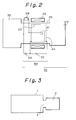
- Fig. 2 is a block diagram for another embodiment of the present invention;
- and Fig. 3 is a drawing for conceptionally illustrating a prior art vacuum exhaust equipment.
- In Figure 1, a
reference number 50 denotes an exhaust apparatus according to the present invention, and 100 denotes a vacuum pumping unit, thevacuum pumping unit 100 comprising a combination of theexhaust apparatus 50 with anarbitrary vacuum pump 31 provided on a back pressure side of theexhaust apparatus 50. - The
exhaust apparatus 50 comprises a hairpin shapedthermionic emission filament 21 as a thermionic emission source, a cylindricalelectron accelerating grid 22, a cylindricalouter electrode 23, an ion acceleratingflat grid 24, avessel 25, anelectromagnet 26, apower supply 28 for heating thefilament 21, an electron acceleratingDC power supply 29, and an ion acceleratingDC power supply 30, and the exhaust apparatus is interposed between avacuum vessel 32 to be evacuated and thevacuum pump 31 which operates as an auxiliary pump. - The
thermionic emission filament 21, theelectron accelerating grid 22, theouter electrode 23, and theion accelerating grid 24 are each disposed within thevessel 25. - The
filament 21 is disposed nearly at the center of thevessel 25, and is also disposed along a longitudinal axis of the vessel. - The
electron accelerating grid 22 is disposed surrounding thefilament 21, and theouter electrode 23 is disposed surrounding theelectron accelerating grid 22. - Then, the
ion accelerating grid 24 intersects an axis of theouter electrode 23 perpendicularly and is disposed on thevacuum pump 31 side apart somewhat from theouter electrode 23. - The
electromagnet 26, thepower supply 28, the electron acceleratingDC power supply 29, and the ion acceleratingDC power supply 30 are disposed out of thevessel 25, and theelectromagnet 26 disposed along a peripheral portion of thevessel 25 generates a DC magnetic field almost parallel with the axis of theouter electrode 23 in thevessel 25. - The
DC power supply 29 is connected between thefilament 21, theelectron accelerating grid 22 and theouter electrode 23, and applies a voltage so as to get thefilament 21 in negative potential. - The ion accelerating
DC power supply 30 is connected between theelectron accelerating grid 22, theouter electrode 23 and theion accelerating grid 24, which applied a voltage so as to get theouter electrode 23 in positive potential. - Then, a current and a voltage from the
power supplies elements vessel 25. - When the
filament 21 is heated by thepower supply 28, thefilament 21 emits thermal electrons. The emitted electrons are accelerated toward theelectron accelerating grid 22, and obtain a sufficient energy. Then they pass through theelectron accelerating grid 22. A magnetic field which orthogonally crosses the direction of the electrons movement is applied by theelectromagnet 26 within a space between theelectron accelerating grid 22 and theouter electrode 23, and thus the electrons move in a circular motion within the plane perpendicular to an axis of theouter electrode 23 while moving toward theouter electrode 23. Due to the circular motion of the electrons, a path of the electrons to reach theouter electrode 23 becomes longer, and thus the electrons easily come to collide with a lot of gas molecules and produce a large quantity of ions. The produced ions are accelerated toward theion accelerating grid 24, and exhausted through thepump 31. - On the other hand, the gas molecules flowing back or desorbed from the
vacuum pump 31 toward a high vacuum side are ionized and accelerated likewise in the manner stated above by theexhaust apparatus 50 and returned to thevacuum pump 31, therefore a high vacuum level is attained in the vacuum vessel. - In the prior art, when an evacuation is carried out only by the
vacuum pump 31, only gas molecules coming into the exhaust pipe are exhausted. However, since the gas molecules are ionized and accelerated for exhaust by the above-mentioned operation of the invention, an exhaust efficiency is increased and a high vacuum level is obtained. - Fig. 2 represents an exhaust apparatus and a vacuum pumping unit according to another embodiment of the present invention.
- The embodiment comprises a structure almost same as the embodiment shown in Fig. 1. As the same reference numbers represent the same constituents and operation in Fig. 1 and Fig. 2, repetitious descriptions will be omitted here.
- In Fig. 2, a
reference number 60 denotes an exhaust apparatus, 110 denotes a vacuum pumping unit which operates on theexhaust apparatus 60. Thevacuum pumping unit 110 consists of theexhaust apparatus 60 and thearbitrary vacuum pump 31 provided on a back pressure side of theexhaust apparatus 60. - In the
exhaust apparatus 60 of this embodiment, theelectron accelerating grid 22 in Fig. 1 is omitted. That is, theexhaust apparatus 60 has only the hairpin shapedthermionic emission filament 21 as a thermionic emission source and theouter electrode 23 surrounding thefilament 21 concentrically disposed within thevessel 25. - In Fig. 2, thermal electrons emitted from the heated
filament 21 are attracted toward theouter electrode 23, and make a circular orbit under the magnetic field generated by theelectromagnet 26. As the electrons run on a long path because of the circular orbit until the reach of theelectrode 23, they collide with a lot of gas molecules to produce a large quantity of ions. The produced ions are accelerated toward theion accelerating grid 24 and are exhausted by thepump 31. As a result, the gas molecules are exhausted by thevacuum pump 31 operating as an auxiliary exhaust means. - Thus, the present embodiment has a difference partly in construction and operation from the embodiment of Fig. 1, but, an exhaust effect is same.
- As described above, according to the exhaust apparatus and the vacuum pumping unit of the present invention, ionization and acceleration of gas molecules which come in the
vessel 25 by diffusion from thevessel 32 to be evacuated and by back diffusion from anauxiliary vacuum pump 31 can realize a high degree of vacuum.
Claims (26)
Applications Claiming Priority (2)
| Application Number | Priority Date | Filing Date | Title |
|---|---|---|---|
| JP2205224A JPH0675386B2 (en) | 1990-08-03 | 1990-08-03 | High vacuum device and vacuum pump device using the high vacuum device |
| JP205224/90 | 1990-08-03 |
Publications (3)
| Publication Number | Publication Date |
|---|---|
| EP0469631A2 true EP0469631A2 (en) | 1992-02-05 |
| EP0469631A3 EP0469631A3 (en) | 1992-07-01 |
| EP0469631B1 EP0469631B1 (en) | 1996-07-17 |
Family
ID=16503470
Family Applications (1)
| Application Number | Title | Priority Date | Filing Date |
|---|---|---|---|
| EP91113057A Expired - Lifetime EP0469631B1 (en) | 1990-08-03 | 1991-08-02 | Ion pump and vacuum pumping unit using the same |
Country Status (4)
| Country | Link |
|---|---|
| EP (1) | EP0469631B1 (en) |
| JP (1) | JPH0675386B2 (en) |
| AT (1) | ATE140560T1 (en) |
| DE (1) | DE69120874T2 (en) |
Cited By (4)
| Publication number | Priority date | Publication date | Assignee | Title |
|---|---|---|---|---|
| EP0499239A2 (en) * | 1991-02-12 | 1992-08-19 | Ebara Corporation | Ion pump and vacuum pumping unit using the same |
| US5240381A (en) * | 1990-08-03 | 1993-08-31 | Ebara Corporation | Exhaust apparatus and vacuum pumping unit including the exhaust apparatus |
| US5480286A (en) * | 1990-08-03 | 1996-01-02 | Ebara Corporation | Exhaust apparatus and vacuum pumping unit including the exhaust apparatus |
| CN109707612A (en) * | 2018-11-28 | 2019-05-03 | 中国科学院近代物理研究所 | A kind of ionic pump performance test and optimization device and its test and optimization method |
Families Citing this family (1)
| Publication number | Priority date | Publication date | Assignee | Title |
|---|---|---|---|---|
| WO2014182333A1 (en) * | 2013-05-09 | 2014-11-13 | Fomani Arash Akhavan | Vacuum pumps for producing adsorbate-free surfaces |
Citations (3)
| Publication number | Priority date | Publication date | Assignee | Title |
|---|---|---|---|---|
| DE596017C (en) * | 1932-06-24 | 1934-04-25 | Linde Eismasch Ag | Process for achieving a pumping effect in gases |
| US2578009A (en) * | 1947-12-23 | 1951-12-11 | Rca Corp | Electronic high vacuum apparatus |
| GB684710A (en) * | 1950-07-19 | 1952-12-24 | Ass Elect Ind | Improvements relating to high vacuum pumps |
-
1990
- 1990-08-03 JP JP2205224A patent/JPH0675386B2/en not_active Expired - Lifetime
-
1991
- 1991-08-02 AT AT91113057T patent/ATE140560T1/en not_active IP Right Cessation
- 1991-08-02 EP EP91113057A patent/EP0469631B1/en not_active Expired - Lifetime
- 1991-08-02 DE DE69120874T patent/DE69120874T2/en not_active Expired - Fee Related
Patent Citations (3)
| Publication number | Priority date | Publication date | Assignee | Title |
|---|---|---|---|---|
| DE596017C (en) * | 1932-06-24 | 1934-04-25 | Linde Eismasch Ag | Process for achieving a pumping effect in gases |
| US2578009A (en) * | 1947-12-23 | 1951-12-11 | Rca Corp | Electronic high vacuum apparatus |
| GB684710A (en) * | 1950-07-19 | 1952-12-24 | Ass Elect Ind | Improvements relating to high vacuum pumps |
Cited By (6)
| Publication number | Priority date | Publication date | Assignee | Title |
|---|---|---|---|---|
| US5240381A (en) * | 1990-08-03 | 1993-08-31 | Ebara Corporation | Exhaust apparatus and vacuum pumping unit including the exhaust apparatus |
| US5480286A (en) * | 1990-08-03 | 1996-01-02 | Ebara Corporation | Exhaust apparatus and vacuum pumping unit including the exhaust apparatus |
| EP0499239A2 (en) * | 1991-02-12 | 1992-08-19 | Ebara Corporation | Ion pump and vacuum pumping unit using the same |
| EP0499239A3 (en) * | 1991-02-12 | 1993-03-03 | Ebara Corporation | Ion pump and vacuum pumping unit using the same |
| CN109707612A (en) * | 2018-11-28 | 2019-05-03 | 中国科学院近代物理研究所 | A kind of ionic pump performance test and optimization device and its test and optimization method |
| CN109707612B (en) * | 2018-11-28 | 2020-01-17 | 中国科学院近代物理研究所 | Ion pump performance testing and optimizing device and testing and optimizing method thereof |
Also Published As
| Publication number | Publication date |
|---|---|
| ATE140560T1 (en) | 1996-08-15 |
| EP0469631A3 (en) | 1992-07-01 |
| JPH0492353A (en) | 1992-03-25 |
| JPH0675386B2 (en) | 1994-09-21 |
| EP0469631B1 (en) | 1996-07-17 |
| DE69120874D1 (en) | 1996-08-22 |
| DE69120874T2 (en) | 1997-02-27 |
Similar Documents
| Publication | Publication Date | Title |
|---|---|---|
| US4739214A (en) | Dynamic electron emitter | |
| US5899666A (en) | Ion drag vacuum pump | |
| EP0469631B1 (en) | Ion pump and vacuum pumping unit using the same | |
| KR100307070B1 (en) | High speed atomic beam supply source | |
| US5727929A (en) | Exhaust apparatus and vacuum pumping unit including the exhaust apparatus | |
| JPH05121194A (en) | High-speed atomic beam source | |
| JPH04277500A (en) | Source of high speed atomic ray | |
| US5240381A (en) | Exhaust apparatus and vacuum pumping unit including the exhaust apparatus | |
| JP3129226B2 (en) | Method of manufacturing field emission type cold cathode mounted device | |
| EP0499239A2 (en) | Ion pump and vacuum pumping unit using the same | |
| US3022933A (en) | Multiple electron beam ion pump and source | |
| JP3140636B2 (en) | Plasma generator | |
| JPH06101319B2 (en) | High vacuum device and vacuum pump device using the high vacuum device | |
| JPH02121233A (en) | Ion source | |
| JP2855160B2 (en) | Ion source | |
| JP3154018B2 (en) | Ion source | |
| JPH0473896A (en) | Plasma generating device | |
| JPH01161699A (en) | High-speed atomic beam source | |
| JPS6127053A (en) | Electron beam source | |
| JPH0837098A (en) | Plasma generating device | |
| JPH06289193A (en) | Fast atomic beam source | |
| Zavjalov et al. | Problems of cathode design and breakdown avoidance relevant to high-power broadband gas-plasma-filled microwave sources | |
| JPS63307655A (en) | Electron irradiation device | |
| JPH07288199A (en) | Synchrotron ring | |
| Uman et al. | Double chamber ion source |
Legal Events
| Date | Code | Title | Description |
|---|---|---|---|
| PUAI | Public reference made under article 153(3) epc to a published international application that has entered the european phase |
Free format text: ORIGINAL CODE: 0009012 |
|
| AK | Designated contracting states |
Kind code of ref document: A2 Designated state(s): AT BE CH DE DK ES FR GB GR IT LI LU NL SE |
|
| PUAL | Search report despatched |
Free format text: ORIGINAL CODE: 0009013 |
|
| AK | Designated contracting states |
Kind code of ref document: A3 Designated state(s): AT BE CH DE DK ES FR GB GR IT LI LU NL SE |
|
| 17P | Request for examination filed |
Effective date: 19921113 |
|
| 17Q | First examination report despatched |
Effective date: 19941221 |
|
| GRAH | Despatch of communication of intention to grant a patent |
Free format text: ORIGINAL CODE: EPIDOS IGRA |
|
| GRAH | Despatch of communication of intention to grant a patent |
Free format text: ORIGINAL CODE: EPIDOS IGRA |
|
| GRAA | (expected) grant |
Free format text: ORIGINAL CODE: 0009210 |
|
| AK | Designated contracting states |
Kind code of ref document: B1 Designated state(s): AT BE CH DE DK ES FR GB GR IT LI LU NL SE |
|
| PG25 | Lapsed in a contracting state [announced via postgrant information from national office to epo] |
Ref country code: IT Free format text: LAPSE BECAUSE OF FAILURE TO SUBMIT A TRANSLATION OF THE DESCRIPTION OR TO PAY THE FEE WITHIN THE PRE;WARNING: LAPSES OF ITALIAN PATENTS WITH EFFECTIVE DATE BEFORE 2007 MAY HAVE OCCURRED AT ANY TIME BEFORE 2007. THE CORRECT EFFECTIVE DATE MAY BE DIFFERENT FROM THE ONE RECORDED.SCRIBED TIME-LIMIT Effective date: 19960717 Ref country code: DK Effective date: 19960717 Ref country code: NL Free format text: LAPSE BECAUSE OF FAILURE TO SUBMIT A TRANSLATION OF THE DESCRIPTION OR TO PAY THE FEE WITHIN THE PRESCRIBED TIME-LIMIT Effective date: 19960717 Ref country code: LI Free format text: LAPSE BECAUSE OF FAILURE TO SUBMIT A TRANSLATION OF THE DESCRIPTION OR TO PAY THE FEE WITHIN THE PRESCRIBED TIME-LIMIT Effective date: 19960717 Ref country code: CH Free format text: LAPSE BECAUSE OF FAILURE TO SUBMIT A TRANSLATION OF THE DESCRIPTION OR TO PAY THE FEE WITHIN THE PRESCRIBED TIME-LIMIT Effective date: 19960717 Ref country code: GR Free format text: LAPSE BECAUSE OF FAILURE TO SUBMIT A TRANSLATION OF THE DESCRIPTION OR TO PAY THE FEE WITHIN THE PRESCRIBED TIME-LIMIT Effective date: 19960717 Ref country code: ES Free format text: THE PATENT HAS BEEN ANNULLED BY A DECISION OF A NATIONAL AUTHORITY Effective date: 19960717 Ref country code: BE Effective date: 19960717 Ref country code: AT Effective date: 19960717 |
|
| REF | Corresponds to: |
Ref document number: 140560 Country of ref document: AT Date of ref document: 19960815 Kind code of ref document: T |
|
| REF | Corresponds to: |
Ref document number: 69120874 Country of ref document: DE Date of ref document: 19960822 |
|
| ET | Fr: translation filed | ||
| PG25 | Lapsed in a contracting state [announced via postgrant information from national office to epo] |
Ref country code: LU Free format text: LAPSE BECAUSE OF NON-PAYMENT OF DUE FEES Effective date: 19960831 |
|
| PG25 | Lapsed in a contracting state [announced via postgrant information from national office to epo] |
Ref country code: SE Effective date: 19961017 |
|
| NLV1 | Nl: lapsed or annulled due to failure to fulfill the requirements of art. 29p and 29m of the patents act | ||
| REG | Reference to a national code |
Ref country code: CH Ref legal event code: PL |
|
| PLBE | No opposition filed within time limit |
Free format text: ORIGINAL CODE: 0009261 |
|
| STAA | Information on the status of an ep patent application or granted ep patent |
Free format text: STATUS: NO OPPOSITION FILED WITHIN TIME LIMIT |
|
| 26N | No opposition filed | ||
| REG | Reference to a national code |
Ref country code: GB Ref legal event code: IF02 |
|
| PGFP | Annual fee paid to national office [announced via postgrant information from national office to epo] |
Ref country code: FR Payment date: 20020717 Year of fee payment: 12 |
|
| PGFP | Annual fee paid to national office [announced via postgrant information from national office to epo] |
Ref country code: GB Payment date: 20020723 Year of fee payment: 12 |
|
| PGFP | Annual fee paid to national office [announced via postgrant information from national office to epo] |
Ref country code: DE Payment date: 20020828 Year of fee payment: 12 |
|
| PG25 | Lapsed in a contracting state [announced via postgrant information from national office to epo] |
Ref country code: GB Free format text: LAPSE BECAUSE OF NON-PAYMENT OF DUE FEES Effective date: 20030802 |
|
| PG25 | Lapsed in a contracting state [announced via postgrant information from national office to epo] |
Ref country code: DE Free format text: LAPSE BECAUSE OF NON-PAYMENT OF DUE FEES Effective date: 20040302 |
|
| GBPC | Gb: european patent ceased through non-payment of renewal fee |
Effective date: 20030802 |
|
| PG25 | Lapsed in a contracting state [announced via postgrant information from national office to epo] |
Ref country code: FR Free format text: LAPSE BECAUSE OF NON-PAYMENT OF DUE FEES Effective date: 20040430 |
|
| REG | Reference to a national code |
Ref country code: FR Ref legal event code: ST |