EP0469159B1 - Appareil de conversion de la cadence d'echantillonnage - Google Patents
Appareil de conversion de la cadence d'echantillonnage Download PDFInfo
- Publication number
- EP0469159B1 EP0469159B1 EP91904463A EP91904463A EP0469159B1 EP 0469159 B1 EP0469159 B1 EP 0469159B1 EP 91904463 A EP91904463 A EP 91904463A EP 91904463 A EP91904463 A EP 91904463A EP 0469159 B1 EP0469159 B1 EP 0469159B1
- Authority
- EP
- European Patent Office
- Prior art keywords
- supplied
- coefficients
- sampling
- frequency
- oversampling
- Prior art date
- Legal status (The legal status is an assumption and is not a legal conclusion. Google has not performed a legal analysis and makes no representation as to the accuracy of the status listed.)
- Expired - Lifetime
Links
Images


Classifications
-
- H—ELECTRICITY
- H03—ELECTRONIC CIRCUITRY
- H03H—IMPEDANCE NETWORKS, e.g. RESONANT CIRCUITS; RESONATORS
- H03H17/00—Networks using digital techniques
- H03H17/02—Frequency selective networks
-
- H—ELECTRICITY
- H03—ELECTRONIC CIRCUITRY
- H03H—IMPEDANCE NETWORKS, e.g. RESONANT CIRCUITS; RESONATORS
- H03H17/00—Networks using digital techniques
- H03H17/02—Frequency selective networks
- H03H17/0294—Variable filters; Programmable filters
-
- H—ELECTRICITY
- H03—ELECTRONIC CIRCUITRY
- H03H—IMPEDANCE NETWORKS, e.g. RESONANT CIRCUITS; RESONATORS
- H03H17/00—Networks using digital techniques
- H03H17/02—Frequency selective networks
- H03H17/06—Non-recursive filters
- H03H17/0621—Non-recursive filters with input-sampling frequency and output-delivery frequency which differ, e.g. extrapolation; Anti-aliasing
- H03H17/0635—Non-recursive filters with input-sampling frequency and output-delivery frequency which differ, e.g. extrapolation; Anti-aliasing characterized by the ratio between the input-sampling and output-delivery frequencies
- H03H17/065—Non-recursive filters with input-sampling frequency and output-delivery frequency which differ, e.g. extrapolation; Anti-aliasing characterized by the ratio between the input-sampling and output-delivery frequencies the ratio being integer
- H03H17/0657—Non-recursive filters with input-sampling frequency and output-delivery frequency which differ, e.g. extrapolation; Anti-aliasing characterized by the ratio between the input-sampling and output-delivery frequencies the ratio being integer where the output-delivery frequency is higher than the input sampling frequency, i.e. interpolation
-
- H—ELECTRICITY
- H03—ELECTRONIC CIRCUITRY
- H03H—IMPEDANCE NETWORKS, e.g. RESONANT CIRCUITS; RESONATORS
- H03H17/00—Networks using digital techniques
- H03H17/02—Frequency selective networks
- H03H17/06—Non-recursive filters
- H03H17/0621—Non-recursive filters with input-sampling frequency and output-delivery frequency which differ, e.g. extrapolation; Anti-aliasing
- H03H17/0635—Non-recursive filters with input-sampling frequency and output-delivery frequency which differ, e.g. extrapolation; Anti-aliasing characterized by the ratio between the input-sampling and output-delivery frequencies
- H03H17/065—Non-recursive filters with input-sampling frequency and output-delivery frequency which differ, e.g. extrapolation; Anti-aliasing characterized by the ratio between the input-sampling and output-delivery frequencies the ratio being integer
- H03H17/0664—Non-recursive filters with input-sampling frequency and output-delivery frequency which differ, e.g. extrapolation; Anti-aliasing characterized by the ratio between the input-sampling and output-delivery frequencies the ratio being integer where the output-delivery frequency is lower than the input sampling frequency, i.e. decimation
-
- H—ELECTRICITY
- H03—ELECTRONIC CIRCUITRY
- H03H—IMPEDANCE NETWORKS, e.g. RESONANT CIRCUITS; RESONATORS
- H03H17/00—Networks using digital techniques
- H03H17/02—Frequency selective networks
- H03H17/06—Non-recursive filters
- H03H17/0621—Non-recursive filters with input-sampling frequency and output-delivery frequency which differ, e.g. extrapolation; Anti-aliasing
- H03H17/0635—Non-recursive filters with input-sampling frequency and output-delivery frequency which differ, e.g. extrapolation; Anti-aliasing characterized by the ratio between the input-sampling and output-delivery frequencies
- H03H17/0685—Non-recursive filters with input-sampling frequency and output-delivery frequency which differ, e.g. extrapolation; Anti-aliasing characterized by the ratio between the input-sampling and output-delivery frequencies the ratio being rational
-
- H—ELECTRICITY
- H04—ELECTRIC COMMUNICATION TECHNIQUE
- H04N—PICTORIAL COMMUNICATION, e.g. TELEVISION
- H04N7/00—Television systems
- H04N7/01—Conversion of standards, e.g. involving analogue television standards or digital television standards processed at pixel level
- H04N7/0102—Conversion of standards, e.g. involving analogue television standards or digital television standards processed at pixel level involving the resampling of the incoming video signal
Definitions
- the present invention relates to a sampling rate converting apparatus.
- a sampling rate converting apparatus formed into a digital filter structure has been used for the purpose of sampling an analog signal at a predetermined sampling frequency and converting a digital signal thus-obtained into an arbitrary sampling frequency.
- a sampling rate converting apparatus of the type described above is constituted by a high-order oversampling filter for the purpose of strictly securing the Nyquist frequency as the conversion characteristics of its transmission system.
- the sampling frequency of a 625/50 component digital video signal formed in accordance with the D-1 format for a digital video tape recorder (DVTR) is, by using a sampling rate converting apparatus of the type described above, converted into a sampling frequency, which corresponds to a PAL composite digital video signal formed in accordance with the D-2 format, the sampling frequency cannot directly be converted between the digital video signals because the rate of the sampling frequency is converted from a frequency of 13.5 MHz into a frequency of 17.734475 MHz. Therefore, an oversampling filter having a length of about 16500 orders must be used to give results of sufficient quality.
- finite impulse response filters that may be utilised in sample rate convertors are known from European Published Patent Application EP-A-305864, British Published Patent Application GB-A-2180114 and German Published Patent Application DE-A-3605927, DE-A-3605927 discloses the use of parallel FIR filters.
- an object of the present invention is to provide a sampling rate converting apparatus capable of converting the sampling frequency of a digital signal composed of a first or a second sampling frequency into the second or the first sampling frequency, that is, capable of converting the sampling rate in two opposing directions.
- a sampling rate converting apparatus comprising:
- This structure allows a greater degree of control over the aligning of sample data passing through the filters with the coefficient value applied by the filters.
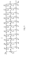
- Fig. 1 illustrates a sampling rate converting apparatus capable of converting the sampling frequency in two opposing directions (that is, capable of reversibly converting the same between a first and a second sampling frequencies).
- the frequency ratio of first and second frequencies f 1 and f 2 of a digital signal, the sampling ratio of which must be converted is set to 4:3.
- the sampling frequency can reversibly be converted in a direction from digital signal S 2 composed of the first sampling frequency f 1 toward digital signal S 2 composed of the second sampling frequency f 2 or in the reverse direction of the above-described direction.
- the sampling rate converting apparatus 1 is constituted by an oversampling filter arranged to have a value which is the least common multiple of the sampling frequencies f 1 and f 2 of the first and the second digital signals S 1 and S 2 .
- the sampling rate converting apparatus 1 is constituted by a so-called FIR (finite impulse response) type digital filter to which the first digital signal S 1 is, as input digital signal DIN, supplied when the sampling frequency f 1 of the first digital signal S 1 is rate-converted into the second sampling frequency f 2 to obtain the second digital signal S 2 .
- FIR finite impulse response
- the input digital signal DIN and output digital signals D 1 to D 11 from the corresponding flip-flops 2A to 2K are respectively supplied to weighting means composed of 12 multiplying circuits 3A to 3L.
- the first, the fourth, the seventh and the tenth multiplying circuits 3A, 3D, 3G and 3J are respectively given predetermined coefficients c 0 , c 3 , c 6 and c 9
- the other multiplying circuits 3B, 3C, 3E, 3F, 3H, 3I, 3K and 3L are respectively given coefficients c 1 , c 2 , c 4 , c 5 , c 7 , c 8 , c 10 and c 11 the value of each of which is "0".
- the input digital signal DIN supplied to the first, the fourth, the seventh and the tenth multiplying circuits 3A, 3D, 3G and 3J and the output digital signals D 3 , D 6 and D 9 from the third, the sixth and the ninth flip-flops 2C, 2F and 2I are respectively multiplied by the predetermined coefficients c 0 , c 3 , c 6 and c 9 . Then, the results of all of the multiplications are added to one another by using adder circuits 4A to 4K.
- the input digital signal DIN can be oversampled at an oversampling frequency of 3f 1 which is three times the first sampling frequency f 1 and as well as it can be resampled at a frequency which is 1/4 of the same. Therefore, the second digital signal S 2 composed of the second sampling frequency f 2 can be transmitted as output digital signal D OUT .
- the second digital signal S 2 is supplied as the input digital signal D IN .
- the first, the fifth and the ninth multiplying circuits 3A, 3E and 3I are respectively given predetermined coefficients c 0 , c 4 and c 8
- the other multiplying circuits 3B, 3C, 3D, 3F, 3G, 3H, 3J, 3K and 3L are respectively given coefficients c 1 , c 2 , c 3 , c 5 , c 6 , c 7 , c 9 , c 10 and c 11 the value of each of which is "0".
- the input digital signal DIN supplied to the first, the fifth and the ninth multiplying circuits 3A, 3E and 3I and the output digital signals D 4 and D 8 from the fourth and the eighth flip-flops 2D and 2H are respectively multiplied by the predetermined coefficients c 0 , c 4 and c 8 .
- the results of all of the multiplications are added to one another by using adder circuits 4A to 4K.
- the input digital signal D IN can be oversampled at an oversampling frequency of 4f 2 which is four times the second sampling frequency f 2 and as well as it can be resampled at a frequency which is 1/3 of the same. Therefore, the first digital signal S 1 composed of the first sampling frequency f 1 can be transmitted as output digital signal D OUT .
- the oversampling frequency has a relationship of a least common multiple of the first and the second sampling frequencies f 1 and f 2 . Therefore, in both cases where the rate is converted from the first sampling frequency f 1 into the second sampling frequency f 2 and where the rate is converted from the second sampling frequency f 2 into the first sampling frequency f 1 , the sampling rate converting apparatus is, as shown in Fig. 2, able to have the same Nyquist characteristics T NQ at the Nyquist frequencies (f 1 /2 and f 2 /2) which are required in the corresponding cases.
- the above-described structure is arranged in such a manner that the FIR type digital filters 2A to 2K, 3A to 3L and 4A to 4K which correspond to the least common multiple of the first and the second sampling frequencies f 1 and f 2 are used to perform the rate conversions in accordance with the oversampling method. Therefore, the sampling rate converting apparatus 1 capable of converting the rate in two opposing directions between the first and the second sampling frequencies f 1 and f 2 can be realized.
- the sampling rate converting apparatus rate-converts the sampling frequency of a 625/50 component digital video signal formed in accordance with the D-1 format into a sampling frequency which corresponds to a PAL composite digital video signal formed in accordance with the D-2 format. Furthermore, it rate-converts the sampling frequency of the PAL composite digital video signal into a sampling frequency which corresponds to the 625/50 component digital video signal.
- sampling frequency fD1 of the 625/50 component digital video signal formed in accordance with the D-1 format relative to the sampling frequency fD2 of the PAL composite digital video signal formed in accordance with the D-2 format is such that a conventional approach to sample rate conversion might require a disadvantageous large filter, e.g. 16500 order.
- the sample rate converting apparatus is arranged in such a manner that an oversampling filter of a length of, for example 4554-order may be used for converting in both directions.
- sampling frequency of the PAL composite digital video signal is converted into a frequency which corresponds to the 625/50 component digital video signal
- the oversampling frequencies become frequencies of 6381 [MHz] and 7342.04 [MHz]. Therefore, a result can be obtained in that the Nyquist characteristics realized due to the oversampling frequency generate a practically sufficiently small difference of about 7 [%].
- the sampling rate converting apparatus is arranged to have the Nyquist frequency set to a frequency with which no problem takes place practically.
- the rate of the sampling frequency can reliably be converted in the two opposing directions between the 625/50 component digital video signal and the PAL composite digital video signal while further simplifying its structure.
- reference numeral 10 represents the overall body of a sampling rate converting apparatus for converting the sampling rate in the two opposing directions between the 625/50 component digital video signal and the PAL composite digital video signal in accordance with the above-described principle. According to this embodiment it is formed by combining four oversampling filters 11 (11A, 11B, 11C and 11D) each of which is formed into an integrated circuit.
- each of the oversampling filters 11 are, as shown in Fig. 4, be constituted by the FIR type digital filter the length of which is 5-order or shorter.
- Digital signal DGIN supplied through a first input terminal 11a thereof is, via a delay input selection circuit 12, supplied to a series circuit comprising the first, the second, the third and the fourth flip-flops 13A, 13B, 13C and 13D each of which has predetermined delay time T 1 .
- the delay input selection circuit 12 has flip-flops 12A, 12B and 12C respectively having delay time T 1 , delay time 2T 1 which is two times the former, and delay time 3T 1 which is three times the same. Therefore, the digital signal DG IN is delayed by each of predetermined time periods when it passes through the flip-flops 12A, 12B and 12C. Then, delay outputs are respectively supplied to a first, a second and a third input terminals a, b and c of a switch circuit 12D.
- a selection from the first to the third input terminals a to c is made in accordance with selection control signal CNT 1 supplied to a filter control circuit 14.
- the input digital signal DG IN is delayed by a delay time in accordance with the control operation performed by the filter control circuit 14.
- Delay digital signal DG 10 obtained as a result of this is transmitted to the ensuing first flip-flop 13A and is as well as supplied to the first multiplying circuit 15A.
- delay digital signals DG 11 , DG 12 and DG 13 respectively transmitted from the first, the second and the third flip-flop 13A, 13B and 13C are transmitted to the ensuing second, the third and the fourth flip-flops 13B, 13C and 13D and as well as are supplied to a second, a third and a fourth multiplying circuits 15B, 15C and 15D.
- Delay digital signal DG 14 transmitted from the fourth flip-flop 13D is transmitted via a first output terminal llb as output delay digital signal DD OUT of the overall body of the oversampling filter 11. Furthermore, it is supplied to a first input terminal a of a delay quantity selection circuit 16.
- the delay digital signal DG 13 transmitted from the third flip-flop 13C is also supplied to a flip-flop 13E the delay time of which is 3T 1 , which is three times the delay time of the above-described flip-flop 13D, as well as supplied to this flip-flop 13D.
- Delay digital signal DG 15 is supplied to a second input terminal b of the delay quantity selection circuit 16.
- the delay quantity selection circuit 16 selects the first input terminal a or the second input terminal b in response to second selection-control signal CNT 2 supplied from the filter circuit 14.
- second selection-control signal CNT 2 supplied from the filter circuit 14.
- the above-described multiplying circuits 15A to 15E are respectively supplied with coefficient data c 20 , c 21 , c 22 , c 23 and c 24 from first to fifth coefficient generating circuits 17A to 17E each of which is formed into a ROM (read only memory).
- the delay digital signals DG 10 , D 11 , DG 12 , DG 13 and DG 14 (or DG 15 ) and the corresponding coefficient data c 20 , c 21 , c 22 , c 23 and c 24 are multiplied together.
- the results of the multiplications are supplied to the input terminals a of a first to a fifth addition input selection circuits 18A to 18E before they are supplied to first to fifth adder circuits 19A to 19E via their output terminals.
- a second input terminal b of each of the first to the fifth addition input selection circuits 18A to 18E is grounded.
- first input terminals a of the first to the fifth addition input selection circuits 18A to 18E are selected in response to third selection control signal CNT 3 supplied from the filter control circuit 14, addition digital data DA IN supplied from outside through a second input terminal 11c and results of multiplications supplied from the first to the fifth multiplying circuits 15A to 15E are fully added to one another.
- the results of this are, as output digital signal DG OUT , transmitted through a second output terminal 11d.
- coefficient data c 20 to c 24 each of which is composed of 506 coefficients are stored in the storage region of the ROM of each of the first to the fifth coefficient generating circuits 17A to 17E. Each of the coefficients are arranged to be selected and transmitted at the predetermined delay time T 1 .
- ROM mode data DT ROM for instructing the read region of the ROMs of the coefficient generating circuits 17A to 17E in accordance with the operational mode and address data DT ADR for instructing the reading timing of the ROM in response to clock signals are supplied to the filter circuit 14 and address generating circuits 20A to 20E.
- the address generating circuits 20A to 20E generate read address data ADR 0 to ADR 4 which correspond to ROM mode data DT ROM and address data DT ADR so as to supply them to the first to the fifth coefficient generating circuits 17A to 17E.
- coefficient data c 20 to c 24 written in the coefficient generating circuits 17A to 17E are read in accordance with read address data ADR 0 to ADR 4 supplied from the corresponding address generating circuits 20A to 20E.
- the filter control circuit 14 detects the operation mode which denotes how to control the overall body of the oversampling filter 11 in accordance with ROM mode data DT ROM , address data DT ADR and control data DT CNT which has been set and supplied.
- the filter control circuit 14 generates first, second and third selection control signals CNT 1 , CNT 2 and CNT 3 which respectively control the delay input selection circuit 12, the delay quantity selection circuit 16 and the first to the fifth addition input selection circuits 18A to 18E.
- the operation mode for the overall body of the oversampling filter 11 can be controlled.
- the bidirectional sampling rate converting apparatus constituted by the four oversampling filters 11 each of which is, as shown in Fig. 4, formed into an integrated circuit. Then, the overall structure will be described.
- the first and the second oversampling filters 11A and 11B are longitudinally connected to each other and the third and the fourth oversampling filters 11C and 11D are connected in the same manner.
- digital signal S IN10 which is the subject of the sampling rate conversion, is, as the input digital signal DG IN , supplied to the first input terminals 11a of the first and the third oversampling filters 11A and 11C.
- the second input terminals llc of the first and the third oversampling filters 11A and 11C are grounded. As a result, the value "0" is supplied to each of them as the addition digital data DA IN .
- the output terminals 11b of the first and the third oversampling filters 11A and 11C are respectively connected to the first input terminals 11a of the second and the fourth oversampling filters 11B and 11D. Therefore, output delay digital signal DG OUTA and DG OUTC transmitted from the first and the third oversampling filters 11A and 11C are supplied as input digital signal DG IN for the second and the fourth oversampling filters 11B and 11D.
- output terminals 11d of the first and the third oversampling filters 11A and 11C are respectively connected to the second input terminals 11b of the second and the fourth oversampling filters 11B and 11D.
- output digital signals DG OUTA and DG OUTC transmitted from the first and the third oversampling filters 11A and 11C are supplied as addition digital data DA IN for the second and the fourth oversampling filters 11B and 11D.
- the longitudinally connected first and the second oversampling filters 11A and 11B and the third and the fourth oversampling filters 11C and 11D, as a whole, constitute the oversampling filter which is composed of the FIR type digital filter and the length of which is 4554-order.
- output digital signals DG OUTB and DG OUTD transmitted from the second and the fourth oversampling filters 11B and llD are supplied to an adder circuit 21.
- an additional signal thus-obtained is transmitted as digital signal SOUT10 after the rate has been converted.
- the sampling rate converting apparatus 10 is able to selectively convert the sampling rate from input data in the D-1 format into output data in the D-2 format and as well as from input data in the D-2 format into output data in the D-1 format.
- the basic structure of the oversampling filter for performing the rate conversion operation employs the portion constituted by longitudinally connecting the upper two oversampling filters 11A and 11B shown in Fig. 3 when the rate conversion from the D-1 format to the D-2 format is performed.
- the rate conversion from the D-2 format to the D-1 format is performed, a structure constituted by connecting all of the oversampling filters 11A to 11D is employed.
- the above-described structures are switched over in response to the selection control signals CNT 1 , CNT 2 and CNT 3 formed in the above-described filter control circuit 14.
- reference numeral 30 represents, by an equivalent circuit, the overall body of the sampling rate converting apparatus for use when the rate of the sampling frequency of the 625/50 component digital video signal formed in accordance with the D-1 format is, by using the above-described bidirectional sampling rate converting apparatus 10 (refer to Fig. 3), converted into a sampling frequency which corresponds to the PAL composite digital video signal formed in accordance with the D-2 format.
- the first input terminal a of the switch circuit 12D of each delay input selection circuit 12 of the longitudinally-connected first and the second oversampling filters 11A and 11B is selected in response to the first selection control signal CNTi transmitted from the filter control circuit 14.
- the first input terminal a of each of the delay quantity selection circuits 16 is selected in response to the second selection control signal CNT 2 transmitted from the filter circuit 14. Furthermore, the first input terminal a of each of the first to the fifth addition input selection circuits 18A to 18E is selected in response to the third selection control signal CNT 3 transmitted from the filter circuit 14.
- the second input terminal b of each of the first to the fifth addition input selection circuits 18A to 18E of the longitudinally connected the third and the fourth oversampling filters 11C and 11D is selected in response to the third selection control signal CNT 3 transmitted from the filter control circuit 14.
- the sampling rate converting apparatus 30 is constituted by the FIR type digital filter which controls the third and the fourth oversampling filters 11C and 11D in such a manner that they are not operated, which uses the first and the second oversampling filters llA and 11B and the length of which is 9 orders (since the final stage multiplication is not performed as described later, the length is 9 orders although the circuit is structured by 10 orders).
- the transmitted 625/50 component digital video signal S IND1 is sequentially supplied to 10 flip-flops 31A to 31J each of which has the predetermined delay time T 1 .
- Output digital signals D 30 to D 39 from the flip-flops 31A to 31I are supplied to ensuing flip-flops 31B to 31J.
- output digital signals D 30 to D 39 from the flip-flops 31A to 31J are multiplied by predetermined coefficients C 30 to C 39 in multiplying circuits 32A to 32J before the all of the results of the multiplications are added in adder circuits 33A to 33J.
- the sampling frequency of the 625/50 component digital video signal S IND1 is rate-converted so that digital signal S OUTD2 which corresponds to the sampling frequency of the PAL composite digital video signal is obtained.
- the coefficient c 39 supplied to the final multiplying circuit 32J is determined to be a value of "0", while the other coefficients c 30 to c 38 supplied to the other multiplying circuits 32A to 32I use the coefficient data c 20 to c 24 composed of 506 coefficients and stored in the ROM region of each of the coefficient generating circuits 17A to 17E (refer to Fig. 4) of the first and the second oversampling filters 11A and 11B at every predetermined delay time t 1 .
- the 625/50 component digital video signal S IND1 is oversampled at a frequency which is 506 times its frequency. Furthermore, it can be resampled at a frequency of 1/414 times of it by supplying a predetermined coefficient which is generated at the timing of the frequency which is 1/414 times the above-described oversampling frequency.
- the sampling rate converting apparatus 30 constitutes a 4554-order (9 orders x 506 times) oversampling filter capable of oversampling the input 625/50 component digital video signal S IND1 at a frequency which is 506 times its frequency and resampling the above-described oversampling frequency at a frequency which is 1/414 times the oversampling frequency.
- the sampling rate converting apparatus 30 can be realized with which the digital signal S OUTD2 which correspond to the sampling frequency of the PAL composite digital video signal can be obtained by rate-converting the sampling frequency of the 625/50 component digital video signal S IND1 .
- reference numeral 40 represents, by an equivalent circuit, the overall body of the sampling rate converting apparatus for use when the rate of the sampling frequency of the PAL composite digital video signal formed in accordance with the D-2 format is, by using the above-described bidirectional sampling rate converting apparatus 10 (refer to Fig. 3), converted into a sampling frequency which corresponds to the 625/50 component digital video signal formed in accordance with the D-1 format.
- a first input terminal a of the switch circuit 12D of the delay input selection circuit 12 of the first oversampling filter llA is, as shown in Figs. 3 and 4, selected in response to the first selection control signal CNT 1 transmitted from the filter control circuit 14.
- the first or the second input terminal a or b of the delay quantity selection circuit 16 is switched over at a predetermined timing which corresponds to the second selection control signal CNT 2 .
- the third input terminal c of the switch circuit 12D of the delay input selection circuit 12 of the second oversampling filter 11B is selected in response to the first selection control signal CNT 1 transmitted from the filter circuit 14. Furthermore, the first input terminal a of the delay quantity selection circuit 16 is selected in response to the second selection control signal CNT 2 .
- the second input terminal b of the switch circuit 12D of the delay input selection circuit 12 of the third oversampling filter 11C is selected in response to the first selection control signal CNT 1 transmitted from the filter control circuit 14.
- the first input terminal a of the delay quantity selection circuit 16 is selected in response to the second selection control signal CNT 2 .
- the first input terminal a of the switch circuit 12D of the delay input selection circuit 12 of the fourth oversampling filter 11D is selected in response to the first selection control signal CNT 1 transmitted from the filter control circuit 14.
- the first input terminal a of the delay quantity selection circuit 16 is selected in response to the second selection control signal CNT 2 .
- the first input terminals a of the first to the fifth addition input selection circuits 18A to 18E of the first to the fourth oversampling filters 11A to 11D are selected in response to the selection control signal CNT 3 transmitted from each of the filter control circuits 14.
- the sampling rate converting apparatus 40 operates the third and the fourth oversampling filters 11C and 11D at timing which is delayed by the predetermined delay time T 1 with respect to the first and the second oversampling filters 11A and 11B. Furthermore, it adds the digital outputs from them so that a 11-order FIR type digital filter is, as the whole, constituted.
- the PAL composite digital video signal S IND2 is, in an equivalent manner, supplied to the longitudinally-connected circuits respectively composed of 10 flip-flops 41A to 41J and 44A to 44J.
- Each of the flip-flops 41A to 41J has the predetermined delay time T 1 and the output digital signals D 40 to D 49 from the corresponding flip-flops 41A to 41J are supplied to the ensuing flip-flops 41B to 41J.
- the output signals D 40 to D 49 from the corresponding flip-flops 41A to 41J are multiplied with predetermined coefficients c 40 to c 49 in multiplying circuits 42A to 42J before they are added to one another in the adder circuits 43A to 43J.
- the results of the additions are supplied to the adder circuit 21.
- the output digital signal D 44 to be supplied to a fifth multiplying circuit 42E is selected from an output digital signal D 44A transmitted from a fifth flip-flop 41E by the delay quantity selection circuit 16 or the output digital signal D 44B of a first flip-flop 41K so as to be supplied.
- the output digital signal D 44A transmitted from the fifth flip-flop 41E is delayed from the output digital signal D 43 transmitted from the fourth flip-flop 41D by the predetermined delay time T 1 .
- Output digital signal D 44B from an eleventh flip-flop 41K is delayed from the output digital signal D 44A transmitted from the fifth flip-flop 41E by delay time 2T 1 which is two times that of the output digital signal D 44A .
- the first flip-flop 44A of the flip-flops 44A to 44J has the delay time 2T 1 which is the two times those of others flip-flops. Furthermore, each of the second to the tenth flip-flops 44B to 44J has the predetermined time T 1 .
- output digital signals D 50 to D 59 from the corresponding flip-flops 44A to 44J are supplied to the ensuing flip-flops 44B to 44J.
- the output digital signals D 50 to D 59 from the corresponding flip-flops 44A to 44J are multiplied with predetermined coefficients c 50 to c 59 in multiplying circuits 45A to 45J before they are added to one another in adder circuits 46A to 46J.
- the results of the additions are supplied to the adder circuit 21.
- the sampling frequency of the PAL composite digital video signal S IND2 is rate-converted so that the digital signal S OUTD1 having a sampling frequency which corresponds to the 625/50 component digital video signal is obtained.
- the coefficients c 40 to c 49 to be supplied to the upper multiplying circuits 42A to 42J comprise data c 20 to c 24 for 506 coefficients stored in the ROM regions of the coefficient generating circuits 17A to 17E (refer to Fig. 4) of the first and the second oversampling filters 11A and 11B at predetermined delay time T 1 .
- the similar structures of the coefficient generating circuits 17A to 17E of the first and the second oversampling filters 11A and 11B are used when the rate conversion from the D-1 format to the D-2 format is performed.
- the coefficients respectively allocated to the multiplying circuits 42A to 42J are arranged as follows: as the coefficient c4o to be supplied to the first multiplying circuit 42A, 414 coefficients from the 0-th to 413-th coefficients in the coefficient data c 20 for 506 coefficients are supplied, while the 414-th to the 505-th coefficients are not supplied but a value of "0" is supplied as an alternative to this.
- All of the coefficients c 49 to be supplied to the tenth multiplying circuit 42J are determined to be a value of "0".
- the coefficient data c 20 to c 24 for 506 coefficients stored in the ROM regions of the coefficient generating circuits 17A to 17E of the third to the fourth oversampling filters 11C and 11D at every predetermined delay time T 1 are respectively supplied.
- the coefficients to be supplied to each of the multiplying circuits 45A to 45J are as follows:
- All of the coefficients c 59 to be supplied to the tenth multiplying circuit 42J are determined to a value of "0".
- each of coefficient data and the flip-flop outputs which are multiplied by each of the multiplying circuits 42A to 42J and 45A to 45J, must be considered.
- the reason for this lies in that a deviation takes place between coefficient data and sampling data transferred by the flip-flop because the 506 coefficients stored in each of the coefficient generating circuits are used to rate-convert the D-1 format into the D-2 format and to rate-convert both the D-2 format into the D-1 format.
- the above-described deviation can be corrected by the oversampling FIR filter of the invention aligning the phase of sampling data to coefficient data.
- the lower oversampling filter is given the delay time of 2T 1 in the delay input selection circuit 12 as the delay time for its leading flip-flop 44A.
- the above-described lower oversampling filter multiplies sampling data delayed by 1 clock by coefficient data c 50 to c 59 .
- the multiplying circuits 42A to 42D of the upper oversampling filter as it is multiply input sampling data by coefficient data c 40 to c 43 .
- the multiplying circuit 42E must perform the multiplications of the 0-th to the 45-th coefficients and perform multiplications of data obtained by delaying sampling data used in the above-described multiplications by 2 clocks by the 460-th to 505-th coefficients. Therefore, the timing of sampling data supplied to the multiplying circuit 42E is delayed by the delay time T 1 or 3T 1 in the delay quantity selection circuit 16 before it is multiplied by coefficient c 44 .
- Coefficient data c 45 to c 49 are deviated by 2 clocks from sampling data. Therefore, a further delay time of 2T 1 is given in the delay input selection circuit 12. It corresponds to the flip-flop 41F.
- the oversampling filter is arranged in such a manner that coefficient data for 506 coefficients are combined in units of 414 coefficients to supply them to the multiplying circuits 42A to 42J and 45A to 45J as coefficient data c 40 to c 49 and c 50 to c 59 every determined time T 1 . Therefore, as a whole, the 4554-order (11-order x 414 times) oversampling filter is constituted which is capable of oversampling the supplied PAL composition digital video signal S IND2 at a frequency which is 414 times its frequency and as well as resampling it at a frequency which is 1/506 times the oversampling frequency.
- the sampling rate converting apparatus 40 can be realized which is capable of obtaining the digital signal S OUTD1 which corresponds to the sampling frequency of the 625/50 component digital video signal by rate-converting the sampling frequency of the PAL composite digital video signal S IND2 .
- the oversampling filters formed into the FIR type digital filters each of which is able to select the coefficient to be supplied to the multiplying circuit are combined to one another so as to supply the predetermined coefficient to each of the oversampling filters in accordance with the sampling rate conversion direction between the 625/50 component digital video signal and the PAL composite digital video signal.
- a bidirectional sampling rate converting apparatus can be realized which is capable of converting the sampling frequency of the 625/50 component digital video signal into the sampling frequency which corresponds to the PAL composite digital video signal and as well as capable of converting the sampling frequency of the PAL composite digital video signal into the sampling frequency which corresponds to the 625/50 component digital video signal.
- the above-described first example is arranged in such a manner that the frequency ratio of the sampling frequencies of the digital signals which are the subject of the rate conversion is determined to be 3:4 and the sampling rate is converted in the two opposing directions by using the oversampling filter the length of which is 12 orders.
- a similar effect to that obtainable from the above-described first example can be obtained in a case where the frequency ratio or the sampling frequencies has a simple integer proportional relationship by arranging the structure in such a manner that a sampling filter the length of which corresponds to the least common multiple of the frequency ratio is constituted.
- the oversampling filter the length of which is 4554 orders is used for approximation from the relationship of the frequency ratio of the sampling frequency of the 625/50 component digital video signal and the sampling frequency of the PAL composite digital video signal so that the sampling rate is converted in the two opposing directions.
- the technique can be applied widely when the sampling rate is converted between the sampling frequency of a variety of digital signals and other sampling frequencies in the two opposing directions.
- the length of the oversampling filter may be determined in accordance with this.
- the sampling rate converting apparatus is constituted by combining four FIR type digital filters each of which is formed into an integrated circuit and the length of each which is five orders.
- sampling rate converting apparatus A variety of structures can be employed to form the sampling rate converting apparatus. For example, a structure which is arranged in such a manner that the overall body is formed into an integrated circuit can be employed. In this case, a similar effect can be obtained to that obtainable from the above-described modes.
Landscapes
- Engineering & Computer Science (AREA)
- Physics & Mathematics (AREA)
- Computer Hardware Design (AREA)
- Mathematical Physics (AREA)
- Multimedia (AREA)
- Signal Processing (AREA)
- Compression, Expansion, Code Conversion, And Decoders (AREA)
- Television Systems (AREA)
- Transmission Systems Not Characterized By The Medium Used For Transmission (AREA)
Claims (2)
- Appareil de conversion de cadence d'échantillonnage pour convertir un signal numérique qui est échantillonné par une première ou une seconde fréquence d'échantillonnage dans ladite seconde ou ladite première fréquence d'échantillonnage, dont le rapport de fréquence vérifie une relation intégrale simple, à ladite première ou à ladite seconde fréquence d'échantillonnage, ledit appareil de conversion de cadence d'échantillonnage comprenant :caractérisé pardes filtres de sur-échantillonnage composés de filtres numériques du type FIR dont la longueur correspond au plus petit multiple commun dudit rapport de fréquence de ladite première et de ladite seconde fréquences d'échantillonnage, oùladite première ou ladite seconde fréquence d'échantillonnage dudit signal numérique est convertie dans ladite seconde ou ladite première fréquence d'échantillonnage, lesdits filtres de sur-échantillonnage comprenant :un premier filtre à réponse impulsionnelle finie (41A à K, 42A à J, 43A à J) ; etun second filtre à réponse impulsionnelle finie (44A à J, 45A à J, 46A à J) monté en parallèle avec ledit premier filtre à réponse impulsionnelle finie ;
un moyen à retard (16, 41E, 41K) pour faire varier le retard entre des étages de filtre dudit premier filtre à réponse impulsionnelle finie. - Appareil de conversion de cadence d'échantillonnage selon la revendication 1, dans lequel chacun dudit premier filtre à réponse impulsionnelle finie et dudit second filtre à réponse impulsionnelle finie comprend une pluralité d'étages de filtre, chaque étage de filtre comprenant une bascule (13A à E) pour maintenir et retarder une valeur d'échantillon, un multiplieur (15A à E) pour multiplier ladite valeur d'échantillon par une valeur de coefficient (C20 à C24) pour former une sortie de multiplieur, un commutateur pour sélectionner comme sortie de commutation soit ladite sortie de multiplieur soit une valeur nulle en fonction du signal de commande (CNT3), et un additionneur pour former une sortie d'étage en additionnant ladite sortie de commutation à une sortie d'étage d'un étage précédent voisin quelconque.
Applications Claiming Priority (3)
| Application Number | Priority Date | Filing Date | Title |
|---|---|---|---|
| JP2035614A JPH10294646A (ja) | 1990-02-16 | 1990-02-16 | サンプリングレート変換装置 |
| JP35614/90 | 1990-02-16 | ||
| PCT/JP1991/000175 WO1991012664A1 (fr) | 1990-02-16 | 1991-02-14 | Appareil de conversion de la cadence d'echantillonnage |
Publications (3)
| Publication Number | Publication Date |
|---|---|
| EP0469159A1 EP0469159A1 (fr) | 1992-02-05 |
| EP0469159A4 EP0469159A4 (en) | 1992-05-06 |
| EP0469159B1 true EP0469159B1 (fr) | 1998-01-07 |
Family
ID=12446724
Family Applications (1)
| Application Number | Title | Priority Date | Filing Date |
|---|---|---|---|
| EP91904463A Expired - Lifetime EP0469159B1 (fr) | 1990-02-16 | 1991-02-14 | Appareil de conversion de la cadence d'echantillonnage |
Country Status (6)
| Country | Link |
|---|---|
| US (1) | US5204827A (fr) |
| EP (1) | EP0469159B1 (fr) |
| JP (1) | JPH10294646A (fr) |
| KR (1) | KR920702085A (fr) |
| DE (1) | DE69128570T2 (fr) |
| WO (1) | WO1991012664A1 (fr) |
Families Citing this family (42)
| Publication number | Priority date | Publication date | Assignee | Title |
|---|---|---|---|---|
| GB9205614D0 (en) * | 1992-03-14 | 1992-04-29 | Innovision Ltd | Sample rate converter suitable for converting between digital video formats |
| US5561616A (en) * | 1992-08-13 | 1996-10-01 | Tektronix, Inc. | Fir filter based upon squaring |
| US5331346A (en) * | 1992-10-07 | 1994-07-19 | Panasonic Technologies, Inc. | Approximating sample rate conversion system |
| US5274372A (en) * | 1992-10-23 | 1993-12-28 | Tektronix, Inc. | Sampling rate conversion using polyphase filters with interpolation |
| US5717617A (en) * | 1993-04-16 | 1998-02-10 | Harris Corporation | Rate change filter and method |
| US5963160A (en) * | 1993-09-13 | 1999-10-05 | Analog Devices, Inc. | Analog to digital conversion using nonuniform sample rates |
| EP0719477A1 (fr) * | 1993-09-13 | 1996-07-03 | Analog Devices, Inc. | Conversion analogique-numerique avec des frequences d'echantillonnage non uniformes |
| US5619202A (en) * | 1994-11-22 | 1997-04-08 | Analog Devices, Inc. | Variable sample rate ADC |
| EP0719478B1 (fr) * | 1993-09-13 | 1998-07-22 | Analog Devices, Inc. | Conversion numerique-analogique avec des frequences d'echantillonnage non uniformes |
| US5892468A (en) * | 1993-09-13 | 1999-04-06 | Analog Devices, Inc. | Digital-to-digital conversion using nonuniform sample rates |
| US5712635A (en) * | 1993-09-13 | 1998-01-27 | Analog Devices Inc | Digital to analog conversion using nonuniform sample rates |
| US5625358A (en) * | 1993-09-13 | 1997-04-29 | Analog Devices, Inc. | Digital phase-locked loop utilizing a high order sigma-delta modulator |
| US5574454A (en) * | 1993-09-13 | 1996-11-12 | Analog Devices, Inc. | Digital phase-locked loop utilizing a high order sigma-delta modulator |
| US5512897A (en) * | 1995-03-15 | 1996-04-30 | Analog Devices, Inc. | Variable sample rate DAC |
| US5732002A (en) * | 1995-05-23 | 1998-03-24 | Analog Devices, Inc. | Multi-rate IIR decimation and interpolation filters |
| US5638010A (en) * | 1995-06-07 | 1997-06-10 | Analog Devices, Inc. | Digitally controlled oscillator for a phase-locked loop providing a residue signal for use in continuously variable interpolation and decimation filters |
| US6473732B1 (en) * | 1995-10-18 | 2002-10-29 | Motorola, Inc. | Signal analyzer and method thereof |
| US6058404A (en) * | 1997-04-11 | 2000-05-02 | Texas Instruments Incorporated | Apparatus and method for a class of IIR/FIR filters |
| CA2207670A1 (fr) * | 1997-05-29 | 1998-11-29 | Andre Marguinaud | Procede de synthese d'un filtre numerique a reponse impulsionnelle finie et filtre obtenu selon le procede |
| US5903480A (en) * | 1997-09-29 | 1999-05-11 | Neomagic | Division-free phase-shift for digital-audio special effects |
| JPH11331992A (ja) * | 1998-05-15 | 1999-11-30 | Sony Corp | デジタル処理回路と、これを使用したヘッドホン装置およびスピーカ装置 |
| EP0957579A1 (fr) | 1998-05-15 | 1999-11-17 | Deutsche Thomson-Brandt Gmbh | Procédé et dispositif pour la conversion de taux d'échantillonage de signaux audio |
| US6057789A (en) * | 1998-10-29 | 2000-05-02 | Neomagic Corp. | Re-synchronization of independently-clocked audio streams by dynamically switching among 3 ratios for sampling-rate-conversion |
| US6252919B1 (en) | 1998-12-17 | 2001-06-26 | Neomagic Corp. | Re-synchronization of independently-clocked audio streams by fading-in with a fractional sample over multiple periods for sample-rate conversion |
| US6591283B1 (en) * | 1998-12-24 | 2003-07-08 | Stmicroelectronics N.V. | Efficient interpolator for high speed timing recovery |
| US6553398B2 (en) * | 2000-09-20 | 2003-04-22 | Santel Networks, Inc. | Analog fir filter with parallel interleaved architecture |
| DE10334064B3 (de) * | 2003-07-25 | 2005-04-14 | Infineon Technologies Ag | Verfahren und Schaltungsanordnung zum Kalibrieren eines den Abtastzeitpunkt eines Empfangssignals beeinflussenden Abtastungssteuersignales eines Abtastphasenauswahlelements |
| KR100834937B1 (ko) | 2006-07-14 | 2008-06-03 | 엠텍비젼 주식회사 | 특정 샘플링 레이트를 목적으로 하는 샘플링 레이트 변환방법 및 샘플링 레이트 변환 시스템 |
| US8958571B2 (en) | 2011-06-03 | 2015-02-17 | Cirrus Logic, Inc. | MIC covering detection in personal audio devices |
| US9824677B2 (en) | 2011-06-03 | 2017-11-21 | Cirrus Logic, Inc. | Bandlimiting anti-noise in personal audio devices having adaptive noise cancellation (ANC) |
| US9318094B2 (en) | 2011-06-03 | 2016-04-19 | Cirrus Logic, Inc. | Adaptive noise canceling architecture for a personal audio device |
| US9123321B2 (en) | 2012-05-10 | 2015-09-01 | Cirrus Logic, Inc. | Sequenced adaptation of anti-noise generator response and secondary path response in an adaptive noise canceling system |
| US9318090B2 (en) | 2012-05-10 | 2016-04-19 | Cirrus Logic, Inc. | Downlink tone detection and adaptation of a secondary path response model in an adaptive noise canceling system |
| US9532139B1 (en) | 2012-09-14 | 2016-12-27 | Cirrus Logic, Inc. | Dual-microphone frequency amplitude response self-calibration |
| US9414150B2 (en) | 2013-03-14 | 2016-08-09 | Cirrus Logic, Inc. | Low-latency multi-driver adaptive noise canceling (ANC) system for a personal audio device |
| US10219071B2 (en) | 2013-12-10 | 2019-02-26 | Cirrus Logic, Inc. | Systems and methods for bandlimiting anti-noise in personal audio devices having adaptive noise cancellation |
| US9478212B1 (en) | 2014-09-03 | 2016-10-25 | Cirrus Logic, Inc. | Systems and methods for use of adaptive secondary path estimate to control equalization in an audio device |
| US20160365084A1 (en) * | 2015-06-09 | 2016-12-15 | Cirrus Logic International Semiconductor Ltd. | Hybrid finite impulse response filter |
| US20170054510A1 (en) * | 2015-08-17 | 2017-02-23 | Multiphy Ltd. | Electro-optical finite impulse response transmit filter |
| US10026388B2 (en) | 2015-08-20 | 2018-07-17 | Cirrus Logic, Inc. | Feedback adaptive noise cancellation (ANC) controller and method having a feedback response partially provided by a fixed-response filter |
| US10013966B2 (en) | 2016-03-15 | 2018-07-03 | Cirrus Logic, Inc. | Systems and methods for adaptive active noise cancellation for multiple-driver personal audio device |
| US11522525B2 (en) * | 2020-05-28 | 2022-12-06 | Raytheon Company | Reconfigurable gallium nitride (GaN) rotating coefficients FIR filter for co-site interference mitigation |
Family Cites Families (10)
| Publication number | Priority date | Publication date | Assignee | Title |
|---|---|---|---|---|
| NL168669C (nl) * | 1974-09-16 | 1982-04-16 | Philips Nv | Interpolerend digitaal filter met ingangsbuffer. |
| US4020332A (en) * | 1975-09-24 | 1977-04-26 | Bell Telephone Laboratories, Incorporated | Interpolation-decimation circuit for increasing or decreasing digital sampling frequency |
| JPS58141025A (ja) * | 1982-02-16 | 1983-08-22 | Mitsubishi Electric Corp | 信号処理回路 |
| NL8202687A (nl) * | 1982-07-05 | 1984-02-01 | Philips Nv | Decimerende filterinrichting. |
| NL8400073A (nl) * | 1984-01-10 | 1985-08-01 | Philips Nv | Interpolerende filterinrichting met niet-rationale verhouding tussen de ingangs- en uitgangsbemonsterfrequentie. |
| GB2180114A (en) * | 1985-04-13 | 1987-03-18 | Plessey Co Plc | Digital filters |
| DE3605927A1 (de) * | 1986-02-25 | 1987-08-27 | Standard Elektrik Lorenz Ag | Digitaler interpolator |
| JPH0731875B2 (ja) * | 1987-05-15 | 1995-04-10 | 株式会社日立製作所 | デイジタルオ−デイオレコ−ダ |
| JPH0793548B2 (ja) * | 1987-08-31 | 1995-10-09 | 三洋電機株式会社 | 標本化周波数変換回路 |
| DE3888830T2 (de) * | 1988-08-30 | 1994-11-24 | Ibm | Massnahmen zur Verbesserung des Verfahrens und Vorrichtung eines digitalen Frequenzumsetzungsfilters. |
-
1990
- 1990-02-16 JP JP2035614A patent/JPH10294646A/ja active Pending
-
1991
- 1991-02-14 EP EP91904463A patent/EP0469159B1/fr not_active Expired - Lifetime
- 1991-02-14 US US07/768,243 patent/US5204827A/en not_active Expired - Lifetime
- 1991-02-14 WO PCT/JP1991/000175 patent/WO1991012664A1/fr active IP Right Grant
- 1991-02-14 KR KR1019910701315A patent/KR920702085A/ko not_active Application Discontinuation
- 1991-02-14 DE DE69128570T patent/DE69128570T2/de not_active Expired - Fee Related
Also Published As
| Publication number | Publication date |
|---|---|
| US5204827A (en) | 1993-04-20 |
| JPH10294646A (ja) | 1998-11-04 |
| WO1991012664A1 (fr) | 1991-08-22 |
| EP0469159A1 (fr) | 1992-02-05 |
| DE69128570D1 (de) | 1998-02-12 |
| EP0469159A4 (en) | 1992-05-06 |
| DE69128570T2 (de) | 1998-05-07 |
| KR920702085A (ko) | 1992-08-12 |
Similar Documents
| Publication | Publication Date | Title |
|---|---|---|
| EP0469159B1 (fr) | Appareil de conversion de la cadence d'echantillonnage | |
| EP0137464B1 (fr) | Appareil numérique de traitement de signaux comprenant un filtre numérique | |
| US6041339A (en) | Efficient decimation filtering | |
| JP3297165B2 (ja) | 標本化周波数変換器 | |
| US4709343A (en) | Variable-passband variable-phase digital filter | |
| EP0305864B1 (fr) | Convertisseur de fréquence d'échantillonnage et méthode pour convertir une fréquence d'échantillonnage plus basse vers une fréquence d'échantillonnage plus haute | |
| JPH0340972B2 (fr) | ||
| US5717617A (en) | Rate change filter and method | |
| JPH09135149A (ja) | 広帯域デジタルろ波方法およびこの方法を使用したフィルタ | |
| US5528527A (en) | Sampling frequency converter | |
| JPH0828649B2 (ja) | ディジタルフィルタ | |
| GB2303009A (en) | Finite impulse response filter | |
| EP0882326B1 (fr) | Methode de decimation et filtre de decimation | |
| US5317529A (en) | Digital filter using intermediate holding registers and common accumulators and multipliers | |
| EP0608664B1 (fr) | Méthode pour filtrer des signaux numériques à haute résolution et architecture correspondante d'un filtre numérique | |
| EP0608665B1 (fr) | Méthode de filtrage des signaux numériques à haute résolution et architecture correspondante de filtre numérique | |
| EP0576215B1 (fr) | Convertisseur de fréquence d'échantillonnage pour convertir le débit de données | |
| JPH05327409A (ja) | レート変換方法及びその変換回路 | |
| JPH10126645A (ja) | 周波数変換装置 | |
| JP2929807B2 (ja) | ディジタルフィルタ | |
| JP2002368582A (ja) | インターポーレータ | |
| EP1458097A1 (fr) | Conversion arbitraire de taux d' échantillonage | |
| JP2628506B2 (ja) | ディジタルフィルタ | |
| JP3258938B2 (ja) | デシメーションフィルタ | |
| JPH0640616B2 (ja) | デイジタルフイルタ−周波数特性変換装置 |
Legal Events
| Date | Code | Title | Description |
|---|---|---|---|
| PUAI | Public reference made under article 153(3) epc to a published international application that has entered the european phase |
Free format text: ORIGINAL CODE: 0009012 |
|
| 17P | Request for examination filed |
Effective date: 19911029 |
|
| AK | Designated contracting states |
Kind code of ref document: A1 Designated state(s): DE FR GB |
|
| A4 | Supplementary search report drawn up and despatched |
Effective date: 19920316 |
|
| AK | Designated contracting states |
Kind code of ref document: A4 Designated state(s): DE FR GB |
|
| 17Q | First examination report despatched |
Effective date: 19941129 |
|
| GRAG | Despatch of communication of intention to grant |
Free format text: ORIGINAL CODE: EPIDOS AGRA |
|
| GRAG | Despatch of communication of intention to grant |
Free format text: ORIGINAL CODE: EPIDOS AGRA |
|
| GRAG | Despatch of communication of intention to grant |
Free format text: ORIGINAL CODE: EPIDOS AGRA |
|
| GRAH | Despatch of communication of intention to grant a patent |
Free format text: ORIGINAL CODE: EPIDOS IGRA |
|
| GRAH | Despatch of communication of intention to grant a patent |
Free format text: ORIGINAL CODE: EPIDOS IGRA |
|
| GRAA | (expected) grant |
Free format text: ORIGINAL CODE: 0009210 |
|
| AK | Designated contracting states |
Kind code of ref document: B1 Designated state(s): DE FR GB |
|
| REF | Corresponds to: |
Ref document number: 69128570 Country of ref document: DE Date of ref document: 19980212 |
|
| ET | Fr: translation filed | ||
| PLBE | No opposition filed within time limit |
Free format text: ORIGINAL CODE: 0009261 |
|
| STAA | Information on the status of an ep patent application or granted ep patent |
Free format text: STATUS: NO OPPOSITION FILED WITHIN TIME LIMIT |
|
| 26N | No opposition filed | ||
| REG | Reference to a national code |
Ref country code: GB Ref legal event code: IF02 |
|
| PGFP | Annual fee paid to national office [announced via postgrant information from national office to epo] |
Ref country code: FR Payment date: 20050208 Year of fee payment: 15 |
|
| PGFP | Annual fee paid to national office [announced via postgrant information from national office to epo] |
Ref country code: GB Payment date: 20050209 Year of fee payment: 15 |
|
| PGFP | Annual fee paid to national office [announced via postgrant information from national office to epo] |
Ref country code: DE Payment date: 20050210 Year of fee payment: 15 |
|
| PG25 | Lapsed in a contracting state [announced via postgrant information from national office to epo] |
Ref country code: GB Free format text: LAPSE BECAUSE OF NON-PAYMENT OF DUE FEES Effective date: 20060214 |
|
| PG25 | Lapsed in a contracting state [announced via postgrant information from national office to epo] |
Ref country code: DE Free format text: LAPSE BECAUSE OF NON-PAYMENT OF DUE FEES Effective date: 20060901 |
|
| GBPC | Gb: european patent ceased through non-payment of renewal fee |
Effective date: 20060214 |
|
| REG | Reference to a national code |
Ref country code: FR Ref legal event code: ST Effective date: 20061031 |
|
| PG25 | Lapsed in a contracting state [announced via postgrant information from national office to epo] |
Ref country code: FR Free format text: LAPSE BECAUSE OF NON-PAYMENT OF DUE FEES Effective date: 20060228 |