EP0467983B1 - Diebstahlsicherung - Google Patents
Diebstahlsicherung Download PDFInfo
- Publication number
- EP0467983B1 EP0467983B1 EP90907144A EP90907144A EP0467983B1 EP 0467983 B1 EP0467983 B1 EP 0467983B1 EP 90907144 A EP90907144 A EP 90907144A EP 90907144 A EP90907144 A EP 90907144A EP 0467983 B1 EP0467983 B1 EP 0467983B1
- Authority
- EP
- European Patent Office
- Prior art keywords
- theft device
- male
- casing
- elongate
- closure member
- Prior art date
- Legal status (The legal status is an assumption and is not a legal conclusion. Google has not performed a legal analysis and makes no representation as to the accuracy of the status listed.)
- Expired - Lifetime
Links
- 230000002093 peripheral effect Effects 0.000 claims abstract description 25
- 239000012530 fluid Substances 0.000 claims description 16
- 230000000717 retained effect Effects 0.000 claims description 4
- 238000012544 monitoring process Methods 0.000 claims description 3
- 239000003973 paint Substances 0.000 claims description 2
- 229910000831 Steel Inorganic materials 0.000 description 4
- 230000005540 biological transmission Effects 0.000 description 4
- 239000000523 sample Substances 0.000 description 4
- 239000010959 steel Substances 0.000 description 4
- 239000007789 gas Substances 0.000 description 3
- 239000007788 liquid Substances 0.000 description 3
- 238000000926 separation method Methods 0.000 description 3
- 239000000470 constituent Substances 0.000 description 2
- 238000010438 heat treatment Methods 0.000 description 2
- 239000002184 metal Substances 0.000 description 2
- 238000010008 shearing Methods 0.000 description 2
- 230000000007 visual effect Effects 0.000 description 2
- 230000002747 voluntary effect Effects 0.000 description 2
- 239000004593 Epoxy Substances 0.000 description 1
- 229910000760 Hardened steel Inorganic materials 0.000 description 1
- 238000002788 crimping Methods 0.000 description 1
- 239000011888 foil Substances 0.000 description 1
- 238000009413 insulation Methods 0.000 description 1
- 239000000314 lubricant Substances 0.000 description 1
- 239000000463 material Substances 0.000 description 1
- 210000000056 organ Anatomy 0.000 description 1
- IMACFCSSMIZSPP-UHFFFAOYSA-N phenacyl chloride Chemical compound ClCC(=O)C1=CC=CC=C1 IMACFCSSMIZSPP-UHFFFAOYSA-N 0.000 description 1
- 239000003491 tear gas Substances 0.000 description 1
Images



Classifications
-
- F—MECHANICAL ENGINEERING; LIGHTING; HEATING; WEAPONS; BLASTING
- F16—ENGINEERING ELEMENTS AND UNITS; GENERAL MEASURES FOR PRODUCING AND MAINTAINING EFFECTIVE FUNCTIONING OF MACHINES OR INSTALLATIONS; THERMAL INSULATION IN GENERAL
- F16G—BELTS, CABLES, OR ROPES, PREDOMINANTLY USED FOR DRIVING PURPOSES; CHAINS; FITTINGS PREDOMINANTLY USED THEREFOR
- F16G13/00—Chains
-
- E—FIXED CONSTRUCTIONS
- E05—LOCKS; KEYS; WINDOW OR DOOR FITTINGS; SAFES
- E05B—LOCKS; ACCESSORIES THEREFOR; HANDCUFFS
- E05B45/00—Alarm locks
- E05B45/005—Chain-locks, cable-locks or padlocks with alarms
-
- E—FIXED CONSTRUCTIONS
- E05—LOCKS; KEYS; WINDOW OR DOOR FITTINGS; SAFES
- E05B—LOCKS; ACCESSORIES THEREFOR; HANDCUFFS
- E05B67/00—Padlocks; Details thereof
- E05B67/003—Chain, wire or cable locks
-
- F—MECHANICAL ENGINEERING; LIGHTING; HEATING; WEAPONS; BLASTING
- F16—ENGINEERING ELEMENTS AND UNITS; GENERAL MEASURES FOR PRODUCING AND MAINTAINING EFFECTIVE FUNCTIONING OF MACHINES OR INSTALLATIONS; THERMAL INSULATION IN GENERAL
- F16G—BELTS, CABLES, OR ROPES, PREDOMINANTLY USED FOR DRIVING PURPOSES; CHAINS; FITTINGS PREDOMINANTLY USED THEREFOR
- F16G13/00—Chains
- F16G13/02—Driving-chains
- F16G13/10—Driving-chains with universal joints
Definitions
- the present invention relates to an anti-theft device, and in particular an anti-theft device of the type comprising an elongated assembly which is relatively flexible and deformable and which is capable of forming a loop and which has at one of its ends a male closure member and at its other end.
- a female closing member adapted to receive and lock the male closing member
- these closing members comprising a closing device which can be opened by means of a key to release the other closing member
- elongated assembly consisting of elongated elements fitted and assembled one inside the other in a non-removable manner in the manner of a chain, at least part of one being capable of having a predetermined angular deviation from the corresponding part of the other to form a loop, each elongated element comprising at one of its ends a female part, and at its end opposite mite a male part.
- This device comprises a cable on which are sleeves fitted into one another. These sockets are made of surface treated steel and have a surface hardness such that they cannot be attacked by conventional cutting tools.
- these devices can be opened by means of a crowbar: it suffices to place said bar substantially in the axis of the loop formed by the cable and to rotate the bar around a perpendicular axis. to it so that twist the cable first in the form of an 8, then in the form of a twist: one thus arrives, by tightening the twist sufficiently, to develop in the cable tensile stresses such that the strands of the latter disengage from the locking members attached to the ends of the cable, the cable remaining intact.
- the object of the present invention is to remedy the drawbacks of known anti-theft devices and to propose an anti-theft device of the aforementioned type which resists attack by cutting, shearing, sawing, cutting, which is simple and convenient to use, relatively inexpensive, and which cannot be opened by twisting on itself by means of a crowbar.
- the anti-theft device is characterized in that, in the assembled state, the male part successively presents from its end, peripheral retaining means for connecting in an undeniable manner the elongate element to an adjacent elongate element , and peripheral groove means separated from the retaining means and limited on the side opposite to them by a shoulder, in that said male part passes through in the assembled state an opening which limits on one side a female part with which said male part cooperates, the shoulder of which does not cross the opening and abuts against an edge thereof, and in that the edges of the opening and the means forming peripheral groove are shaped so beautifully that said male part is adapted to pivot by a predetermined angle relative to said female part, and that, when the device is closed on itself to form a loop, radial parts opposite of the walls of the opening cooperate with the corresponding parts of the walls of the means forming a peripheral groove and bear directly on these walls to resist the efforts of separation of the elongated elements from one another.
- the device of the invention thus does not comprise any cable, the fixing of which on the locking members situated at its respective ends would constitute a weak point of the device in the event of an attempt to break in by torsion.
- the possible limited angular difference between two adjacent elongated elements limits the deformability of the anti-theft device and prevents any attempt to twist it.
- the present invention makes it possible to simply solve the problem. posed above.
- the resistance to torsional forces by the support of the walls of the opening on the means forming a peripheral groove is independent of the means of assembling the elongated elements. in the other, these assembly means generally constituting the weak points of known anti-theft devices. It is thus possible to obtain simply and reliably the high levels of torsional strength required by the regulations in force.
- the elongated assembly is housed inside a flexible tube mounted in leaktight manner on the ends of said elongated assembly and containing a pressurized fluid
- the closure member comprises means for receive and control the pressure of the fluid inside the tube and detect that this pressure has reached a predetermined minimum value, and autonomous means for trigger an alarm when the pressure has reached this predetermined minimum value
- the anti-theft device comprises an alarm block separate from the closure member, which comprises means for sending a signal to the alarm block when the fluid pressure has reaches said predetermined minimum value, this signal being for example a radio signal.
- the anti-theft device comprises an element forming a cover for access to the autonomous radio means; this element is electrically isolated from at least part of the rest of the closure member and is electrically connected to an interior antenna of said radio means to serve as an exterior antenna.
- the anti-theft device comprises an elongated relatively flexible and deformable assembly 1, substantially in the form of a chain, which is capable of forming a loop.
- the chain 1 has at one of its ends a male closing member 2 and at its other end a female closing member 3 adapted to receive and lock the male closing member 2.
- the female member is a spherical casing 3 composed of two hemispherical parts assembled in any way; the housing contains a lock 4 which can be opened by means of a key 5.
- the bolt 6 of the lock fits into a groove 7 of the male element 2 to lock the latter and block the anti-theft device in the closed position.
- the chain 1 consists of elongated elements 8 forming substantially cylindrical links and in one piece, fitted and snapped into each other in a non-removable manner, and articulated with respect to each other.
- the links 8 are made for example of heat treatment steel having after treatment a surface hardness such that they cannot be attacked with pliers, with shears or with a saw: they are for example made of 16 NC 6 hardened steel and case-hardened.
- each link 8 comprises at one of its ends a female part 9 and at its opposite end a male head 10 intended to fit and snap into the female part 9 of a link 8 adajcent.
- the end of the female part 9 is closed by a wall 11 comprising a circular axial opening 12 intended to receive the male head 10 of an adjacent link 8.
- Behind the wall 11 extends a cylindrical cavity 13 whose internal diameter is larger than that of the opening 12.
- the male head 10 has on its peripheral wall, the outside diameter of which is slightly smaller than the inside diameter of the opening 12, a groove 14 which receives a rod 15.
- the rod 15 completely enters the groove 14 to allow passage of the head 10 in the opening 12, then relaxes in the cavity 13 and prevents any withdrawal of the head 10.
- the peripheral wall 20 between the groove 16 and the cylindrical body 17 of the mailpiece 8 is preferably spherical in shape, and the same is true of the surface of the external radial edge 21 of the wall 11.
- the rod 15 has been shown with a circular section, but may have another section, in particular rectangular or trapezoidal.
- the chain 1 is inserted inside a flexible tube 22, mounted in leaktight manner on the end links 23 and 24, and filled with a fluid under pressure, by example a liquid and possibly gas such as air to create pressure.
- a fluid under pressure by example a liquid and possibly gas such as air to create pressure.
- the pressure can also be created by the elasticity of the tube 22.
- the liquid can be an indelible dye to mark the aggressor, and / or a lubricant facilitating the movements of the links relative to each other;
- the gas can also be a tear gas.
- the anti-theft device comprises, as shown in FIG. 1, the means necessary to receive and control the pressure of the fluid inside the tube 22 and to detect that this pressure has reached a minimum value predetermined, and means for triggering an alarm when the pressure has reached this predetermined minimum value.
- the housing 3 also includes a battery 28 and an audible warning 29 such as a horn powered by the battery 28 when the switch 27 is closed.
- the electrical circuit can also include a switch 30 closed by the male end 2 of the chain 1 when the anti-theft device is closed and locked.
- the end link 24 is permanently fixed to the housing 1, for example by a nut 31 which is then locked.
- the inside of the link 24 is hollow and constitutes a cylinder inside which is housed a piston 32 which is biased on the housing side 3 by a spring 33 and on the chain side 1 by the pressure of the fluid contained inside the flexible tube 22 tightly attached to the link 24.
- the end link 23 on the free male end side 2 of the chain 1 enters a tube 34 of the housing 3 and is blocked by the bolt 6 of the lock 4 which is inserted in the groove 7 .
- the closure member 35 into which the end link 24 is snapped in 36, comprises a movable piston 37 which receives the pressure of the fluid on one side and the spring force 33 on the other.
- the piston 37 and the closing member 35 comprise means known in themselves for transmitting a radio alarm signal, symbolized at 39, indicating an attempted break-in.
- This radio signal 39 is received by a receiver unit 40 separate from the closure member 35 and comprising circuits known in themselves intended to receive the radio signal 39 and to actuate a horn (not shown).
- the housing 40 can thus be concealed on the vehicle or the equipment that it is desired to protect, and be only difficult to access so as not to risk being neutralized.
- each link 41 comprises two distinct parts articulated with respect to each other: on the one hand a substantially tubular casing 42 has at one of its ends a tapered part 43 which has an axial opening 44 of inner diameter smaller than the inner diameter of the tubular part 45; on the other hand, a spindle 46 comprises a cylindrical body 47 intended to pass through the axial opening 44, and a head 48 intended to penetrate into the tubular part 45 and to be retained by the tapered part 43 of the casing 42.
- Each link 41 further comprises a tubular sleeve 49 intended to be threaded onto the cylindrical body 47 of the spindle 46 and to be inserted inside the tubular part 45 of the casing 42 of an adjacent link 41, as well as latching means for securing the sleeve 49 and the pin 46 on the one hand, the sleeve 49 and the casing 42 of a link 41 adjacent on the other hand.
- the head 48 of the spindle 46 has a surface outer 50 spherical, and the inner wall 51 of the tapered portion 43 of the casing 42 has a spherical inner surface combined with said outer surface 50.
- the tapered portion 43 of the casing 42 has a spherical outer surface 52 concentric with its inner surface 51, and the wall of the casing 42 has, at the non-tapered end thereof, a spherical inner surface 53 conjugate with the surface outer spherical 52 of the casing 42.
- the sleeve 49 has in its peripheral part a groove 54 in which a rod 55 can disappear when the sleeve 49 is inserted inside the envelope 42 of a link 41 adjacent.
- the rod 55 relaxes when the groove 54 arrives at the level of a conjugate groove 56 formed in the inner peripheral wall of said envelope: the sleeve 49 is then snapped into a fixed position inside the envelope 42.
- the cylindrical body 47 of the spindle 46 has, near its end opposite to the head 48, a groove 57 in which a rod 58 can completely disappear to allow the body 47 to pass inside the socket 49.
- the groove 57 arrives at the end of the sleeve 49, so that the rod 58 relaxes and blocks the pin 46 relative to the sleeve 49.
- This assembly is non-removable and tamper-proof: the part of the cylindrical body 47 visible between the head 48 and the head-end 48 of the sleeve 49 constitutes a groove which receives the edge of the opening 44 when two adjacent links make an angle to each other.
- the adjacent links 41 are therefore nested one inside the other practically without play. Thanks to the aforementioned spherical bearings, the casing 42 of a link 41 is articulated by ball joint both relative to the head of the spindle 46 associated with it and relative to the envelope 42 of the adjacent link. To allow these ball-and-socket joints to function, the wall of the sleeve 49 at the end of the latter located on the side of the head 48 of the associated pin 46 is indented at 59 so as to extend the interior spherical surface 53.
- peripheral wall 60 of the axial opening 44 of the tapered portion 43 is in the form of a truncated cone flared outward to allow an angular separation between the envelope 42 of a link 41 and the pin 46 of the latter retained in the envelope of an adjacent link.
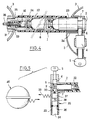
- the chain (not shown) formed by the links 41 is inserted into a flexible tube 22; the flexible tube 22 is tightly fixed to the periphery of the end link 61 which is permanently snapped into a female closing member 62 by a rod 63; the tube 22 is also tightly fixed to the periphery of the end piece 64 which constitutes the free end of the chain.
- the tube 22 is filled with a pressurized fluid, and the anti-theft device comprises means for receiving and controlling the pressure of the fluid inside the tube and detecting that this pressure has reached a predetermined minimum value, and means for triggering an alarm when the pressure has reached this predetermined minimum value.
- the end piece 64 has a tubular structure for this purpose, and comprises substantially in its middle a transverse wall 65 fixed to the peripheral wall of the end piece 64 by a pin 66.
- a piston 67 is pushed by the pressure of the fluid against the wall 65 against the action of a spring 68, and has at its periphery a seal 69 to contain the fluid.
- the piston 67 also includes a finger 70 which moves in a longitudinal housing 71 of the wall of the end piece 64 if the piston 67 moves inside the end piece 64 under the action of the spring 68 when the pressure of the fluid drops inside the tube 22, either during an assault attempt, or as a result of fluid leakage: when the pressure has reached a predetermined minimum threshold, the finger actuates the feeler 72, which protrudes slightly inside the housing 71, a micro-contact 73.
- the microswitch 73 is enclosed inside a housing 74 made of insulating, independent, removable and interchangeable material.
- This box includes all the elements making it possible, when actuating the probe 72, to emit a radio alarm signal; it thus comprises in particular, and in a manner known per se, a battery 75, a wired printed circuit with its components (not shown), a light-emitting diode for monitoring 76, an internal antenna 77.
- the housing 74 is covered by a removable cover 78 which fits tightly on the closing member 62.
- the cover 78 shown in particular in FIG. 10, is U-shaped: its branches 79 and 80 each have an opening, respectively 81, 82, crossed by the end piece 64 when the anti-theft device is in the locked closed position shown in FIGS. 7 to 9: the cover 78 is thus retained on the closing member 62. It is also fixed to the latter by two screws 83. Its base 92 fits into the cavity 93 formed between the side walls of the member 62 to protect the housing 74 (see Figure 8).
- the cover 78 serves as an outdoor radio antenna. It is for this purpose isolated from the general mass of the closure member 62: this insulation is simply done by a layer of Epoxy paint, and the contact between the internal antenna 77 and this external antenna 78 is ensured by an elastic foil 84 pressure mounted against the cover 78 on a small surface remaining conductive.
- the closing member 62 comprises a closing piston 85, the rounded end of which is pushed by a spring 86 towards the inside of the opening of the member 62 which receives the end piece 64.
- the closing piston 85 is shown in Figures 7 and 8 in solid lines in its closed position and in dashes in its open position 85 '.
- the end piece 64 has at its free end a tapered conical surface 87 which has the purpose of lifting the closing piston 85 when the anti-theft device is closed: it can therefore be closed without the key; when the end piece 64 is in place, the closing piston 85 falls into a radial opening 88 of the end piece 64 and locks the latter (position in solid lines).
- the conical part 87 of the end piece 64 protrudes from the outer wall of the branch 80 of the cover 78 to lock the latter when the anti-theft device is closed.
- the opening 82 of the branch 80 of the cover 78 has, on the side of the base 92 of the cover, a flat 94.
- This flat 94 corresponds to a conjugate flat 95 at the end of the end piece 64 and is used for centering this end-piece: the end-piece being thus centered, the radial bore 88 is automatically presented in front of the closing piston 85, the housing 71 is automatically presented in front of the probe 72.
- the end piece 64 also has at its end a lock barrel (not shown) operable with a key.
- the barrel when the key makes a U-turn on itself, actuates a finger 89 which rotates 180 ° around the axis of the nozzle 64: in this movement, the finger 89 lifts radially, in the direction of the piston 85, a pusher 90 which has a groove 91 in which the finger 89 slides.
- the pusher 90 pushes the closing piston 85 back into its position 85 'shown in dashes, which enables the endpiece 64 to be removed from the member 62.
- the links 41, the closure member 62, the cover 78, are preferably made of a heat treatment steel, for example of 16 NC 6 steel, hardened and case-hardened.
- the envelopes of the links 41 have, for example, a thickness of approximately 4 mm, an external diameter of approximately 24 mm, a length of approximately 35 mm, which corresponds after nesting to a pitch of approximately 30 mm between two adjacent envelopes.
- the maximum angular difference between two adjacent envelopes is 12 to 15 ° for example.
- an anti-theft device of length approximately 120 cm which, in the closed position, has a diameter of approximately 40 cm, and which resists the usual attacks by shearing, sawing, or by twisting, and which triggers an alarm as soon as the tube 22 has been pierced. It is obviously extremely easy to add any number of links on request when assembling the anti-theft device.
- the closing member 62 is associated with an alarm block, such as the block 40 in FIG. 5, of any known type, concealed in a place that is difficult to access from the vehicle or the equipment to be protect, this alarm unit being adapted to receive the radio signal emitted by the cover 78 and to supply all audible and visual alarm devices such as horn, flashing lights, etc.
- an alarm block such as the block 40 in FIG. 5, of any known type, concealed in a place that is difficult to access from the vehicle or the equipment to be protect, this alarm unit being adapted to receive the radio signal emitted by the cover 78 and to supply all audible and visual alarm devices such as horn, flashing lights, etc.
- the diode 76 lights up when the user engages the end piece 64 in the opening of the closing member 62.
- the microswitch 73 is actuated by its feeler 72 pushed back by the end piece 64, and energizes the radio transmitter.
- the diode 76 lights up, which makes it possible to check the electronic system, the contact of the micro-contact 73, the state of the battery 75, that of the diode 76, the proper functioning of the radio transmission to the receiver 40
- the closing piston 85 which has been lifted by the inlet cone 87 of the end piece 64 falls into the bore 88 and locks the assembly. There is no need for a key to close the lock.
- the probe 72 of the microswitch 73 falls into the housing 71 and cuts through the contact 73 the electronics of the radio transmitter which from this moment no longer consumes energy.
- the pressure of the oil in the tube 22 keeps the piston 67 in mechanical abutment against the wall 65 while compressing its return spring 68.
- the radio transmission is preferably on the frequency of 303.875 MHz, approved in many countries, but can also be on other approved frequencies, such as approximately 224 MHz.
- the transmission is obviously coded to avoid untimely interference, in particular the voluntary switching on of the system by a transmitter of the same frequency.
- the radio receiver of the alarm unit 40 is also coded and adjusted to the frequency of the transmitter.
- the latching means described can be replaced by other equivalent means, such as for example crimping, by pushing inward the metal of the casing which enters the socket and the metal of the socket which penetrates for example a peripheral groove of the spindle.
- the locking systems described can be replaced by other equivalents ensuring the same functions and producing the same results. It is also possible to modify the distribution of the constituent elements between the free end piece, on the one hand, the closing member on the other hand.
- the anti-theft device described can also be used without the alarm devices described, whether they are in one piece with the anti-theft device or separate from it.
- the anti-theft device described is provided equipped with a standardized lock of the "alarm" type, imperceptible and inviolable. It can of course be fitted with a lock of any type, and in particular be suitable for a so-called electronic lock of any type: it would suffice to introduce a smart card into a slot in the closing member. coded read by a reader contained in this organ. The pusher could then be driven by an electric micromotor; the battery supplying this motor could for example be housed either in the closing member, or in a handle integral with the smart card.
- the anti-theft device according to the invention can also be used without tube 22, without pressure switch and without alarm, the device being limited to the assembly of the links equipped respectively at its ends with a female closing member and a male end piece. .
Landscapes
- Engineering & Computer Science (AREA)
- General Engineering & Computer Science (AREA)
- Mechanical Engineering (AREA)
- Burglar Alarm Systems (AREA)
- Materials For Medical Uses (AREA)
- Air Bags (AREA)
- External Artificial Organs (AREA)
- Orthopedics, Nursing, And Contraception (AREA)
- Lock And Its Accessories (AREA)
Claims (14)
- Diebstahlsicherungsvorrichtung mit einer relativ nachgiebigen und verformbaren, länglichen Anordnung (1), die zum Bilden einer Schlinge geeignet ist und an einem ihrer Enden ein männliches Verschlußorgan (2, 64) und an seinem anderen Ende ein weibliches Verschlußorgan (3, 62) hat, das dazu ausgelegt ist, das männliche Verschlußorgan (2, 64) aufzunehmen und zu verriegeln, wobei eines der Verschlußorgane (3, 62; 2, 64) eine Verschlußvorrichtung umfaßt, die mittels eines Schlüssels zum Freigeben des anderen Verschlußorgans geöffnet werden kann, wobei die längliche Anordnung (1) aus länglichen Elementen (8, 41) besteht, die ineinander gepaßt und in unlösbarer Art miteinander nach Art einer Kette verbunden sind, wobei ein Teil von zumindest einem Element dazu geeignet ist, um einen vorbestimmten Winkel in bezug auf das entsprechende Teil des anderen Elements zur Bildung einer Schlinge verschwenkt zu werden, wobei jedes längliche Element (8, 41) an einem seiner Enden einen weiblichen Teil (9, 42) und an seinem gegenüberliegenden Ende einen männlichen Teil (10; 46, 49) umfaßt, dadurch gekennzeichnet, daß der männliche Teil (10; 46, 49) im zusammengesetzten Zustand ausgehend von seinem Ende, aufeinanderfolgend eine am Umfang angeordnete Rückhalteeinrichtung (14, 15; 54, 55) zum unlösbaren Verbinden des länglichen Elements (8, 41) mit einem benachbarten länglichen Element (8, 41) und eine eine Umfangsrille bildende Einrichtung (16; 49, 47, 50) umfaßt, die von der Rückhalteeinrichtung (14, 15; 54, 55) getrennt und von der Seite begrenzt ist, die ihr in Gestalt einer Schulter (20, 50) gegenüberliegt, daß der männliche Teil (10; 46, 49) im zusammengesetzten Zustand eine Öffnung (12, 44) durchsetzt, die eine Seite eines weiblichen Teils (9, 42) begrenzt, mit dem der männliche Teil (10; 46, 49) zusammenwirkt, dessen Schulter (20, 50) die Öffnung (12, 44) nicht durchsetzt und gegen deren Rand (21, 51) daran anstößt, und daß die Ränder der Öffnung (12, 44) und die die Umfangsrille bildende Einrichtung (16; 49, 47, 50) derart formmäßig aneinander angepaßt sind, daß der männliche Teil (10; 46, 49) um einen vorbestimmten Winkel in bezug auf den weiblichen Teil (9, 42) zu verschwenken vermag, und daß dann, wenn die Vorrichtung zur Bildung einer Schlinge in sich selbst geschlossen ist, die den Wänden (18, 21; 60, 51) der Öffnung (12, 44) radial gegenüberliegenden Bereiche mit den entsprechenden Bereichen der Wände (19, 20; 47, 50) der die Umfangsrille bildenden Einrichtung (16; 49, 47, 50) zusammenwirken und sich direkt auf diesen Wänden (19, 20; 47, 50) abstützen, um Einwirkungen zur Trennung der länglichen Elemente (8, 41) voneinander zu widerstehen.
- Diebstahlsicherungsvorrichtung nach Anspruch 1, dadurch gekennzeichnet, daß die länglichen Elemente (8, 41) in bezug auf ihre Längsachse drehsymmetrisch sind.
- Diebstahlsicherungsvorrichtung nach Anspruch 1 oder 2, dadurch gekennzeichnet, daß jedes längliche Element (8) ein einstückiges Element ist, daß das Ende des weiblichen Teils (9) durch eine Wand (11) verschlossen ist, die eine im wesentlichen kreisförmige axiale Öffnung (12) umfaßt, die dazu bestimmt ist, den männlichen Teil (10) eines benachbarten länglichen Elements (8) aufzunehmen, und daß sich hinter der Wand (11) ein im wesentlichen kreisförmiger Hohlraum (13) erstreckt, dessen Durchmesser größer ist als derjenige der Öffnung (12), in der sich eine elastische Sperreinrichtung oder eine elastisch angebrachte Einrichtung (15) des männlichen Teils (10) entspannen kann, die dazu geeignet ist, vollständig in eine Umfangsrille (14) der Außenumfangswand dieses Teils einzurücken, um in die Öffnung (12) einzutreten, und, sobald sie einmal entspannt ist, das Herausziehen des männlichen Teils (10) zu verhindern.
- Diebstahlsicherungsvorrichtung nach Anspruch 3, dadurch gekennzeichnet, daß der männliche Teil (10) hinter der Rille (14) eine zweite Umfangsrille (16) umfaßt, die zur Aufnahme des Innenrands der Öffnung (12) bestimmt ist, und daß der radiale Innenrand (18) der Wand (11) und der radiale Rand (19) auf der Seite des männlichen Endes der Umfangsrille (16) des männlichen Teils formmäßig derart aneinander angepaßt sind, daß sie sich aufeinander abstützen, wenn die längliche Anordnung (1) zur Bildung der Schlinge in sich selbst geschlossen ist.
- Diebstahlsicherungsvorrichtung nach Anspruch 1 oder 2, dadurch gekennzeichnet, daß jedes längliche Element (41) zwei unterschiedliche aneinander angelenkte Teile umfaßt, von denen einer eine im wesentlichen rohrförmige Hülse (42) ist, die an einem ihrer Enden einen verjüngten Bereich (43) umfaßt, der eine axiale Öffnung (44) mit einem Durchmesser hat, der kleiner ist als der Innendurchmesser des rohrförmigen Teils (45), wobei der andere einen Dorn (46) bildet, der einen zylindrischen Körper (47) umfaßt, der dazu bestimmt ist, in die axiale Öffnung (44) einzutreten, und einen Kopf (48), der dazu bestimmt ist, in den rohrförmigen Teil (45) einzudringen und in dem verjüngten Teil (43) der Hülse (42) zurückgehalten zu werden.
- Diebstahlsicherungsvorrichtung nach Anspruch 5, dadurch gekennzeichnet, daß das längliche Element (41) außerdem eine Buchse (49) umfaßt, die dazu bestimmt ist, auf den zylindrischen Körper (47) des Dorns (46) aufgeschoben zu werden und in das Innere des rohrförmigen Teils (45) der Hülse (42) eines benachbarten, länglichen Elements (41) eingeführt zu werden, sowie eine Einrichtung zum Zusammenschließen der Buchse (49) mit dem Dorn (46) einerseits und der Buchse (49) mit der Hülse (42) des benachbarten länglichen Elements (41) andererseits.
- Diebstahlsicherungsvorrichtung nach Anspruch 6, dadurch gekennzeichnet, daß der Kopf (48) des Dorns (46) eine kugelförmige Außenfläche (50) hat und mit der Innenwand (51) des verjüngten Bereichs (43) der Hülse (42) ein Kugelgelenk bildet.
- Diebstahlsicherungsvorrichtung nach Anspruch 7, dadurch gekennzeichnet, daß der verjüngte Bereich (43) der Hülse (42) eines Elements (41) eine Kugelaußenfläche (52) hat und mit der ihm gegenüberliegenden Seite des Rands (53) der Wand der Hülse (42) des benachbarten Elements (41) ein Kugelgelenk bildet.
- Diebstahlsicherungsvorrichtung nach Anspruch 8, dadurch gekennzeichnet, daß dann, wenn beide benachbarte, längliche Elemente (41) ineinander eingreifend miteinander verbunden sind, die Kugelaußenfläche (50) des Kopfs (48) des Dorns (46) des ersten Elements (41) im wesentlichen in Kontakt mit der Innenfläche (51) des verjüngten Bereichs (43) der Hülse (42) dieses Elements und die Kugelaußenfläche (52) der Hülse (42) des ersten Elements (41) im wesentlichen in Kontakt mit dem Rand (53) der Wand der Hülse (42) des zweiten Elements (41) steht, die ihm gegenüberliegt, wobei die beiden Kugelflächen (50) und (52) konzentrisch sind.
- Diebstahlsicherungsvorrichtung nach einem der Ansprüche 1 bis 9, dadurch gekennzeichnet, daß die längliche Anordnung (1) im Innern eines flexiblen Rohr (22) angeordnet ist, der auf den Enden der länglichen Anordnung (1) dicht angebracht ist und ein unter Druck stehendes Fluid enthält, wobei die Diebstahlsicherungsvorrichtung eine Einrichtung zum Erfassen und Steuern des Fluiddrucks im Innern des Rohrs (22) und zum Feststellen umfaßt, daß dieser Druck einen vorbestimmten minimalen Wert erreicht hat, und eine Einrichtung zum Auslösen eines Alarms, wenn der Druck diesen vorbestimmten minimalen Wert erreicht hat.
- Diebstahlsicherungsvorrichtung nach Anspruch 10, dadurch gekennzeichnet, daß sie ein Alarmgerät (40) getrennt vom Verschlußorgan (3, 62) umfaßt, das eine Einrichtung umfaßt, die an das Alarmgerät (40) ein Signal sendet, wenn der Fluiddruck den vorbestimmten minimalen Wert erreicht hat.
- Diebstahlsicherungsvorrichtung nach Anspruch 11, dadurch gekennzeichnet, daß die Einrichtung zum Senden eines Signals eine selbständige Einrichtung (74) zum Ausstrahlen eines elektromagnetischen Signals, beispielsweise eines Funksignals ist.
- Diebstahlsicherungsvorrichtung nach Anspruch 12, dadurch gekennzeichnet, daß sie ein eine Haube (78) bildendes Element für einen Zutritt zu der selbständigen Funkeinrichtung (74) umfaßt, und daß dieses Element (78) einerseits zumindest vom Rest des Verschlußorgans (62) elektrisch isoliert und andererseits elektrisch mit einer Innenantenne (77) der selbständigen Einrichtung (74) verbunden ist, die als Außenantenne dient.
- Diebstahlsicherungsvorrichtung nach Anspruch 13, dadurch gekennzeichnet, daß die Haube (78) vom Verschlußorgan (62) durch eine isolierende Anstrichschicht elektrisch isoliert ist.
Applications Claiming Priority (3)
| Application Number | Priority Date | Filing Date | Title |
|---|---|---|---|
| FR8904757 | 1989-04-11 | ||
| FR8904757A FR2645495B1 (fr) | 1989-04-11 | 1989-04-11 | Dispositif anti-effraction |
| PCT/FR1990/000256 WO1990012182A1 (fr) | 1989-04-11 | 1990-04-10 | Dispositif antivol |
Publications (2)
| Publication Number | Publication Date |
|---|---|
| EP0467983A1 EP0467983A1 (de) | 1992-01-29 |
| EP0467983B1 true EP0467983B1 (de) | 1994-10-05 |
Family
ID=9380592
Family Applications (1)
| Application Number | Title | Priority Date | Filing Date |
|---|---|---|---|
| EP90907144A Expired - Lifetime EP0467983B1 (de) | 1989-04-11 | 1990-04-10 | Diebstahlsicherung |
Country Status (7)
| Country | Link |
|---|---|
| US (1) | US5274353A (de) |
| EP (1) | EP0467983B1 (de) |
| AT (1) | ATE112604T1 (de) |
| AU (1) | AU5553090A (de) |
| DE (1) | DE69013148T2 (de) |
| FR (1) | FR2645495B1 (de) |
| WO (1) | WO1990012182A1 (de) |
Families Citing this family (35)
| Publication number | Priority date | Publication date | Assignee | Title |
|---|---|---|---|---|
| FR2660722A1 (fr) * | 1990-04-10 | 1991-10-11 | Bianchi Vittorio | Assemblage allonge du type chaine mecanique et utilisation d'un tel assemblage. |
| NL9300129A (nl) * | 1992-05-26 | 1993-12-16 | Johannes Ernest Leichel | Slot. |
| DE4230813C2 (de) * | 1992-09-15 | 1995-09-28 | Winkhaus Fa August | Bügelschloß |
| US5587702A (en) * | 1992-11-12 | 1996-12-24 | Chadfield; Garth R. | Padlock with tamper alarm |
| GB9317022D0 (en) * | 1993-08-16 | 1993-09-29 | Dynatec Ltd | Remote lock alarm |
| FR2723130B1 (fr) * | 1994-07-27 | 1996-10-18 | Vergez Jean Bernard | Cadenas a securite electrique |
| DE4430377A1 (de) * | 1994-08-26 | 1996-02-29 | Winkhaus Fa August | Sicherungseinrichtung für mobile Gegenstände, insbesondere Fahrräder |
| DE4434585C2 (de) * | 1994-09-28 | 1996-09-19 | Bremicker Soehne Kg A | Schloß |
| DE19601343A1 (de) * | 1996-01-16 | 1997-07-17 | Winkhaus Fa August | Schloßvorrichtung, insbesondere für Zweiradfahrzeuge |
| DE19714013B4 (de) * | 1997-04-04 | 2007-04-12 | Trelock Gmbh | Kabelschloß |
| JP3923175B2 (ja) * | 1998-04-28 | 2007-05-30 | 本田技研工業株式会社 | 自動二輪車の盗難防止装置 |
| DE10339259A1 (de) * | 2003-08-26 | 2005-03-24 | ABUS August Bremicker Söhne KG | Bügelschloß |
| US7053774B2 (en) | 2003-09-12 | 2006-05-30 | Alpha Security Products, Inc. | Alarming merchandise display system |
| US7385522B2 (en) | 2005-01-14 | 2008-06-10 | Invue Security Products Inc. | Portable alarming security device |
| US8429940B2 (en) * | 2005-04-19 | 2013-04-30 | Tyson Security Pty Limited | Armoured cable assemblies, locking assemblies, mounting systems and anchors |
| DE102007050163A1 (de) * | 2007-10-19 | 2009-04-23 | Katina Sostmann | Glied, Gliederkette und Tragesystem mit Gliederkette |
| ES2358973B1 (es) * | 2008-11-19 | 2011-12-27 | Fernando S. Colome Calafi | Disposición para antirrobos con alarma. |
| CN101852268B (zh) * | 2010-06-13 | 2012-09-05 | 上海通怡机械发展有限公司 | 万向免维护自调节球链 |
| EP2877659A4 (de) * | 2012-07-25 | 2016-04-13 | Master Lock Co | Integrierte antennenspule in einem metallischen körper |
| US9243428B1 (en) | 2014-12-12 | 2016-01-26 | Darrell Miracle | Bicycle lock |
| ES2597840B1 (es) * | 2015-07-21 | 2017-12-13 | Ride On Consulting, S.L. | Sistema de anclaje de bicicletas eléctricas |
| WO2017143093A1 (en) | 2016-02-16 | 2017-08-24 | Golock Technology, Inc. | Portable lock with integrity sensors |
| US11111699B2 (en) | 2016-03-04 | 2021-09-07 | SkunkLock, Inc. | Theft deterrent device and system |
| US9890561B2 (en) * | 2016-03-04 | 2018-02-13 | SkunkLock, Inc. | Pressurized chemical theft deterrent device |
| US10378246B2 (en) | 2016-03-04 | 2019-08-13 | SkunkLock, Inc. | Theft deterrent device and system |
| US10196837B2 (en) | 2016-09-01 | 2019-02-05 | Schlage Lock Company Llc | Ceramic spine security cable |
| DE102017105031A1 (de) | 2017-03-09 | 2018-09-13 | ABUS August Bremicker Söhne KG | Gelenkschloss mit Alarmeinrichtung |
| GB2569092B (en) * | 2017-10-09 | 2023-04-12 | John Howard Rawcliffe Nicholas | Hose security device |
| CN108400645B (zh) * | 2018-05-10 | 2024-01-12 | 锐华能源(大同)技术有限公司 | 一种直流输出的电动汽车直流充电模块 |
| US11513027B1 (en) | 2018-05-15 | 2022-11-29 | eWellbore, LLC | Triaxial leak criterion with thread shear for optimizing threaded connections in well tubulars |
| ES2733977B2 (es) * | 2018-05-30 | 2021-02-17 | Legutec Iniciativas Tecn S L | Dispositivo de seguridad configurable y procedimiento para su configuracion |
| EP3824154A4 (de) * | 2018-07-24 | 2022-04-27 | Skunklock, Inc. | Diebstahlabschreckungsvorrichtung und -system |
| US11434661B2 (en) * | 2018-11-13 | 2022-09-06 | Rivian Ip Holdings, Llc | Cable lock systems and methods |
| US12012167B2 (en) * | 2019-04-19 | 2024-06-18 | Lyft, Inc. | Apparatus, systems, and methods for rotating lock cables |
| GB2612004B (en) * | 2021-03-15 | 2025-04-23 | Zeal Innovation Ltd | Elongate body with exoskeleton |
Family Cites Families (7)
| Publication number | Priority date | Publication date | Assignee | Title |
|---|---|---|---|---|
| US1800943A (en) * | 1927-07-25 | 1931-04-14 | Junkunc John | Spare-tire lock |
| US3765196A (en) * | 1972-06-28 | 1973-10-16 | S Balicki | Armored cable-type lock assembly with special end fittings for the armored cable thereof |
| US3866205A (en) * | 1973-04-18 | 1975-02-11 | Louis B Payne | Locking device with alarm utilizing flexible gas impermeable tube |
| US4340007A (en) * | 1980-04-18 | 1982-07-20 | Paul Hogan | Portable locking and alarm system |
| NL8101261A (nl) * | 1981-03-16 | 1982-10-18 | Ronald Barend Van Santbrink | Kabelslot. |
| US4698620A (en) * | 1985-10-31 | 1987-10-06 | Marshall Steven G | Fluid-containing security device |
| US4920334A (en) * | 1989-04-24 | 1990-04-24 | Devolpi Dean R | Security system for bicycles, ski racks and coat racks |
-
1989
- 1989-04-11 FR FR8904757A patent/FR2645495B1/fr not_active Expired - Fee Related
-
1990
- 1990-04-10 EP EP90907144A patent/EP0467983B1/de not_active Expired - Lifetime
- 1990-04-10 DE DE69013148T patent/DE69013148T2/de not_active Expired - Fee Related
- 1990-04-10 AT AT90907144T patent/ATE112604T1/de not_active IP Right Cessation
- 1990-04-10 US US07/768,984 patent/US5274353A/en not_active Expired - Fee Related
- 1990-04-10 WO PCT/FR1990/000256 patent/WO1990012182A1/fr not_active Ceased
- 1990-04-10 AU AU55530/90A patent/AU5553090A/en not_active Abandoned
Also Published As
| Publication number | Publication date |
|---|---|
| US5274353A (en) | 1993-12-28 |
| ATE112604T1 (de) | 1994-10-15 |
| FR2645495B1 (fr) | 1994-07-22 |
| AU5553090A (en) | 1990-11-05 |
| WO1990012182A1 (fr) | 1990-10-18 |
| DE69013148T2 (de) | 1995-05-24 |
| FR2645495A1 (fr) | 1990-10-12 |
| EP0467983A1 (de) | 1992-01-29 |
| DE69013148D1 (de) | 1994-11-10 |
Similar Documents
| Publication | Publication Date | Title |
|---|---|---|
| EP0467983B1 (de) | Diebstahlsicherung | |
| EP1127758B1 (de) | Elektronisches Diebstahlsicherungssystem für Kraftfahrzeuge | |
| EP1218047B1 (de) | Injektionsvorrichtung für einmalverwendung | |
| EP1676177B1 (de) | Armbanduhr-drückstück-aufzieh-knopf-steuereinrichtung | |
| EP0638031A1 (de) | Sicherheitsvorrichtung, insbesondere diebstahlsicherung für das lenkrad eines kraftfahrzeuges | |
| FR2833889A1 (fr) | Dispositif antivol et anti-deversement pour reservoir le liquide, notamment reservoir de carburant | |
| EP0043311B1 (de) | Plombiervorrichtung | |
| CH666369A5 (fr) | Appareil interrupteur d'urgence commandant un interrupteur electrique. | |
| FR2808552A1 (fr) | Serrure a deverrouillage mecanique et electrique | |
| EP1000635A1 (de) | Ventil und mit einem solchen Ventil ausgerüsteter tragbarer Dauerdruckfeuerlöscher | |
| FR2712624A1 (fr) | Antivol pour véhicule à deux roues. | |
| EP3762296A1 (de) | Flugzeugbetankungsvorrichtung und verfahren zur herstellung einer flügelkopplung für solch eine vorrichtung | |
| FR2934298A1 (fr) | Serrure a delateur | |
| FR2803343A1 (fr) | Ensemble de deux pieces coulissantes avec systeme de reperage sonore et tactile, et mousqueton comprenant un tel ensemble | |
| FR2825462A1 (fr) | Bouchon allumeur pour grenade a main | |
| FR2750097A1 (fr) | Antivol de vehicule automobile a organe apte a agir a distance sur un circuit electrique et vehicule automobile le comportant | |
| EP1093430B1 (de) | Schlossvorrichtung, insbesondere für zweiradfahrzeuge | |
| WO1993005235A1 (fr) | Dispositif pour le verrouillage d'un corps coulissant et, en particulier, d'une borne de voirie retractable | |
| EP2883577B1 (de) | Zusatzstoffmodul für Feuerlöscher, und mit einem solchen Modul ausgestatteter Feuerlöscher | |
| FR2756360A1 (fr) | Ensemble de connexion de securite pour bouteille de gaz et vehicule alimente par un carburant gazeux | |
| FR2675756A1 (fr) | Dispositif antivol pour embleme de vehicule. | |
| EP0209479A2 (de) | Diebstahlsicherung für Kraftfahrzeuge | |
| WO2018162856A1 (fr) | Coupleur et dispositif de connexion comprenant ce coupleur | |
| EP0709613A1 (de) | Rohrkupplung | |
| FR2711102A1 (fr) | Dispositif de sécurité, notamment anti-vol pour direction de véhicule. |
Legal Events
| Date | Code | Title | Description |
|---|---|---|---|
| PUAI | Public reference made under article 153(3) epc to a published international application that has entered the european phase |
Free format text: ORIGINAL CODE: 0009012 |
|
| 17P | Request for examination filed |
Effective date: 19911009 |
|
| AK | Designated contracting states |
Kind code of ref document: A1 Designated state(s): AT BE CH DE DK ES FR GB IT LI LU NL SE |
|
| 17Q | First examination report despatched |
Effective date: 19920930 |
|
| GRAA | (expected) grant |
Free format text: ORIGINAL CODE: 0009210 |
|
| AK | Designated contracting states |
Kind code of ref document: B1 Designated state(s): AT BE CH DE DK ES FR GB IT LI LU NL SE |
|
| PG25 | Lapsed in a contracting state [announced via postgrant information from national office to epo] |
Ref country code: NL Effective date: 19941005 Ref country code: ES Free format text: THE PATENT HAS BEEN ANNULLED BY A DECISION OF A NATIONAL AUTHORITY Effective date: 19941005 Ref country code: DK Effective date: 19941005 Ref country code: AT Effective date: 19941005 |
|
| REF | Corresponds to: |
Ref document number: 112604 Country of ref document: AT Date of ref document: 19941015 Kind code of ref document: T |
|
| ITF | It: translation for a ep patent filed | ||
| REF | Corresponds to: |
Ref document number: 69013148 Country of ref document: DE Date of ref document: 19941110 |
|
| GBT | Gb: translation of ep patent filed (gb section 77(6)(a)/1977) |
Effective date: 19941201 |
|
| PG25 | Lapsed in a contracting state [announced via postgrant information from national office to epo] |
Ref country code: SE Effective date: 19950105 |
|
| NLV1 | Nl: lapsed or annulled due to failure to fulfill the requirements of art. 29p and 29m of the patents act | ||
| PLBE | No opposition filed within time limit |
Free format text: ORIGINAL CODE: 0009261 |
|
| STAA | Information on the status of an ep patent application or granted ep patent |
Free format text: STATUS: NO OPPOSITION FILED WITHIN TIME LIMIT |
|
| 26N | No opposition filed | ||
| PGFP | Annual fee paid to national office [announced via postgrant information from national office to epo] |
Ref country code: GB Payment date: 19980327 Year of fee payment: 9 |
|
| PGFP | Annual fee paid to national office [announced via postgrant information from national office to epo] |
Ref country code: DE Payment date: 19980425 Year of fee payment: 9 |
|
| PGFP | Annual fee paid to national office [announced via postgrant information from national office to epo] |
Ref country code: LU Payment date: 19980427 Year of fee payment: 9 |
|
| PGFP | Annual fee paid to national office [announced via postgrant information from national office to epo] |
Ref country code: CH Payment date: 19980525 Year of fee payment: 9 |
|
| PGFP | Annual fee paid to national office [announced via postgrant information from national office to epo] |
Ref country code: BE Payment date: 19980608 Year of fee payment: 9 |
|
| PG25 | Lapsed in a contracting state [announced via postgrant information from national office to epo] |
Ref country code: LU Free format text: LAPSE BECAUSE OF NON-PAYMENT OF DUE FEES Effective date: 19990410 Ref country code: GB Free format text: LAPSE BECAUSE OF NON-PAYMENT OF DUE FEES Effective date: 19990410 |
|
| PG25 | Lapsed in a contracting state [announced via postgrant information from national office to epo] |
Ref country code: LI Free format text: LAPSE BECAUSE OF NON-PAYMENT OF DUE FEES Effective date: 19990430 Ref country code: CH Free format text: LAPSE BECAUSE OF NON-PAYMENT OF DUE FEES Effective date: 19990430 Ref country code: BE Free format text: LAPSE BECAUSE OF NON-PAYMENT OF DUE FEES Effective date: 19990430 |
|
| BERE | Be: lapsed |
Owner name: LAUMONIER BRUNO Effective date: 19990430 Owner name: LAUMONIER YVES Effective date: 19990430 Owner name: LAUMONIER ALAIN Effective date: 19990430 |
|
| GBPC | Gb: european patent ceased through non-payment of renewal fee |
Effective date: 19990410 |
|
| REG | Reference to a national code |
Ref country code: CH Ref legal event code: PL |
|
| PG25 | Lapsed in a contracting state [announced via postgrant information from national office to epo] |
Ref country code: DE Free format text: LAPSE BECAUSE OF NON-PAYMENT OF DUE FEES Effective date: 20000201 |
|
| PGFP | Annual fee paid to national office [announced via postgrant information from national office to epo] |
Ref country code: FR Payment date: 20040408 Year of fee payment: 15 |
|
| PG25 | Lapsed in a contracting state [announced via postgrant information from national office to epo] |
Ref country code: IT Free format text: LAPSE BECAUSE OF NON-PAYMENT OF DUE FEES;WARNING: LAPSES OF ITALIAN PATENTS WITH EFFECTIVE DATE BEFORE 2007 MAY HAVE OCCURRED AT ANY TIME BEFORE 2007. THE CORRECT EFFECTIVE DATE MAY BE DIFFERENT FROM THE ONE RECORDED. Effective date: 20050410 |
|
| PG25 | Lapsed in a contracting state [announced via postgrant information from national office to epo] |
Ref country code: FR Free format text: LAPSE BECAUSE OF NON-PAYMENT OF DUE FEES Effective date: 20051230 |
|
| REG | Reference to a national code |
Ref country code: FR Ref legal event code: ST Effective date: 20051230 |