EP0467299A2 - Verfahren und Vorrichtung zur Änderung der Bestimmung einer Protokolldateneinheit in verbindunglosen Netzsystemen - Google Patents
Verfahren und Vorrichtung zur Änderung der Bestimmung einer Protokolldateneinheit in verbindunglosen Netzsystemen Download PDFInfo
- Publication number
- EP0467299A2 EP0467299A2 EP91111860A EP91111860A EP0467299A2 EP 0467299 A2 EP0467299 A2 EP 0467299A2 EP 91111860 A EP91111860 A EP 91111860A EP 91111860 A EP91111860 A EP 91111860A EP 0467299 A2 EP0467299 A2 EP 0467299A2
- Authority
- EP
- European Patent Office
- Prior art keywords
- pdu
- relay station
- destination
- indicator
- target
- Prior art date
- Legal status (The legal status is an assumption and is not a legal conclusion. Google has not performed a legal analysis and makes no representation as to the accuracy of the status listed.)
- Granted
Links
Images

Classifications
-
- H—ELECTRICITY
- H04—ELECTRIC COMMUNICATION TECHNIQUE
- H04L—TRANSMISSION OF DIGITAL INFORMATION, e.g. TELEGRAPHIC COMMUNICATION
- H04L45/00—Routing or path finding of packets in data switching networks
Definitions
- the present invention relates generally to a method and arrangement for correcting the destination of a protocol data unit (PDU) in hierarchical data communication network including a layered architecture, and more specifically to such a method and arrangement wherein an erroneously attached destination of a PDU can be corrected while being retained in a relay station.
- PDU protocol data unit
- the above object is achieved by an arrangement/method wherein a relay station is equipped with a large capacity memory in which a PDU is stored for a given time period in the event that the PDU includes an indication for retaining the same in the memory. Subsequently, when it is noted that the destination of the PDU is erroneously attached, a destination correction PDU is dispatched to the relay station within the given time period. Thus, the PDU is given a correct destination and is redirected to the intended end system.
- a first aspect of the present invention is deemed to come in an arrangement of changing a destination of a protocol data unit (PDU) in a connectionless network system, comprising: an end system which forwards a first PDU to another end system along with a destination defined by the first PDU, the first PDU including a destination address which specifies the destination of the first PDU and including a transmission hold indicator, the end system dispatching a second PDU after the first PDU has been forwarded in the event that the destination of the first PDU should be changed, the second PDU including a correct destination address and a target PDU indicator; and a relay station for receiving the first PDU and temporarily storing same therewithin, the relay station continuing to retain the first PDU for a given time period if the transmission hold indicator assumes a first control signal which indicates that the first PDU should be retained within the relay station, the relay station receiving the second PDU and storing same therewithin, the relay station changing the destination of the first PDU in the event that the first PDU is specified by the target P
- a second aspect of the present invention is deemed to come in a method of changing a destination of a PDU in a connectionless network system, comprising the steps of: forwarding a first PDU from an end system to another end system along with a destination defined by the first PDU, the first PDU including a destination address which specifies the destination of the first PDU and including a transmission hold indicator; dispatching a second PDU from the end system after the first PDU has been forwarded if the destination of the first PDU should be changed, the second PDU including a correct destination address and a target PDU indicator; receiving, at a relay station, the first PDU and temporarily storing same therewithin; continuing to retain the first PDU, within the relay station, for a given time period if the transmission hold indicator assumes a control signal which indicates that the first PDU should be retained within the relay station; and receiving the second PDU, at the relay station, and storing same therewithin, the destination of the first PDU being changed in the event that the first PDU is specified by the target
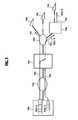
- Fig. 1 illustrates in a very simplified manner an example of an overall system to which the present invention is applicable.
- the system shown in Fig. 1 includes, in this particular embodiment, four end systems 10a, 10b, 10c, 10d, two subnetworks 12a, 12b, and two relay stations 14a, 14b.
- the end systems 10a-10d are interconnected via bold lines, and are able to exchange data (viz., PDUs) therebetween via the subnetworks 12a-12b and the relay stations 14a-14b.
- the end system 10a dispatches a PDU X which should be addressed to the end system 10d but has been erroneously directed to the end system 10b and (b) the PDU X has included data of a predetermined hold time for which the PDU X is retained in the relay station 14a.
- the station 14a retains same therewithin for the predetermined period of time, which ranges from more than 3 minutes to one hour merely by way of example.
- the relay station in which PDUs are to be stored for the purposes of destination correction, is previously determined when constructing the overall system.
- the PDU X is forwarded, as shown by an arrow 16a, from the end system 10a to the relay station 14a in which the PDU X is held for the predetermined time period.
- the destination change PDU Y is forwarded to the relay station 14a as shown by arrow 16b within the predetermined hold time period.
- the destination of the PDU X is changed at the relay station 14a from the end system 10b to 10d. Accordingly, when the predetermined hold time expires, the PDU X is routed to the correct end system 10d via the subnetwork 12b and the relay station 14b as shown by arrows 16c, 16d.
- the PDU X is erroneously routed to the end system 10b as indicated by the broken line arrow 16e.
- Fig. 2 shows a code format of each of the PDUs X and Y.
- the PDU X includes a PDU ID (Identification) code 20a, a PDU type code 20b, a transmission hold indicator 20c which indicates whether or not the PDU should be retained in a designated relay station, a destination address code 20d and a user data section 20e. If the indicator 20c holds a logic "1", the PDU is retained in the relay station 14a for the predetermined time period, while if the indicator 20c holds a logic "0" then the PDU will not be held in the relay station 14a and is dispatched to an end station as instructed.
- PDU ID Identity
- the destination change PDU Y includes a PDU ID code 22a, a PDU type code 22b, a target PDU indicator 22c and a correct destination address code 22e.
- the target PDU indicates, in this particular embodiment, the PDU X whose destination address should be corrected by the PDU Y.
- the PDU type code 20b represents that the PDU including same is a type containing user data
- the PDU type code 22c indicates that the PDU is for the destination change.
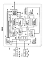
- FIG. 3 wherein the relay station 14a is shown in detail in block diagram form.
- each of the bold lines indicates a flow of the PDU X, while each of slim lines indicates a flow of control.
- a PDU receiver & dispatch controller 30 is supplied with the PDU X and directs same to a memory 32 which stores the PDU X.
- the controller 30 extracts and applies the transmission hold indicator 20c (Fig. 2), included in the PDU X received, to a hold time checker 34 via a line 80.
- the hold time detector 34 applies a control signal to a time-out check & transmitting circuit 36 via a control line 82.
- a logic "0" stored in the hold time indicator 20c indicates that the PDU X is not retained in the relay station 14a and, accordingly, the circuit 36 fetches the PDU X stored in the memory 32 via lines 84 and 86.
- the PDU X is directed to the subnetwork 12b (Fig. 2) via a line 88.
- the end system 10a usually attaches to the PDU X the transmission hold indicator 20c which assumes a logic "1". However, in the event of high traffic density (for example), the end system 10a controls such that the indicator 20c assumes a logic "0".
- a PDU hold controller 38 in response to a control signal outputted from the hold time detector 34 and appearing on a line 90, accesses the memory 32 via a line 92 and has the PDU X transferred to and stored in a main memory 40 via lines 94, 96.
- the PDU hold controller 38 writes the PDU X into the main memory 40, it attaches a time count data to the PDU X and increments the time count data up to the predetermined hold time.
- the main memory 40 has a memory capacity sufficient to memorize a large amount of PDUs. It should be noted that each of the PDUs stored in the main memory 40 is assigned the aforesaid time count data which is controlled by the PDU hold controller 38.
- the time-out check & transmitting circuit 36 checks to see, using a line 98, if there exists a PDU whose hold time exceeds the predetermined hold time period. In the event that the PDU X in question has been held in the main memory exceeding the predetermined time period, the circuit 36 determines the overtime storage of the PDU X within the main memory 40 and retrieves same via a line 100. Subsequently, the retrieved PDU X is forwarded to the subnetwork 12b (Fig. 1) via the line 88 under the control of the time-out check & transmitting circuit 36.
- the PDU receiver & dispatch controller 30 When the PDU receiver & dispatch controller 30 is supplied with the PDU Y, it applies same to a memory 42 via a line 102.
- the memory 42 stores the whole of the PDU Y inputted to the relay station 14a.
- the controller 30 simultaneously supplies a target PDU detector 44 with the target PDU indicator 22c (Fig. 2) via a line 104.
- the detector 44 checks to see if the target PDU specified by the target PDU indicator 22c applied from the controller 30, is stored in the main memory 40 or not via lines 106, 108.
- the detector 44 In the event that the detector 44 fails to find the PDU defined by the target PDU indicator 22c, the detector 44 supplies, via a line 110, a discarding circuit 46 with a control signal indicating that the target PDU has not been found. Following this, the discarding circuit 46 erases the PDU Y via a line 112.
- a destination address replacing controller 48 receives, via a line 114, a control signal indicating that the target PDU has been detected. Subsequently, the controller 48 retrieves the PDU Y from the memory 42 and replaces the original destination address included in the corresponding PDU (viz, PDU X in this case) with the one in the PDU Y, using a line 116.
- the PDU X which has been subject to the destination address renewal, is transmitted to the subnetwork 12b via the lines 100, 88 when the hold time assigned thereto lapses, the manner of which has been discussed in the above.
- the end system 10a dispatches the PDUs X and Y.
- the transmission hold indicator 20c assumes a logic "1" " or "0".
- the indicator 20c may assumes one of various values each of which indicates the hold time duraton.
- the value of the indicator 20c is set to an appropirate one depending on traffic conditions. By way of example, during heavy traffic, the value is set to a small one.
Landscapes
- Engineering & Computer Science (AREA)
- Computer Networks & Wireless Communication (AREA)
- Signal Processing (AREA)
- Data Exchanges In Wide-Area Networks (AREA)
- Small-Scale Networks (AREA)
- Computer And Data Communications (AREA)
- Communication Control (AREA)
Applications Claiming Priority (2)
| Application Number | Priority Date | Filing Date | Title |
|---|---|---|---|
| JP18751790A JP2580849B2 (ja) | 1990-07-16 | 1990-07-16 | 宛先アドレス変更ルーティング制御方式 |
| JP187517/90 | 1990-07-16 |
Publications (3)
| Publication Number | Publication Date |
|---|---|
| EP0467299A2 true EP0467299A2 (de) | 1992-01-22 |
| EP0467299A3 EP0467299A3 (de) | 1994-12-21 |
| EP0467299B1 EP0467299B1 (de) | 1999-05-19 |
Family
ID=16207464
Family Applications (1)
| Application Number | Title | Priority Date | Filing Date |
|---|---|---|---|
| EP19910111860 Expired - Lifetime EP0467299B1 (de) | 1990-07-16 | 1991-07-16 | Verfahren und Vorrichtung zur Änderung der Bestimmung einer Protokolldateneinheit in verbindunglosen Netzsystemen |
Country Status (4)
| Country | Link |
|---|---|
| US (1) | US5442339A (de) |
| EP (1) | EP0467299B1 (de) |
| JP (1) | JP2580849B2 (de) |
| DE (1) | DE69131243T2 (de) |
Families Citing this family (3)
| Publication number | Priority date | Publication date | Assignee | Title |
|---|---|---|---|---|
| JPH1049459A (ja) * | 1996-08-02 | 1998-02-20 | Nec Corp | 複数プロセスへの受信pdu配信方式 |
| US20020062415A1 (en) * | 2000-09-29 | 2002-05-23 | Zarlink Semiconductor N.V. Inc. | Slotted memory access method |
| ITVI20060355A1 (it) | 2006-12-14 | 2008-06-15 | Ciro Mastromatteo | Bussola di raccordo per la connessione di tubi a terminali |
Family Cites Families (7)
| Publication number | Priority date | Publication date | Assignee | Title |
|---|---|---|---|---|
| US4379946A (en) * | 1980-06-05 | 1983-04-12 | Nippon Telegraph & Telephone Public Corporation | Signalling system and signal control equipment for multi-address calling |
| US4875037A (en) * | 1982-10-29 | 1989-10-17 | American Telephone And Telegraph Company, At&T Bell Laboratories | Automatic rerouting of calls through data buses |
| JPH0771111B2 (ja) * | 1985-09-13 | 1995-07-31 | 日本電気株式会社 | パケツト交換処理装置 |
| DE3686629T2 (de) * | 1985-10-07 | 1993-03-18 | Nippon Electric Co | Paketvermittlungsnachrichtensystem hoher geschwindigkeit mit durchgehender fluesssteuerung und sendewiederholung. |
| JPS6285532A (ja) * | 1985-10-11 | 1987-04-20 | Nec Corp | パケツト交換システム |
| CA1264845A (en) * | 1987-03-13 | 1990-01-23 | Ernst August Munter | Digital telephone switching system having a message switch with address translation |
| US4994926C1 (en) * | 1988-09-22 | 2001-07-03 | Audiofax Ip L L C | Facsimile telecommunications system and method |
-
1990
- 1990-07-16 JP JP18751790A patent/JP2580849B2/ja not_active Expired - Fee Related
-
1991
- 1991-07-16 DE DE69131243T patent/DE69131243T2/de not_active Expired - Fee Related
- 1991-07-16 EP EP19910111860 patent/EP0467299B1/de not_active Expired - Lifetime
-
1993
- 1993-07-26 US US08/097,540 patent/US5442339A/en not_active Expired - Fee Related
Also Published As
| Publication number | Publication date |
|---|---|
| DE69131243D1 (de) | 1999-06-24 |
| JP2580849B2 (ja) | 1997-02-12 |
| US5442339A (en) | 1995-08-15 |
| EP0467299A3 (de) | 1994-12-21 |
| JPH0477024A (ja) | 1992-03-11 |
| DE69131243T2 (de) | 1999-09-09 |
| EP0467299B1 (de) | 1999-05-19 |
Similar Documents
| Publication | Publication Date | Title |
|---|---|---|
| EP0544018B1 (de) | System zur übermittlung von unterscheidungsinformation von paketleitwegen | |
| US5777987A (en) | Method and apparatus for using multiple FIFOs to improve flow control and routing in a communications receiver | |
| EP0462542A2 (de) | Verfahren und Gerät zur Adressenverwaltung der Send- und Empfangsnachrichten | |
| EP0537297B1 (de) | Verfahren und vorrichtung zur ziel- und quellenadressierung in einem paketnetz | |
| CA1316242C (en) | Control system for communication between units | |
| US5442339A (en) | Method and system of changing destination of protocol data unit in hierarchical data communication network systems | |
| US5619653A (en) | Buffer device with resender | |
| JPH09130408A (ja) | ネットワークインタフェース装置 | |
| US5200953A (en) | Method for programming a content addressable memory (CAM) | |
| JPS6324742A (ja) | パケツト交換輻輳抑止方式 | |
| US4879550A (en) | Method and system for loop communication | |
| JP2555902B2 (ja) | No.7共通線信号方式の信号ルート管理方法 | |
| US6822965B1 (en) | Approximate state control mechanism | |
| JP3428098B2 (ja) | ネットワークにおけるデータ転送方法 | |
| JP2658129B2 (ja) | データ伝送装置 | |
| JPH03224347A (ja) | 印刷データ転送方式 | |
| JPS60189343A (ja) | デ−タ通信方式及び装置 | |
| JPH0771099B2 (ja) | トークンパッシングデータ通信方式の端末装置 | |
| EP0760566A1 (de) | Datenübertragungssystem und übertragungsendgerät | |
| JPH0426262B2 (de) | ||
| JPH05110601A (ja) | 方路選択遠隔制御機能付きパケツト交換局及び方路選択遠隔制御方法 | |
| JPH02246647A (ja) | ファクシミリ装置及びファクシミリ蓄積交換装置 | |
| JPH06350610A (ja) | 応答確認方式 | |
| JPH04185067A (ja) | 宛先誤り訂正方式 | |
| JPH09116558A (ja) | メッセージ廃棄処理装置 |
Legal Events
| Date | Code | Title | Description |
|---|---|---|---|
| PUAI | Public reference made under article 153(3) epc to a published international application that has entered the european phase |
Free format text: ORIGINAL CODE: 0009012 |
|
| 17P | Request for examination filed |
Effective date: 19910814 |
|
| AK | Designated contracting states |
Kind code of ref document: A2 Designated state(s): DE FR GB |
|
| PUAL | Search report despatched |
Free format text: ORIGINAL CODE: 0009013 |
|
| AK | Designated contracting states |
Kind code of ref document: A3 Designated state(s): DE FR GB |
|
| 17Q | First examination report despatched |
Effective date: 19970327 |
|
| GRAG | Despatch of communication of intention to grant |
Free format text: ORIGINAL CODE: EPIDOS AGRA |
|
| GRAG | Despatch of communication of intention to grant |
Free format text: ORIGINAL CODE: EPIDOS AGRA |
|
| GRAG | Despatch of communication of intention to grant |
Free format text: ORIGINAL CODE: EPIDOS AGRA |
|
| GRAH | Despatch of communication of intention to grant a patent |
Free format text: ORIGINAL CODE: EPIDOS IGRA |
|
| GRAH | Despatch of communication of intention to grant a patent |
Free format text: ORIGINAL CODE: EPIDOS IGRA |
|
| GRAA | (expected) grant |
Free format text: ORIGINAL CODE: 0009210 |
|
| AK | Designated contracting states |
Kind code of ref document: B1 Designated state(s): DE FR GB |
|
| REF | Corresponds to: |
Ref document number: 69131243 Country of ref document: DE Date of ref document: 19990624 |
|
| ET | Fr: translation filed | ||
| PLBE | No opposition filed within time limit |
Free format text: ORIGINAL CODE: 0009261 |
|
| STAA | Information on the status of an ep patent application or granted ep patent |
Free format text: STATUS: NO OPPOSITION FILED WITHIN TIME LIMIT |
|
| 26N | No opposition filed | ||
| REG | Reference to a national code |
Ref country code: GB Ref legal event code: IF02 |
|
| PGFP | Annual fee paid to national office [announced via postgrant information from national office to epo] |
Ref country code: FR Payment date: 20050708 Year of fee payment: 15 |
|
| PGFP | Annual fee paid to national office [announced via postgrant information from national office to epo] |
Ref country code: GB Payment date: 20050713 Year of fee payment: 15 |
|
| PGFP | Annual fee paid to national office [announced via postgrant information from national office to epo] |
Ref country code: DE Payment date: 20050714 Year of fee payment: 15 |
|
| PG25 | Lapsed in a contracting state [announced via postgrant information from national office to epo] |
Ref country code: GB Free format text: LAPSE BECAUSE OF NON-PAYMENT OF DUE FEES Effective date: 20060716 |
|
| PG25 | Lapsed in a contracting state [announced via postgrant information from national office to epo] |
Ref country code: DE Free format text: LAPSE BECAUSE OF NON-PAYMENT OF DUE FEES Effective date: 20070201 |
|
| GBPC | Gb: european patent ceased through non-payment of renewal fee |
Effective date: 20060716 |
|
| REG | Reference to a national code |
Ref country code: FR Ref legal event code: ST Effective date: 20070330 |
|
| PG25 | Lapsed in a contracting state [announced via postgrant information from national office to epo] |
Ref country code: FR Free format text: LAPSE BECAUSE OF NON-PAYMENT OF DUE FEES Effective date: 20060731 |