EP0464645B1 - Computertomograph mit Scaneinrichtung - Google Patents
Computertomograph mit Scaneinrichtung Download PDFInfo
- Publication number
- EP0464645B1 EP0464645B1 EP91110579A EP91110579A EP0464645B1 EP 0464645 B1 EP0464645 B1 EP 0464645B1 EP 91110579 A EP91110579 A EP 91110579A EP 91110579 A EP91110579 A EP 91110579A EP 0464645 B1 EP0464645 B1 EP 0464645B1
- Authority
- EP
- European Patent Office
- Prior art keywords
- projection data
- scanning
- slice
- scannogram
- designated
- Prior art date
- Legal status (The legal status is an assumption and is not a legal conclusion. Google has not performed a legal analysis and makes no representation as to the accuracy of the status listed.)
- Expired - Lifetime
Links
- 238000002591 computed tomography Methods 0.000 title claims description 8
- 230000005855 radiation Effects 0.000 claims description 11
- 238000000034 method Methods 0.000 description 18
- 239000011295 pitch Substances 0.000 description 4
- 238000010586 diagram Methods 0.000 description 2
- 238000012986 modification Methods 0.000 description 2
- 230000004048 modification Effects 0.000 description 2
Images

Classifications
-
- A—HUMAN NECESSITIES
- A61—MEDICAL OR VETERINARY SCIENCE; HYGIENE
- A61B—DIAGNOSIS; SURGERY; IDENTIFICATION
- A61B6/00—Apparatus or devices for radiation diagnosis; Apparatus or devices for radiation diagnosis combined with radiation therapy equipment
- A61B6/02—Arrangements for diagnosis sequentially in different planes; Stereoscopic radiation diagnosis
- A61B6/03—Computed tomography [CT]
- A61B6/032—Transmission computed tomography [CT]
-
- A—HUMAN NECESSITIES
- A61—MEDICAL OR VETERINARY SCIENCE; HYGIENE
- A61B—DIAGNOSIS; SURGERY; IDENTIFICATION
- A61B6/00—Apparatus or devices for radiation diagnosis; Apparatus or devices for radiation diagnosis combined with radiation therapy equipment
- A61B6/02—Arrangements for diagnosis sequentially in different planes; Stereoscopic radiation diagnosis
- A61B6/027—Arrangements for diagnosis sequentially in different planes; Stereoscopic radiation diagnosis characterised by the use of a particular data acquisition trajectory, e.g. helical or spiral
-
- A—HUMAN NECESSITIES
- A61—MEDICAL OR VETERINARY SCIENCE; HYGIENE
- A61B—DIAGNOSIS; SURGERY; IDENTIFICATION
- A61B6/00—Apparatus or devices for radiation diagnosis; Apparatus or devices for radiation diagnosis combined with radiation therapy equipment
- A61B6/04—Positioning of patients; Tiltable beds or the like
- A61B6/0487—Motor-assisted positioning
Definitions
- the present invention relates to a computed tomography scanner apparatus (to be simply referred to as a CT scanner hereinafter) and, more particularly, to a reconstruction planning procedure of a CT scanner adopting a helical scanning scheme.
- a so-called scan planning procedure or a reconstruction planning procedure is performed to suppress unnecessary X-ray radiation to the object and improve diagnostic efficiency by reconstructing only a tomographic image of a desired slice portion.
- scan planning procedure it is determined before scanning which portion of the object is to be scanned to acquire projection data.
- reconstruction planning procedure it is determined a tomographic image of which slice is to be reconstructed from the acquired projection data.
- an X-ray tube is not rotated around the object but fixed immediately above or immediately beside the object.
- X-rays transmitted through the object are acquired while moving only the top plate of the bed in the direction of the body axis, and a scannogram of the object obtained by looking the object from the above or from its side is displayed.
- a scanning slice is designated by using a line cursor on the scannogram.
- the top plate is moved to cause the scanning position of the object to coincide with the position of the designated slice.
- the top plate is then stopped and the X-ray tube is rotated around the object.
- Ordinary scanning is performed and projection data of the scanning position is acquired.
- the top plate may be moved at predetermined pitches and stopped at every pitch shift, and ordinary scanning is performed in the same manner.
- projection data acquired in units of scanning positions (top plate shift positions) will be stored in an acquisition data memory.
- a slice to be reconstructed is designated on the scannogram. Then, projection data at a scanning position corresponding to the designated slice is read out from the acquisition data memory, and a tomographic image of the designated slice is reconstructed based on the readout data.
- An X-ray CT scanner of a helical scanning scheme has recently been developed in order to scan a large portion of an object at a high speed (see EP-A-0 113 879).
- the top plate of the bed on which the object is placed is continuously moved in the direction of the body axis, and the X-ray tube is continuously rotated around the object, thereby scanning the object.
- the path of the relative movement of the X-ray tube seen from the side of the object becomes helical.
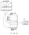
- projection data corresponding to a predetermined portion including a position designated on the scannogram are selected from acquired projection data, and a tomographic image of the designated position is reconstructed based on the selected projection data, thereby reconstructing the tomographic image of the position designated on the scannogram.
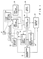
- the system controller 24 is provided for the overall control.
- An input device 26 for setting various conditions is connected to the system controller 24.
- the system controller 24 is also connected to the scannogram memory 16, the projection data memory 18, the image reconstruction circuit 20, and the display device 22.
- the system controller 24 controls a high voltage generator 28 for supplying a drive signal to the X-ray tube 12 and the X-ray tube holding member.
- control signals are supplied to an X-ray tube rotating actuator 30 for rotating the X-ray tube 12, and to a bed moving actuator 32 for moving the top plate 10.
- the position of the top plate 10 is detected by a position sensor 34 and input to the system controller 24.
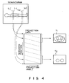
- the scan planning procedure which is not the subject-matter of the present invention, will be described with reference to Fig. 4.
- the scannogram mode is first executed, and it is determined, on a scannogram, a portion for which a tomographic image is to be obtained, i.e., which range is to be scanned.
- the X-ray tub 12 is fixed immediately beside the object to be examined, only the top plate 10 is continuously moved at a constant speed, and the scannogram of the entire sample body is scanned and displayed on the display device 22.
- Line cursors L 1 and L 2 are displayed on the scannogram by the operation of the input device 26, and a range between the cursors is designated as the scanning range.
Landscapes
- Health & Medical Sciences (AREA)
- Life Sciences & Earth Sciences (AREA)
- Engineering & Computer Science (AREA)
- Medical Informatics (AREA)
- Optics & Photonics (AREA)
- Biomedical Technology (AREA)
- Biophysics (AREA)
- High Energy & Nuclear Physics (AREA)
- Veterinary Medicine (AREA)
- Nuclear Medicine, Radiotherapy & Molecular Imaging (AREA)
- Public Health (AREA)
- Pathology (AREA)
- Radiology & Medical Imaging (AREA)
- Physics & Mathematics (AREA)
- Heart & Thoracic Surgery (AREA)
- Molecular Biology (AREA)
- Surgery (AREA)
- Animal Behavior & Ethology (AREA)
- General Health & Medical Sciences (AREA)
- Pulmonology (AREA)
- Theoretical Computer Science (AREA)
- Apparatus For Radiation Diagnosis (AREA)
Claims (4)
- Computertomographisches Abtastgerät miteiner Abtasteinrichtung (10, 12, 14, 28) zur Gewinnung von Projektionsdaten eines Objekts durch schraubenlinienförmige Abtastung des Objekts mittels eines Strahlungsstrahls,einer Speichereinrichtung (18) zum Speichern der Projektionsdaten, die durch die Abtasteinrichtung (10, 12, 14, 28) gewonnen werden,einer Einrichtung (10, 12, 14, 16) zur Gewinnung eines Scanogramms bzw. Abtastbilds des Objekts durch Aussenden eines Strahlungsstrahls zu dem Objekt,einer Einrichtung (26) zum Bezeichnen einer gewünschten Scheibe auf dem Abtastbild,einer Einrichtung (24) zum Auswahlen von Daten aus den Projektionsdaten, die in der Speichereinrichtung (18) gespeichert sind, wobei die Daten einem vorbestimmten Bereich entsprechen, der die durch die Bezeichnungseinrichtung (26) bezeichnete gewünschte Scheibe und erste und zweite Bereiche enthält, die vor und hinter der gewünschten Scheibe liegen, wobei die Auswähleinrichtung Projektionsdaten interpoliert, die zur Bildung eines Schnittbildes der bezeichneten Scheibe notwendig sind, undeiner Einrichtung (20) zum Rekonstruieren eines Schnittbilds der bezeichneten Scheibe aus den Daten, die dem durch die Auswähleinrichtung (24) ausgewählten Bereich entsprechen.
- Gerät nach Anspruch 1, dadurch gekennzeichnet, daß die Startposition des vorbestimmten Bereichs vor der gewünschten Scheibe in einem Abstand liegt, der der Strecke der Verschiebung des Objekts während eines Zyklus der schraubenlinienförmigen Abtastung entspricht, und die Endposition des vorbestimmten Bereichs hinter der gewünschten Scheibe mit einem Abstand liegt, der der Strecke der Verschiebung des Objekts während eines Zyklus der schraubenlinienförmigen Abtastung entspricht.
- Gerät nach Anspruch 1, dadurch gekennzeichnet, daß die Bezeichnungseinrichtung (26) einen gewünschten Abschnitt und auch die gewünschte Scheibe auf dem Abtastbild bezeichnet, und daß die Abtasteinrichtung (10, 12, 14, 28) einen vorbestimmten Bereich der Projektionsdaten zum Rekonstruieren der tomographischen Bilder von einer Startposition bis zu einer Endposition des gewünschten Abschnitts bestimmt und die Projektionsdaten des vorbestimmten Bereichs ausliest.
- Gerät nach Anspruch 3, dadurch gekennzeichnet, daß die Startposition des vorbestimmten Bereichs vor einer Startposition des gewünschten Abschnitts mit einem Abstand liegt, der der Strecke der Verschiebung des Objekts während eines Zyklus der schraubenlinienförmigen Abtastung entspricht, und die Endposition des vorbestimmten Bereichs hinter einer Endposition des gewünschten Abschnitts in einem Abstand liegt, der der Strecke der Verschiebung des Objekts während eines Zyklus der schraubenlinienförmigen Abtastung entspricht.
Priority Applications (1)
| Application Number | Priority Date | Filing Date | Title |
|---|---|---|---|
| EP96112112A EP0744158B1 (de) | 1990-06-27 | 1991-06-26 | Computertomograph-Abtastgerät |
Applications Claiming Priority (2)
| Application Number | Priority Date | Filing Date | Title |
|---|---|---|---|
| JP169382/90 | 1990-06-27 | ||
| JP2169382A JPH0787835B2 (ja) | 1990-06-27 | 1990-06-27 | X線断層撮影装置 |
Related Child Applications (1)
| Application Number | Title | Priority Date | Filing Date |
|---|---|---|---|
| EP96112112.6 Division-Into | 1996-07-26 |
Publications (2)
| Publication Number | Publication Date |
|---|---|
| EP0464645A1 EP0464645A1 (de) | 1992-01-08 |
| EP0464645B1 true EP0464645B1 (de) | 1997-05-28 |
Family
ID=15885565
Family Applications (2)
| Application Number | Title | Priority Date | Filing Date |
|---|---|---|---|
| EP96112112A Expired - Lifetime EP0744158B1 (de) | 1990-06-27 | 1991-06-26 | Computertomograph-Abtastgerät |
| EP91110579A Expired - Lifetime EP0464645B1 (de) | 1990-06-27 | 1991-06-26 | Computertomograph mit Scaneinrichtung |
Family Applications Before (1)
| Application Number | Title | Priority Date | Filing Date |
|---|---|---|---|
| EP96112112A Expired - Lifetime EP0744158B1 (de) | 1990-06-27 | 1991-06-26 | Computertomograph-Abtastgerät |
Country Status (4)
| Country | Link |
|---|---|
| US (1) | US5212717A (de) |
| EP (2) | EP0744158B1 (de) |
| JP (1) | JPH0787835B2 (de) |
| DE (2) | DE69126243T2 (de) |
Families Citing this family (29)
| Publication number | Priority date | Publication date | Assignee | Title |
|---|---|---|---|---|
| US5485493A (en) * | 1988-10-20 | 1996-01-16 | Picker International, Inc. | Multiple detector ring spiral scanner with relatively adjustable helical paths |
| JP2607749B2 (ja) * | 1990-11-01 | 1997-05-07 | 株式会社東芝 | X線ct装置 |
| JP2829122B2 (ja) * | 1990-11-14 | 1998-11-25 | 株式会社東芝 | 画像表示装置 |
| US5454019A (en) * | 1991-03-15 | 1995-09-26 | Hitachi, Ltd. | Computed tomography system |
| EP0504855B1 (de) * | 1991-03-20 | 1998-06-10 | Kabushiki Kaisha Toshiba | Röntgenstrahl-Computertomograph |
| US5367552A (en) * | 1991-10-03 | 1994-11-22 | In Vision Technologies, Inc. | Automatic concealed object detection system having a pre-scan stage |
| DE4137031C1 (en) * | 1991-11-11 | 1993-04-08 | Siemens Ag, 8000 Muenchen, De | Computer tomograph equipment providing three=dimensional scanning - relatively rotates measuring unit, consisting of X=ray radiator and radiation detector, and patient couch |
| US5317616A (en) * | 1992-03-19 | 1994-05-31 | Wisconsin Alumni Research Foundation | Method and apparatus for radiation therapy |
| US5661773A (en) * | 1992-03-19 | 1997-08-26 | Wisconsin Alumni Research Foundation | Interface for radiation therapy machine |
| DE4223430C1 (de) * | 1992-06-24 | 1993-11-11 | Siemens Ag | Computertomograph mit Mitteln zur Darstellung von Schattenbildern |
| US5386446A (en) * | 1992-07-06 | 1995-01-31 | Kabushiki Kaisha Toshiba | Positional adjustment of resolution in radiation CT scanner |
| JPH08511452A (ja) * | 1993-06-09 | 1996-12-03 | ウイスコンシン アラムナイ リサーチ フオンデーシヨン | 抑制された回転自由度を有する放射治療システムおよび動的コリメータ |
| US5541971A (en) * | 1993-09-06 | 1996-07-30 | Kabushiki Kaisha Toshiba | X-ray computerized tomography apparatus |
| US5513237A (en) * | 1993-11-26 | 1996-04-30 | Kabushiki Kaisha Toshiba | Computerized tomography apparatus |
| JP3583503B2 (ja) * | 1995-04-13 | 2004-11-04 | 株式会社日立メディコ | 医療用診断ct装置 |
| IL119714A0 (en) | 1996-11-28 | 1997-02-18 | Elscint Ltd | CT system with oblique image planes |
| DE19961524A1 (de) * | 1999-12-20 | 2001-07-05 | Siemens Ag | Verfahren zum Betrieb eines CT-Gerätes |
| DE10234465A1 (de) * | 2002-07-29 | 2004-02-12 | Siemens Ag | Verfahren zur Schichthöhenpositionierung |
| JP4568023B2 (ja) * | 2004-05-13 | 2010-10-27 | 株式会社東芝 | X線コンピュータ断層撮影装置 |
| JP4549780B2 (ja) * | 2004-08-27 | 2010-09-22 | ジーイー・メディカル・システムズ・グローバル・テクノロジー・カンパニー・エルエルシー | 被検体移動装置および撮影装置 |
| JP4901159B2 (ja) * | 2005-08-31 | 2012-03-21 | 株式会社東芝 | X線ct装置及びx線撮影方法 |
| JP2008006032A (ja) * | 2006-06-29 | 2008-01-17 | Ge Medical Systems Global Technology Co Llc | X線ct装置およびx線ct撮影方法 |
| CN102525524B (zh) * | 2010-12-20 | 2013-11-06 | 上海西门子医疗器械有限公司 | 用于定位像扫描的定位装置和方法 |
| CN103338706B (zh) * | 2011-01-26 | 2016-05-04 | 皇家飞利浦有限公司 | 临床环境控制系统 |
| CN102908161A (zh) * | 2012-10-26 | 2013-02-06 | 东软飞利浦医疗设备系统有限责任公司 | 一种ct系统的扫描定位方法 |
| CN104107063B (zh) * | 2013-04-18 | 2018-05-04 | 上海联影医疗科技有限公司 | 一种医学图像扫描方法及装置 |
| CN105433971A (zh) * | 2014-07-29 | 2016-03-30 | 上海西门子医疗器械有限公司 | 计算机断层扫描方法和设备 |
| US11688071B2 (en) | 2020-03-19 | 2023-06-27 | Shanghai United Imaging Healthcare Co., Ltd. | Systems and methods for image reconstruction and processing |
| CN111402356B (zh) * | 2020-03-19 | 2024-04-16 | 上海联影医疗科技股份有限公司 | 参数成像输入函数提取方法、装置和计算机设备 |
Family Cites Families (11)
| Publication number | Priority date | Publication date | Assignee | Title |
|---|---|---|---|---|
| NL8003355A (nl) * | 1980-06-09 | 1982-01-04 | Philips Nv | Medisch stralingsonderzoekapparaat. |
| JPS5894833A (ja) * | 1981-12-01 | 1983-06-06 | 株式会社東芝 | X線ct装置 |
| JPS59111738A (ja) * | 1982-12-16 | 1984-06-28 | 株式会社東芝 | X線断層撮影装置 |
| JPS59155238A (ja) * | 1983-02-24 | 1984-09-04 | 株式会社東芝 | X線ct装置 |
| JPS60182934A (ja) * | 1984-02-29 | 1985-09-18 | 横河メディカルシステム株式会社 | 計算機トモグラフイ装置の表示装置 |
| JPH0767445B2 (ja) * | 1985-10-14 | 1995-07-26 | 株式会社日立メディコ | X線ct装置 |
| US4789929A (en) * | 1987-05-14 | 1988-12-06 | Hitachi Medical Corporation | CT system for spirally scanning subject on a movable bed synchronized to X-ray tube revolution |
| NL8802556A (nl) * | 1988-10-18 | 1990-05-16 | Philips Nv | Computertomografiescanner met tomosynthetisch scanogram. |
| JPH0728862B2 (ja) * | 1989-02-13 | 1995-04-05 | 株式会社東芝 | Ct装置 |
| US5046003A (en) * | 1989-06-26 | 1991-09-03 | General Electric Company | Method for reducing skew image artifacts in helical projection imaging |
| US5090037A (en) * | 1990-11-19 | 1992-02-18 | General Electric Company | Helical scanning computed tomography with tracking x-ray source |
-
1990
- 1990-06-27 JP JP2169382A patent/JPH0787835B2/ja not_active Expired - Lifetime
-
1991
- 1991-06-26 US US07/721,311 patent/US5212717A/en not_active Expired - Lifetime
- 1991-06-26 DE DE69126243T patent/DE69126243T2/de not_active Expired - Fee Related
- 1991-06-26 EP EP96112112A patent/EP0744158B1/de not_active Expired - Lifetime
- 1991-06-26 DE DE69133139T patent/DE69133139T2/de not_active Expired - Fee Related
- 1991-06-26 EP EP91110579A patent/EP0464645B1/de not_active Expired - Lifetime
Also Published As
| Publication number | Publication date |
|---|---|
| JPH0458944A (ja) | 1992-02-25 |
| EP0464645A1 (de) | 1992-01-08 |
| US5212717A (en) | 1993-05-18 |
| EP0744158A3 (de) | 1997-05-14 |
| DE69133139T2 (de) | 2003-10-16 |
| EP0744158B1 (de) | 2002-10-23 |
| DE69126243D1 (de) | 1997-07-03 |
| EP0744158A2 (de) | 1996-11-27 |
| JPH0787835B2 (ja) | 1995-09-27 |
| DE69126243T2 (de) | 1998-01-22 |
| DE69133139D1 (de) | 2002-11-28 |
Similar Documents
| Publication | Publication Date | Title |
|---|---|---|
| EP0464645B1 (de) | Computertomograph mit Scaneinrichtung | |
| US7154988B2 (en) | X-ray computed tomographic imaging apparatus | |
| US6922457B2 (en) | Computer tomography apparatus | |
| US5073911A (en) | Computerized tomographic apparatus | |
| US4630202A (en) | Computerized tomographic apparatus utilizing a radiation source | |
| JP4384766B2 (ja) | 物体の画像を形成する方法及びイメージング・システム | |
| JP4465062B2 (ja) | 計算機式断層写真装置 | |
| US6435714B1 (en) | X-ray diagnostic device | |
| US5173852A (en) | Computed tomography system with translatable focal spot | |
| EP0426464A2 (de) | Rechnergesteurtes tomographisches Bildrekonstruktionsverfahren für Spiralabtasten | |
| US20030072419A1 (en) | Computed tomography method and apparatus for acquiring images dependent on a time curve of a periodic motion of the subject | |
| US5682414A (en) | X-ray computerized tomography apparatus | |
| JP4612294B2 (ja) | X線コンピュータ断層装置、x線コンピュータ断層装置制御方法、及びx線コンピュータ断層撮影プログラム | |
| USRE41219E1 (en) | Apparatus and method for X-ray computer tomography | |
| US6870898B1 (en) | Computed tomography apparatus with automatic parameter modification to prevent impermissible operating states | |
| JPH10146331A (ja) | 対象物の関心ある領域の3次元コンピュータトモグラフ撮影のための走査及びデータ取得方法および装置 | |
| JP4416884B2 (ja) | コンピュータトモグラフの像再構成方法 | |
| EP0200939B1 (de) | Emissionscomputertomographievorrichtung | |
| US5539796A (en) | Spiral scanning type x-ray CT apparatus | |
| JP4406106B2 (ja) | X線ct装置 | |
| JPH09294739A (ja) | X線ct装置 | |
| JP4551612B2 (ja) | コンピュータ断層撮影装置 | |
| JPH0471540A (ja) | X線ct装置 | |
| US6463117B1 (en) | Methods and apparatus for tilted helical image reconstruction in CT imaging | |
| JP2000102532A (ja) | X線ctスキャナ |
Legal Events
| Date | Code | Title | Description |
|---|---|---|---|
| PUAI | Public reference made under article 153(3) epc to a published international application that has entered the european phase |
Free format text: ORIGINAL CODE: 0009012 |
|
| 17P | Request for examination filed |
Effective date: 19910626 |
|
| AK | Designated contracting states |
Kind code of ref document: A1 Designated state(s): DE |
|
| 17Q | First examination report despatched |
Effective date: 19940428 |
|
| GRAG | Despatch of communication of intention to grant |
Free format text: ORIGINAL CODE: EPIDOS AGRA |
|
| GRAH | Despatch of communication of intention to grant a patent |
Free format text: ORIGINAL CODE: EPIDOS IGRA |
|
| GRAH | Despatch of communication of intention to grant a patent |
Free format text: ORIGINAL CODE: EPIDOS IGRA |
|
| GRAA | (expected) grant |
Free format text: ORIGINAL CODE: 0009210 |
|
| AK | Designated contracting states |
Kind code of ref document: B1 Designated state(s): DE |
|
| DX | Miscellaneous (deleted) | ||
| REF | Corresponds to: |
Ref document number: 69126243 Country of ref document: DE Date of ref document: 19970703 |
|
| PLBE | No opposition filed within time limit |
Free format text: ORIGINAL CODE: 0009261 |
|
| STAA | Information on the status of an ep patent application or granted ep patent |
Free format text: STATUS: NO OPPOSITION FILED WITHIN TIME LIMIT |
|
| 26N | No opposition filed | ||
| PGFP | Annual fee paid to national office [announced via postgrant information from national office to epo] |
Ref country code: DE Payment date: 20090619 Year of fee payment: 19 |
|
| PG25 | Lapsed in a contracting state [announced via postgrant information from national office to epo] |
Ref country code: DE Free format text: LAPSE BECAUSE OF NON-PAYMENT OF DUE FEES Effective date: 20110101 |