EP0464574A1 - Elément de fixation - Google Patents
Elément de fixation Download PDFInfo
- Publication number
- EP0464574A1 EP0464574A1 EP91110412A EP91110412A EP0464574A1 EP 0464574 A1 EP0464574 A1 EP 0464574A1 EP 91110412 A EP91110412 A EP 91110412A EP 91110412 A EP91110412 A EP 91110412A EP 0464574 A1 EP0464574 A1 EP 0464574A1
- Authority
- EP
- European Patent Office
- Prior art keywords
- fastening element
- section
- shaft
- element according
- anchoring member
- Prior art date
- Legal status (The legal status is an assumption and is not a legal conclusion. Google has not performed a legal analysis and makes no representation as to the accuracy of the status listed.)
- Granted
Links
- 238000004873 anchoring Methods 0.000 claims abstract description 110
- 125000006850 spacer group Chemical group 0.000 claims abstract description 30
- 239000000463 material Substances 0.000 claims description 23
- 230000002093 peripheral effect Effects 0.000 claims description 7
- 238000005452 bending Methods 0.000 claims description 5
- 230000035515 penetration Effects 0.000 claims description 4
- 238000005476 soldering Methods 0.000 claims description 3
- 238000004026 adhesive bonding Methods 0.000 claims description 2
- 238000003466 welding Methods 0.000 claims description 2
- 238000005219 brazing Methods 0.000 claims 1
- 238000004519 manufacturing process Methods 0.000 abstract description 5
- 239000002184 metal Substances 0.000 abstract 1
- 239000004567 concrete Substances 0.000 description 9
- 238000005553 drilling Methods 0.000 description 8
- 230000015572 biosynthetic process Effects 0.000 description 4
- 238000005755 formation reaction Methods 0.000 description 4
- 239000002023 wood Substances 0.000 description 4
- 230000006835 compression Effects 0.000 description 3
- 238000007906 compression Methods 0.000 description 3
- 238000003780 insertion Methods 0.000 description 2
- 230000037431 insertion Effects 0.000 description 2
- 241000209035 Ilex Species 0.000 description 1
- 229910000639 Spring steel Inorganic materials 0.000 description 1
- 239000011449 brick Substances 0.000 description 1
- 239000000919 ceramic Substances 0.000 description 1
- 238000005253 cladding Methods 0.000 description 1
- 239000002131 composite material Substances 0.000 description 1
- 238000010276 construction Methods 0.000 description 1
- 230000006735 deficit Effects 0.000 description 1
- 230000000694 effects Effects 0.000 description 1
- 230000002349 favourable effect Effects 0.000 description 1
- 238000002347 injection Methods 0.000 description 1
- 239000007924 injection Substances 0.000 description 1
- 238000001746 injection moulding Methods 0.000 description 1
- 238000003825 pressing Methods 0.000 description 1
- 239000011150 reinforced concrete Substances 0.000 description 1
- 239000007779 soft material Substances 0.000 description 1
- 239000007787 solid Substances 0.000 description 1
- 229910001220 stainless steel Inorganic materials 0.000 description 1
- 239000010935 stainless steel Substances 0.000 description 1
- 230000007704 transition Effects 0.000 description 1
- XLYOFNOQVPJJNP-UHFFFAOYSA-N water Substances O XLYOFNOQVPJJNP-UHFFFAOYSA-N 0.000 description 1
Images


Classifications
-
- F—MECHANICAL ENGINEERING; LIGHTING; HEATING; WEAPONS; BLASTING
- F16—ENGINEERING ELEMENTS AND UNITS; GENERAL MEASURES FOR PRODUCING AND MAINTAINING EFFECTIVE FUNCTIONING OF MACHINES OR INSTALLATIONS; THERMAL INSULATION IN GENERAL
- F16B—DEVICES FOR FASTENING OR SECURING CONSTRUCTIONAL ELEMENTS OR MACHINE PARTS TOGETHER, e.g. NAILS, BOLTS, CIRCLIPS, CLAMPS, CLIPS OR WEDGES; JOINTS OR JOINTING
- F16B21/00—Means for preventing relative axial movement of a pin, spigot, shaft or the like and a member surrounding it; Stud-and-socket releasable fastenings
- F16B21/06—Releasable fastening devices with snap-action
- F16B21/08—Releasable fastening devices with snap-action in which the stud, pin, or spigot has a resilient part
- F16B21/084—Releasable fastening devices with snap-action in which the stud, pin, or spigot has a resilient part with a series of flexible ribs or fins extending laterally from the shank of the stud, pin or spigot, said ribs or fins deforming predominantly in a direction parallel to the direction of insertion of the shank
-
- F—MECHANICAL ENGINEERING; LIGHTING; HEATING; WEAPONS; BLASTING
- F16—ENGINEERING ELEMENTS AND UNITS; GENERAL MEASURES FOR PRODUCING AND MAINTAINING EFFECTIVE FUNCTIONING OF MACHINES OR INSTALLATIONS; THERMAL INSULATION IN GENERAL
- F16B—DEVICES FOR FASTENING OR SECURING CONSTRUCTIONAL ELEMENTS OR MACHINE PARTS TOGETHER, e.g. NAILS, BOLTS, CIRCLIPS, CLAMPS, CLIPS OR WEDGES; JOINTS OR JOINTING
- F16B13/00—Dowels or other devices fastened in walls or the like by inserting them in holes made therein for that purpose
- F16B13/02—Dowels or other devices fastened in walls or the like by inserting them in holes made therein for that purpose in one piece with protrusions or ridges on the shaft
-
- F—MECHANICAL ENGINEERING; LIGHTING; HEATING; WEAPONS; BLASTING
- F16—ENGINEERING ELEMENTS AND UNITS; GENERAL MEASURES FOR PRODUCING AND MAINTAINING EFFECTIVE FUNCTIONING OF MACHINES OR INSTALLATIONS; THERMAL INSULATION IN GENERAL
- F16B—DEVICES FOR FASTENING OR SECURING CONSTRUCTIONAL ELEMENTS OR MACHINE PARTS TOGETHER, e.g. NAILS, BOLTS, CIRCLIPS, CLAMPS, CLIPS OR WEDGES; JOINTS OR JOINTING
- F16B13/00—Dowels or other devices fastened in walls or the like by inserting them in holes made therein for that purpose
- F16B13/002—Dowels or other devices fastened in walls or the like by inserting them in holes made therein for that purpose self-cutting
Definitions
- the present invention relates to a fastening element which has a shaft with a head end and a foot end and at least one anchoring member surrounding the shaft for anchoring the fastening element in an opening formed in a component.
- fasteners are usually one-piece plastic products.
- the shape and design of such fasteners change depending on the intended use, not least of the material of the component in which a fastener is to be inserted. It follows that a large number of different tools, e.g. Injection molds is necessary, which increases the cost of manufacturing the individual fastener.
- the known fastening elements have the disadvantage that the anchoring member and shaft are made of the same material, which sets limits according to the production, e.g. the shaft and the anchoring members must consist of the same material.
- the invention seeks to remedy this.
- the invention as characterized in the claims, achieves the object of creating a fastening element in which the anchoring members are lined up on a shaft and are designed as separate components from the same.
- the advantages achieved by the invention are essentially to be seen in the fact that the anchoring members can be made of a material different from the shank and that differently designed anchoring members can be used with one and the same embodiment of a shank, which can reduce manufacturing costs.
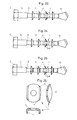
- the fastening element shown in FIG. 1 has a shaft 1 with a head end 2, which head end 2 is designed in this embodiment such that the fastening element can be driven into an opening in a component by means of hammer blows.
- the shaft 1 then has a first section 10 at the head end 2, which, as can be seen from the drawing, is smooth-walled, which first section 10 is followed by a second section 11 drawn in broken lines.
- a step acting as a stop 9 is present in the shaft 1 between the first section 10 and the second section 11.
- the shaft 1 finally ends at the foot end 3.
- On the second section 11 of the shaft 1 there is now a number of disk-shaped anchoring members 4, which will be discussed in more detail below.
- the anchoring members 4 are held at a mutual distance by spacers 14, which spacers 14 are sleeve-shaped bodies, which are either individually pushed between the respective anchoring members 4 or are each formed in one piece with an anchoring member 4.
- the reference number 12 designates, for example, a compression at the transition from the second section 11 of the shaft 1 to the foot end 3 thereof, by means of which compression an axial pressure is exerted on the anchoring members 4 lined up on the second section 11 of the shaft 1, so that this is between the locking section 12 serving upsetting and the stop 9 are locked against axial movement relative to the shaft 1 on the same.
- the anchoring members 4 are resilient, so that when inserted into an opening in a component they are somewhat bent in relation to the circumference and accordingly exert a force against the inner wall of the opening, which is increased under a pull-out load that the edge sections of the anchoring members 4 are securely anchored in the inner wall of the respective opening. It can also be seen from FIG. 1 that the anchoring members 4 are plate-shaped.
- the anchoring members 4 endeavor to straighten up a little, which increases the pressure exerted on the second section 11 of the shaft 1 or creates a pressure and creates a clamping effect between the anchoring members 4 and the second section 11 which, in cooperation with the compression 12, ie the locking section on the second section, prevents a relative movement between the anchoring members 4 and the shaft 1, so that the fastening element is firmly anchored in the respective opening into which it has been driven.
- FIG. 2 shows an embodiment of anchoring members 4, which has a disk-shaped or plate-shaped ring body 5, which is formed in one piece with a spacer 14 in each case.
- the fastener equipped with such anchoring members 4 is driven in the direction of arrow A into the respective opening. It is locked against being pulled out by anchoring the edge section 21 in the respective inner wall of the opening.
- This edge section 21 can have the most varied of forms of formation, can be sharpened and have further formations which support penetration into the material of the opening and thus anchoring in the same.
- the ring body 5 is formed in one piece with a spacer 14, which in turn has a first section 15 and a second section 16.
- the inside diameter of the first section 15 of the spacer 14 is dimensioned relative to the outside diameter of the second section 16 such that a respective second section 16 can be nested into a respective first section 15, with a number of such anchoring members 4 on the second when the fastening element is finished Section 11 of the shaft 1 are lined up.
- the anchoring member arranged according to FIG. 2 at the left end of the group of anchoring members 4 lies against the stop 9 (see FIG. 1) and the anchoring member located at the right end abuts against the respective locking section 12 via the second section 16 of the spacer 14.
- a corresponding number of anchoring members 4 can now be lined up on a given shank 1 and it is also possible to manufacture a shank 1 from a given material, but for the anchoring members 4 depending on e.g. Material in which the fastening element is to be used, regardless of the material of the shaft 1, to select a different material.
- the anchoring members 4 have a different requirement than e.g. in the case of a brick, in the case of concrete, etc.
- the shaft 1, as often required in construction is rustproof, e.g. is made of stainless steel and the anchoring members 4 are made of a material which is adapted to the material of the component in which the fastening element is used, e.g. made of spring steel, ceramic, a composite or plastic.
- the anchoring member 4 is in the form of a wedge sleeve, or several such wedge sleeves are lined up on a second section 11 of the shaft 1 of the fastening element.
- the anchoring member 4 has a truncated cone-shaped outer jacket. On the inside, it has a frustoconical inner casing section 18, which is followed by a cylindrical inner casing section 19.
- This anchoring member 4 is again formed from an annular body 5 anchored in the respective edge of the opening, followed in one piece by a spacer 14.
- the ring body 5 is probably drawn as a solid body in FIG. 3, but can take on one of the configurations shown in FIGS. 4-13 below, in order to allow a respective opening to be elastically deflected against the shaft 1 when the fastening element is inserted.
- the wedge sleeve stiffness can be selected by a suitable choice of the material and also the respective thickness.
- Such a fastening element can already fully fulfill its purpose when equipped with one or two such anchoring members 4.
- the direction of insertion of the fastening element is again indicated by the arrow A in FIG.
- the spacer 14 has a chamfer 22 on the end in the direction of insertion, in order to simplify driving into a pre-drilled hole in the concrete, for example.
- the angle a between the outer casing and the fastening element parallel to the longitudinal axis is 3 ° and the angle ⁇ between the inner casing of the ring body 5 and the parallel to the longitudinal axis 5 ⁇ .
- FIGS. 4-13 Examples of such cross-sectional shapes are shown in FIGS. 4-13, it being pointed out that, in the case of the disk shown in each case, the formations along the circumference and the formations in the middle hole do not necessarily both have to occur simultaneously according to the drawings, i.e. the circumferential shape according to FIG. 4 can easily be implemented with a circular central opening.
- the ring body 5 of the anchoring member 4 shown in FIG. 4 has recesses 6 or projections 7 along the circumference, so that there is a serrated circumferential shape.
- the tips of the projections 7 obviously facilitate penetration into the inner wall of a respective opening.
- the middle hole also has projections and recesses, so that on the one hand, depending on the selected material of the shaft 1, there is an increased transfer of clamping force from the ring body 5 to the shaft 1 or that it is ensured that the anchoring member 4 is secured on the shaft 1 against rotation.
- the right side of Figure 4 shows a section through the ring body 5, which is plate-shaped in this embodiment. It should be noted that the position of the ring body 5 at an angle to the axis 23 is purely for example.
- FIG. 5 shows an embodiment in which recesses 6 or projections 7 are likewise formed along the circumference and the central hole has a similar inner circumferential shape.
- FIG. 6 also shows an embodiment equipped with recesses 6 and projections 7, the central hole being roughly square.
- the embodiment according to FIG. 7 shows a circumferential shape which contains straight edge sections with obtuse-angled projections 7.
- slots 8 are shown, which simplify the elastic bending of the ring body 5 when inserted into a hole.
- the edges of such slots do not necessarily have to touch, the slot can diverge slightly in a radial V-shape in the radial direction in order to simplify the bending when inserting into a respective hole or opening.
- the middle hole of the embodiment according to FIG. 7 is out of round here.
- FIG. 9 shows a cross-sectional design of the ring body 5 with a further example of the shape of the middle hole. Another embodiment of a triangular shape with curvilinear side walls is shown in FIG. 10.
- the embodiment according to FIG. 11 has slots 8 running in the radial direction, which again simplify the elastic bending when inserted into a hole.
- the slots 8 of the embodiment according to FIG. 12 run tangentially to the longitudinal center line of the ring body 5 and the slots 8 of the embodiment of FIG. 13 run in an arc shape.
- the design of the slots 8 according to FIGS. 12 and 13 can be advantageous if the fastening element is driven into a respective hole with a rotary movement, in which the sections of the ring body 5 located between the respective slots 8 twist somewhat in a propeller shape when screwed in.
- This version can e.g. then be advantageous if the fastening element, as will be described further below, is designed as a self-drilling fastening element.
- FIGS. 14-18 show different cross-sectional shapes of the shaft 1, or in particular of the second section 11 of the shaft 1, on which second section 11 the respective ring bodies 5 or anchoring members 4 are lined up. These cross-sectional shapes shown correspond to the respective central holes of the above-mentioned designs of the cross-sectional shapes of ring bodies 5.
- FIG. 19 shows anchoring members 4, in which the ring body 5 is formed in one piece with the spacer 14, for example as a simple stamped product. These anchoring members 4 are again lined up on the second section 11 of the shaft 1. This version is remarkable the curly course of the drawn cross-section of the ring body 5, which is tapered sharply towards the edge.
- FIG. 20 shows an embodiment in which the cross section of the ring bodies 5 of the anchoring members 4 is arcuate and is again formed in one piece with the respective spacer 14. Here too there is a sharp-edged peripheral edge.
- anchoring members 5 are formed in one piece with a sleeve 24.
- a sleeve 24 Such an embodiment can be chosen, for example, if the material of the anchoring members 4 is suitable for injection molding.
- the spacer 14 of the embodiment according to FIG. 21 is formed by a projection at the left end of the sleeve 24 here.
- FIG. 22 shows an anchoring member 4, in which the annular body 5 is formed in one piece with the spacer 14 and has a slot 8 which is continuous in the radial direction at one point.
- the peripheral edge of the ring body 5 is sharpened, as indicated by the angle y. It is obvious that in all designs the circumferential edge of the respective ring bodies 5 can not only be structured differently depending on the particular application (FIGS. 4-10), but can also be sharpened differently.
- FIG. 23 in particular shows a fastening element which is equipped with a drill bit 13, that is to say a self-drilling fastening element.
- the head end 2 of the shaft 1 is designed in the shape of a nut in order to be able to interact with a corresponding tool.
- the first section 10 and the second section 11 of the shaft 1 can be clearly seen, which have different diameters, with which the shoulder serving as a stop 9 is formed. It should be noted that the illustration is only to clarify the various sections of the shaft 1 described, but is not necessarily connected to the illustrated arrangement of the anchoring members 4. In the embodiment according to FIG.
- FIG. 24 shows an embodiment in which the anchoring members 4 are anchored in ring grooves or notches 25 in the shaft 1.
- This exemplary embodiment also shows the fastening element as a self-drilling fastening element with a drill bit 13 and again the first 10 and second section 11 of the shaft 1, which have different diameters.
- FIG. 25 shows an embodiment in which the anchoring members 4 are positively connected to the shaft 1 via compressed knobs 26.
- FIG. 26 shows a further embodiment of an anchoring member 4.
- edge sections 17 of the ring body 5 are designed to be angled, so that they act as spacers in that their edges rest against the axially adjoining anchoring member 4 in order to determine the mutual distance.
- FIG. 27 shows the foot end 3 of a shaft 1, in particular of the second section 11.
- the foot section 3 By pressing the foot section 3 together, it has been deformed in a wedge or cone shape to form a locking section 12. If a pulling force acts on the fastening element, this locking section 12 exerts a force acting in the widening direction of the anchoring member (r) 4 lying directly against it, i.e. in the radial direction of the ring body 5, thus anchoring it in the wall of the respective hole or the respective one Opening in which the fastener is inserted is reinforced.
- FIG. 28 shows a further possible embodiment of the foot end 3 of the shaft 1, which is also wedge-shaped.
- the part adjoining the locking section 12 is designed as a threaded pin so that it can be screwed into the end of the shaft.
- FIG. 30 shows an embodiment as a self-drilling fastening element.
- the first section 10 of the shaft 1 adjoins the head end 2, which is designed for the force-transmitting connection with a tool, followed by the stop 9 and the second section 11 of the shaft 1.
- the anchoring members 4 with the ring bodies 5 are on this second section 11 and the spacers 14 arranged between them, which can be separate sleeves or sleeves formed in one piece with the ring bodies 5.
- the foot end 3 of the shaft 1 is plastically deformed to form the locking section 12, with this deformation the anchoring members 4 are held clamped between the same and the stop 9.
- this locking section 12 is wedge-shaped, similar to the illustration in FIG. 27, so that when a pulling force directed to the right in FIG.
- the illustrated embodiment shows a further variant of the shaft 1, which is possible in all the exemplary embodiments.
- the shaft 1 is formed with a third section 101, which has an even larger diameter than the first section 10.
- the diameter of the third section 101 can at least correspond to the pre-drilling diameter for the fastening element, so that no radial play can occur in the area of the head end 2 of the fastening element used.
- FIG. 31 shows a further embodiment of the fastening element which, owing to the fact that the anchoring members are separate components from the shaft, contains two different types and also anchoring members which are effective in the opposite direction.
- This fastening element can serve, for example, to hold two bodies made of different materials together.
- a component H made of wood is connected to a component B made of concrete.
- the foot end 3 of the fastening element has a locking section 12, which is designed, for example, to be the same as that shown in FIG. 27.
- two anchoring members 4 are connected according to the embodiment according to FIG. 3, which, as has been stated on the basis of the description of the figures, are suitable for anchoring in concrete.
- a spacer 27 is then connected to anchoring members 4 with ring bodies 5 and spacers 14, which are designed according to any embodiment of the disk-shaped or plate-shaped designs.
- the rightmost outermost anchoring member lies on the shoulder of the second section 10 of the shaft, which has a somewhat larger diameter compared to the first, which ends at the head end 2, which is designed such that the fastening element can be driven in with hammer blows.
- a blind hole can be drilled in the concrete and the fastener can then be driven into this blind hole.
- a further blind hole can also be made in the component as wood at a corresponding point (or at corresponding points) and then this component made of wood can be pushed or pressed onto the fastening element protruding from the concrete component.
- the fastener e.g. when a concrete wall is clad with wooden panels, invisible from the outside, so that there is no impairment of the appearance of the cladding panel.
- the fastening element can also be designed here as a self-drilling fastening element with a drill bit at the foot end 3, so that the fastening element can be used in the concrete in a single work step and only pre-drilling holes in the wooden component is required.
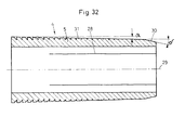
- FIG. 32 shows a further embodiment of the anchoring element 4.
- This anchoring member is again sleeve-shaped, corresponding to the anchoring member of the embodiment according to FIG. 3.
- a respective fastening element can be equipped with only one or then with several such anchoring members.
- the cross-sectional shape of the embodiment according to FIG. 32 may, for example, be any of the preceding cross-sectional shapes, which is described, for example, with reference to FIGS. 4-13.
- the shape of the outer shell shown corresponds to that of FIG. 4, whereby it is obviously to be noted that there are a large number of such projections 5 according to FIG. 4 in the longitudinal direction, so that the outer shell of the anchoring member 4 according to FIG. 32 extends at least along part its longitudinal extension is sawtooth-shaped, as indicated by reference number 31.
- the central hole i.e. the axial perforation of this sleeve-shaped anchoring member 4 is shown flat-walled. Obviously, it can also have a cross-sectional shape according to the above-mentioned embodiments, with this cross-sectional shape advantageously corresponding to that of the shaft 11 in all of the versions, as shown in FIGS. 14-18, so that the anchoring member 4 sits on the respective shaft 1 in a rotationally fixed manner.
- the embodiment in which the cross-sectional shape of the outer circumference of the anchoring member corresponds to that of its central hole and thus also to that of the shaft 1 has proven to be a particularly favorable embodiment.
- the embodiment according to FIG. 32 has an end section with an outer jacket section 30 which extends obliquely at an angle 5 relative to the longitudinal central axis, this angle s being larger water than the angle a, around which the outer jacket of the anchoring member 4 extends at an oblique angle to the longitudinal central axis 29.
Landscapes
- Engineering & Computer Science (AREA)
- General Engineering & Computer Science (AREA)
- Mechanical Engineering (AREA)
- Dowels (AREA)
- Joining Of Building Structures In Genera (AREA)
- Magnetic Resonance Imaging Apparatus (AREA)
- Ultra Sonic Daignosis Equipment (AREA)
- Measurement Of Velocity Or Position Using Acoustic Or Ultrasonic Waves (AREA)
- Transition And Organic Metals Composition Catalysts For Addition Polymerization (AREA)
- Superconductors And Manufacturing Methods Therefor (AREA)
- Slide Fasteners, Snap Fasteners, And Hook Fasteners (AREA)
Applications Claiming Priority (2)
| Application Number | Priority Date | Filing Date | Title |
|---|---|---|---|
| CH2104/90 | 1990-06-25 | ||
| CH2104/90A CH681648A5 (fr) | 1990-06-25 | 1990-06-25 |
Publications (2)
| Publication Number | Publication Date |
|---|---|
| EP0464574A1 true EP0464574A1 (fr) | 1992-01-08 |
| EP0464574B1 EP0464574B1 (fr) | 1995-01-11 |
Family
ID=4225970
Family Applications (1)
| Application Number | Title | Priority Date | Filing Date |
|---|---|---|---|
| EP91110412A Expired - Lifetime EP0464574B1 (fr) | 1990-06-25 | 1991-06-24 | Elément de fixation |
Country Status (8)
| Country | Link |
|---|---|
| US (1) | US5232322A (fr) |
| EP (1) | EP0464574B1 (fr) |
| JP (1) | JPH05106620A (fr) |
| AT (1) | ATE117055T1 (fr) |
| CH (1) | CH681648A5 (fr) |
| DE (1) | DE59104206D1 (fr) |
| FI (1) | FI913097A (fr) |
| NO (1) | NO912469L (fr) |
Cited By (5)
| Publication number | Priority date | Publication date | Assignee | Title |
|---|---|---|---|---|
| US5308205A (en) * | 1991-03-27 | 1994-05-03 | Mepla-Werke Lautenschlager Gmbh & Co. Kg | Plastic retaining peg, particularly for furniture fittings |
| EP0808696A1 (fr) * | 1996-05-24 | 1997-11-26 | HILTI Aktiengesellschaft | Système de fixation et procédé de réalisation de fixations |
| DE19628558A1 (de) * | 1996-07-16 | 1998-01-29 | Fischer Artur Werke Gmbh | Steckdübel |
| FR2931526A1 (fr) * | 2008-05-21 | 2009-11-27 | I D Plast Sas | Dispositif de fixation a frapper |
| WO2010133816A1 (fr) * | 2009-05-18 | 2010-11-25 | Wellmac Limited | Élément de fixation |
Families Citing this family (31)
| Publication number | Priority date | Publication date | Assignee | Title |
|---|---|---|---|---|
| GB9115850D0 (en) * | 1991-07-23 | 1991-09-04 | Univ Manchester | Coupling |
| SE469922B (sv) * | 1991-12-12 | 1993-10-11 | Karner & Co Ab | Anordning samt byxstång för permanent hopkoppling av två i en klädhängare ingående delar |
| US5415507A (en) * | 1993-07-29 | 1995-05-16 | Elco Industries, Inc. | Anchor with adjustable seal |
| US5549760A (en) * | 1994-12-01 | 1996-08-27 | White Consolidated Industries, Inc. | Mounting device for dishwasher insulation |
| CA2140475C (fr) * | 1995-01-18 | 2000-03-07 | Uli Walther | Vis |
| US5845911A (en) * | 1996-05-22 | 1998-12-08 | L&S Automotive Products Co. | Replacement split boot assembly |
| GB2328961B (en) * | 1997-09-06 | 2002-01-09 | Hydra Tools Internat Ltd | Point attack tooling system for mineral winning |
| US5909991A (en) * | 1997-11-24 | 1999-06-08 | Arrow Sign Company | Self adjusting plug |
| DE19922440A1 (de) * | 1999-05-06 | 2000-11-09 | Schaefer Micomed Gmbh | Pedikelschraube |
| US6350078B1 (en) * | 1999-09-24 | 2002-02-26 | The Torrington Company | Shaft depressor for a slap yoke in a steering assembly |
| DE19955684A1 (de) * | 1999-11-19 | 2001-05-23 | Hilti Ag | Ankerstange für Verankerungen mit organischen und/oder anorganischen Mörtelmassen |
| FR2810087B1 (fr) * | 2000-06-08 | 2004-07-23 | Legris Sa | Element pourvu exterieurement de moyens pour cooperer avec un taraudage |
| KR100863998B1 (ko) * | 2002-06-19 | 2008-10-16 | 삼성전자주식회사 | 액정표시모듈 및 이를 이용한 액정표시장치 |
| GB2400380A (en) * | 2003-04-09 | 2004-10-13 | Joseph Steven Kelly | Toilet seat fitting |
| EP1819929A1 (fr) * | 2003-10-30 | 2007-08-22 | Malgorzata Wesolowska | Broche de fixation |
| US20070134073A1 (en) * | 2005-12-14 | 2007-06-14 | Shereyk David A | Fastener |
| JP4895719B2 (ja) * | 2006-08-17 | 2012-03-14 | Ykk株式会社 | 連結具 |
| WO2008035413A1 (fr) * | 2006-09-20 | 2008-03-27 | Fujitsu Limited | Processeur d'informations et procédé de gestion d'informations |
| US7708512B2 (en) * | 2006-10-18 | 2010-05-04 | Newfrey Llc | Compression limiter |
| US7753633B2 (en) * | 2007-11-14 | 2010-07-13 | Newfrey Llc | Power seal bolt assembly |
| US7992900B2 (en) * | 2008-05-01 | 2011-08-09 | Reliable Racing Supply, Inc. | Pole anchor and ski pole base with extending brush bristles and acircular, preferably hexagonal, section |
| WO2009135679A1 (fr) * | 2008-05-09 | 2009-11-12 | Cristiano Malavasi | Organe de fixation pour verres |
| US8459920B2 (en) * | 2009-01-31 | 2013-06-11 | Stafast Products, Inc. | Fastener |
| DE102010034289A1 (de) * | 2010-08-13 | 2012-02-16 | Schaeffler Technologies Gmbh & Co. Kg | Unwuchtwelle und Verfahren zu deren Herstellung |
| DE102011001637B4 (de) * | 2011-03-29 | 2013-06-06 | Supair-Tel Ag | Beduftungsvorrichtung für ein Fahrzeug |
| KR101296671B1 (ko) * | 2011-07-29 | 2013-08-14 | 현대로템 주식회사 | 티타늄 파이프 용접구조물 열처리용 치공구 |
| US9610904B2 (en) * | 2012-08-13 | 2017-04-04 | Ford Global Technologies, Llc | Push pin with over-travel stop |
| US9862422B2 (en) * | 2016-02-26 | 2018-01-09 | Ford Global Technologies, Llc | Fastener for providing a clamp load between two parts |
| EP3239539A1 (fr) * | 2016-04-27 | 2017-11-01 | HILTI Aktiengesellschaft | Cheville a douille ondulee |
| US10870043B2 (en) * | 2019-05-22 | 2020-12-22 | Jack Cooper | Golf tee with reduced friction |
| CN114060379B (zh) * | 2021-11-16 | 2023-06-02 | 广东电网有限责任公司 | 一种开口销 |
Citations (5)
| Publication number | Priority date | Publication date | Assignee | Title |
|---|---|---|---|---|
| FR1369178A (fr) * | 1963-09-05 | 1964-08-07 | Procédé et dispositif d'ancrage applicable aux tiges de soutènement employées dans les mines, et pour tous autres scellements à sec | |
| DE2246833A1 (de) * | 1972-08-25 | 1974-03-07 | Owo Presswerk Ag | Befestigungsvorrichtung, insbesondere fuer closettabdeckungen |
| DE3333493A1 (de) * | 1983-09-16 | 1985-04-04 | Peter 2154 Apensen Möller | Selbstverspannender spreizanker |
| US4626139A (en) * | 1985-02-19 | 1986-12-02 | Russell Blackwell | Roof bolt anchor |
| GB2212581A (en) * | 1987-11-17 | 1989-07-26 | Dom Holdings Plc | Anchor bolt |
Family Cites Families (11)
| Publication number | Priority date | Publication date | Assignee | Title |
|---|---|---|---|---|
| US1572770A (en) * | 1923-06-27 | 1926-02-09 | John Q Roberts | Bolt lock |
| FR1259692A (fr) * | 1960-06-08 | 1961-04-28 | Illinois Tool Works | élément de fixation en matière plastique |
| FR1506796A (fr) * | 1968-12-16 | 1967-12-22 | Standard Pressed Steel Co | Dispositif de fixation de sécurité |
| DE2358479A1 (de) * | 1973-11-23 | 1975-06-05 | Gebhardt Kg Ludwig | Aus befestigungszapfen und huelse bestehende anschlusseinrichtung |
| US4391544A (en) * | 1974-12-16 | 1983-07-05 | Sps Technologies, Inc. | Self-retained fastener |
| DE2625182C3 (de) * | 1976-03-11 | 1980-06-19 | Richard Heinze Gmbh & Co Kg, 4900 Herford | Beschlag zum losbaren Verbinden von zwei Bauteilen, insbesondere plattenförmigen Bauteilen fur Möbel |
| FR2359309A1 (fr) * | 1976-07-20 | 1978-02-17 | Renault | Dispositif d'implantation d'une piece de liaison dans un trou d'une paroi mince |
| SU647465A1 (ru) * | 1977-02-07 | 1979-02-15 | Rakhmanov Nikolaj N | Неразьемное соединение деталей |
| US4129921A (en) * | 1978-01-05 | 1978-12-19 | Shepherd Products U.S. Inc. | Plastic grip ring |
| US4287807A (en) * | 1979-06-01 | 1981-09-08 | Usm Corporation | Pull-to-set anchoring device |
| GB2102057A (en) * | 1980-12-31 | 1983-01-26 | Kwikform Ltd | Fastening |
-
1990
- 1990-06-25 CH CH2104/90A patent/CH681648A5/de not_active IP Right Cessation
-
1991
- 1991-06-21 US US07/719,023 patent/US5232322A/en not_active Expired - Fee Related
- 1991-06-24 DE DE59104206T patent/DE59104206D1/de not_active Expired - Fee Related
- 1991-06-24 NO NO91912469A patent/NO912469L/no unknown
- 1991-06-24 EP EP91110412A patent/EP0464574B1/fr not_active Expired - Lifetime
- 1991-06-24 AT AT91110412T patent/ATE117055T1/de not_active IP Right Cessation
- 1991-06-25 FI FI913097A patent/FI913097A/fi not_active Application Discontinuation
- 1991-06-25 JP JP3153391A patent/JPH05106620A/ja not_active Withdrawn
Patent Citations (5)
| Publication number | Priority date | Publication date | Assignee | Title |
|---|---|---|---|---|
| FR1369178A (fr) * | 1963-09-05 | 1964-08-07 | Procédé et dispositif d'ancrage applicable aux tiges de soutènement employées dans les mines, et pour tous autres scellements à sec | |
| DE2246833A1 (de) * | 1972-08-25 | 1974-03-07 | Owo Presswerk Ag | Befestigungsvorrichtung, insbesondere fuer closettabdeckungen |
| DE3333493A1 (de) * | 1983-09-16 | 1985-04-04 | Peter 2154 Apensen Möller | Selbstverspannender spreizanker |
| US4626139A (en) * | 1985-02-19 | 1986-12-02 | Russell Blackwell | Roof bolt anchor |
| GB2212581A (en) * | 1987-11-17 | 1989-07-26 | Dom Holdings Plc | Anchor bolt |
Cited By (7)
| Publication number | Priority date | Publication date | Assignee | Title |
|---|---|---|---|---|
| US5308205A (en) * | 1991-03-27 | 1994-05-03 | Mepla-Werke Lautenschlager Gmbh & Co. Kg | Plastic retaining peg, particularly for furniture fittings |
| EP0808696A1 (fr) * | 1996-05-24 | 1997-11-26 | HILTI Aktiengesellschaft | Système de fixation et procédé de réalisation de fixations |
| US5836405A (en) * | 1996-05-24 | 1998-11-17 | Hilti Aktiengesellschaft | Fastening apparatus for and method of setting fastening elements |
| DE19628558A1 (de) * | 1996-07-16 | 1998-01-29 | Fischer Artur Werke Gmbh | Steckdübel |
| DE19628558C2 (de) * | 1996-07-16 | 1998-10-22 | Fischer Artur Werke Gmbh | Steckdübel |
| FR2931526A1 (fr) * | 2008-05-21 | 2009-11-27 | I D Plast Sas | Dispositif de fixation a frapper |
| WO2010133816A1 (fr) * | 2009-05-18 | 2010-11-25 | Wellmac Limited | Élément de fixation |
Also Published As
| Publication number | Publication date |
|---|---|
| JPH05106620A (ja) | 1993-04-27 |
| FI913097A (fi) | 1991-12-26 |
| NO912469L (no) | 1991-12-27 |
| CH681648A5 (fr) | 1993-04-30 |
| ATE117055T1 (de) | 1995-01-15 |
| NO912469D0 (no) | 1991-06-24 |
| FI913097A0 (fi) | 1991-06-25 |
| US5232322A (en) | 1993-08-03 |
| DE59104206D1 (de) | 1995-02-23 |
| EP0464574B1 (fr) | 1995-01-11 |
Similar Documents
| Publication | Publication Date | Title |
|---|---|---|
| EP0464574A1 (fr) | Elément de fixation | |
| DE19505311C2 (de) | Befestigungsanordnung von Beschlägen, insbesondere Möbelbeschlägen an Möbelstücken | |
| EP0794736B1 (fr) | Element de fixation osteosynthetique | |
| EP0799387B1 (fr) | Vis foreuse et taraudeuse et son procede de vissage | |
| DE2047185B2 (de) | Klemmverbindung insbesondere bei Bauwerken, Gerüsten o.dgl | |
| EP2191152B1 (fr) | Utilisation d'un rivet aveugle et procédé de placement d'un rivet aveugle | |
| DE2249762B2 (de) | Doppelt spreizender duebel | |
| EP2019214A2 (fr) | Elément destiné à être inséré à force dans un composant non percé ou percé et procédé de fabrication d'un tel élément | |
| EP0477713B1 (fr) | Dispositif pour fixer notamment une pièce de construction tubulaire à une paroi ou un élément similaire | |
| DE3523155A1 (de) | Verbindungselement fuer rohre | |
| CH505305A (de) | Einrastverbindung | |
| WO2008012051A1 (fr) | Vis destinée à former des trous et des filets | |
| DE102007027831B4 (de) | Dübel für eine Deckplatteneinspreizung | |
| EP1573214A1 (fr) | Rivet auto-poinconneur | |
| DE19607446A1 (de) | Schlagdübel | |
| DE3816662A1 (de) | Rohrduebel zum einsetzen in ein bohrloch | |
| EP1183474B1 (fr) | Dispositif de fixation permettant de fixer des éléments de construction à des parties de meuble, ou des parties de meubles entre elles | |
| DE102012107009A1 (de) | Dübel | |
| EP0551629B1 (fr) | Cheville à expansion | |
| EP0760429B1 (fr) | Cheville d'expansion en matière plastique | |
| EP0572598B1 (fr) | Rivet aveugle tirant autoforeur | |
| DE4409403C2 (de) | Dübel mit Spreizkörper | |
| EP0058709A1 (fr) | Boulon d'ancrage | |
| EP3872356B1 (fr) | Système de raccordement d'une partie de meuble | |
| DE2542074C3 (de) | Weichstein-Spreizdubel |
Legal Events
| Date | Code | Title | Description |
|---|---|---|---|
| PUAI | Public reference made under article 153(3) epc to a published international application that has entered the european phase |
Free format text: ORIGINAL CODE: 0009012 |
|
| AK | Designated contracting states |
Kind code of ref document: A1 Designated state(s): AT BE CH DE DK ES FR GB IT LI LU NL SE |
|
| 17P | Request for examination filed |
Effective date: 19920203 |
|
| 17Q | First examination report despatched |
Effective date: 19921111 |
|
| GRAA | (expected) grant |
Free format text: ORIGINAL CODE: 0009210 |
|
| AK | Designated contracting states |
Kind code of ref document: B1 Designated state(s): AT BE CH DE DK ES FR GB IT LI LU NL SE |
|
| PG25 | Lapsed in a contracting state [announced via postgrant information from national office to epo] |
Ref country code: IT Free format text: LAPSE BECAUSE OF FAILURE TO SUBMIT A TRANSLATION OF THE DESCRIPTION OR TO PAY THE FEE WITHIN THE PRE;WARNING: LAPSES OF ITALIAN PATENTS WITH EFFECTIVE DATE BEFORE 2007 MAY HAVE OCCURRED AT ANY TIME BEFORE 2007. THE CORRECT EFFECTIVE DATE MAY BE DIFFERENT FROM THE ONE RECORDED.SCRIBED TIME-LIMIT Effective date: 19950111 Ref country code: DK Effective date: 19950111 Ref country code: NL Effective date: 19950111 Ref country code: BE Effective date: 19950111 Ref country code: GB Effective date: 19950111 Ref country code: FR Effective date: 19950111 Ref country code: ES Free format text: THE PATENT HAS BEEN ANNULLED BY A DECISION OF A NATIONAL AUTHORITY Effective date: 19950111 |
|
| REF | Corresponds to: |
Ref document number: 117055 Country of ref document: AT Date of ref document: 19950115 Kind code of ref document: T |
|
| REF | Corresponds to: |
Ref document number: 59104206 Country of ref document: DE Date of ref document: 19950223 |
|
| PG25 | Lapsed in a contracting state [announced via postgrant information from national office to epo] |
Ref country code: SE Effective date: 19950411 |
|
| EN | Fr: translation not filed | ||
| NLV1 | Nl: lapsed or annulled due to failure to fulfill the requirements of art. 29p and 29m of the patents act | ||
| PG25 | Lapsed in a contracting state [announced via postgrant information from national office to epo] |
Ref country code: AT Effective date: 19950624 |
|
| PG25 | Lapsed in a contracting state [announced via postgrant information from national office to epo] |
Ref country code: CH Effective date: 19950630 Ref country code: LI Effective date: 19950630 Ref country code: LU Free format text: LAPSE BECAUSE OF NON-PAYMENT OF DUE FEES Effective date: 19950630 |
|
| GBV | Gb: ep patent (uk) treated as always having been void in accordance with gb section 77(7)/1977 [no translation filed] |
Effective date: 19950111 |
|
| PLBE | No opposition filed within time limit |
Free format text: ORIGINAL CODE: 0009261 |
|
| STAA | Information on the status of an ep patent application or granted ep patent |
Free format text: STATUS: NO OPPOSITION FILED WITHIN TIME LIMIT |
|
| 26N | No opposition filed | ||
| REG | Reference to a national code |
Ref country code: CH Ref legal event code: PL |
|
| PG25 | Lapsed in a contracting state [announced via postgrant information from national office to epo] |
Ref country code: DE Effective date: 19960301 |