EP0464436B1 - Zyklonbrenner mit zylindrischer Brennkammer - Google Patents
Zyklonbrenner mit zylindrischer Brennkammer Download PDFInfo
- Publication number
- EP0464436B1 EP0464436B1 EP91109846A EP91109846A EP0464436B1 EP 0464436 B1 EP0464436 B1 EP 0464436B1 EP 91109846 A EP91109846 A EP 91109846A EP 91109846 A EP91109846 A EP 91109846A EP 0464436 B1 EP0464436 B1 EP 0464436B1
- Authority
- EP
- European Patent Office
- Prior art keywords
- combustion chamber
- gas
- burner according
- cyclonic burner
- outlet slit
- Prior art date
- Legal status (The legal status is an assumption and is not a legal conclusion. Google has not performed a legal analysis and makes no representation as to the accuracy of the status listed.)
- Expired - Lifetime
Links
Images


Classifications
-
- F—MECHANICAL ENGINEERING; LIGHTING; HEATING; WEAPONS; BLASTING
- F23—COMBUSTION APPARATUS; COMBUSTION PROCESSES
- F23C—METHODS OR APPARATUS FOR COMBUSTION USING FLUID FUEL OR SOLID FUEL SUSPENDED IN A CARRIER GAS OR AIR
- F23C3/00—Combustion apparatus characterised by the shape of the combustion chamber
- F23C3/006—Combustion apparatus characterised by the shape of the combustion chamber the chamber being arranged for cyclonic combustion
Definitions
- the invention relates to a cyclone burner with a cylindrical combustion chamber, as specified in the preamble of claim 1.
- Exit openings in the combustion chamber wall are known for the exit of solid particles from a cylindrical combustion chamber, US Pat. No. 3,357,383. Some of the solid particles located directly on the combustion chamber wall can be removed from the combustion chamber via these outlet openings. Inserts corresponding to a combustion grate for removing ash from a cyclone burner are described in DE-PS 10 24 663, a cyclone burner with vertically arranged axis and deduction of the solid particles from funnel-shaped soil is known from DE-PS 974 562.
- EP-A-0 271 642 discloses a cyclone burner with a cylindrical combustion chamber for burning a fuel gas / air mixture introduced tangentially into the combustion chamber.
- outlet slots for solid particles carried by the fuel gas are provided, which collide with wall steps that are located behind the outlet slots as seen in the flow direction of the fuel gas / air mixture and stand out from the jacket towards the interior of the combustion chamber and into through the outlet slots get an ash room.
- the separation is only partially successful.
- particles can also be thrown back into the interior of the combustion chamber when hitting the wall steps instead of passing through the outlet slots.
- the object of the invention is to provide a cyclone burner with a rapid and as complete as possible separation possibility for the solid particles located in the area of the combustion chamber near the wall.
- the wall step is formed by a boundary surface of the outlet slot, the height of the wall step simultaneously determining the opening width of the outlet slot.
- the wall step height is adapted to the particle fraction to be removed from the combustion chamber.
- the wall step is thus open at the end of the solid particles for entry and the opening width of the formed outlet slot is given by the wall step height (height of the open end wall) measured in the radial direction, which then also determines the particle fraction that can be removed from the combustion chamber.
- the wall step is adjustable, claim 2.
- a complete separation of the solid particles separating out in the combustion chamber is supported according to claim 3 in that the outlet slot in the cylindrical jacket extends over its entire width. So that the solid particles from the combustion chamber can enter the separation chamber unhindered, the outlet slit has a flow cross-section that widens outwards in a wedge shape, claim 4.
- a negative pressure is generated in relation to the pressure in the combustion chamber.
- a bypass line leading from the separating space to the exhaust line is preferably used for this purpose. The vacuum is set by an adjustable throttle valve in the bypass line, claim 6.
- Figures 1 to 3 show cyclone burners with cylindrical combustion chambers 1, the combustion chamber axes 2 are arranged horizontally.
- a gas supply 3 for a fuel gas / air mixture In the exemplary embodiment, the gas supply 3 has two flow spaces 5, 6 separated from one another by a partition 4, through which fuel gas in the flow space 5 and air in the flow space 6 are introduced into the combustion chamber 1.
- the fuel gas / air mixture that forms in the upper region of the combustion chamber is ignited at the start of the cyclone burner via a pilot burner 7.
- the pilot burner 7 is inserted into the combustion chamber 1 through the jacket 8 thereof. With the pilot burner 7, the combustion chamber 1 can also be preheated to a suitable ignition temperature before the entry of fuel gas and air, at which the fuel gas / air mixture is combustible from the time of ignition with formation of only small amounts of harmful gas.
- the exhaust gas formed in the combustion chamber 1 flows out via an exhaust gas line 9 with line parts 9a, 9b.
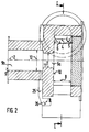
- the exhaust pipe 9 is connected to the front of the combustion chamber 1, in the exemplary embodiment on a front 10 centrally and parallel to the combustion chamber axis 2.
- the part 9a of the exhaust gas line 9, which forms the connection of the exhaust gas line to an end face 10 of the combustion chamber 1, has a narrower flow cross section 11 than the part 9b of the exhaust gas line 9 with a flow cross section 12.
- the part 9a can be designed in the form of a nozzle, the Flow cross-section 11 from the connection of the exhaust gas line starting from the end face 10 to the mouth of part 9a in part 9b expanded like a Laval nozzle. This accelerates and stabilizes the exhaust gas flow from the combustion chamber 1, with a mixing effect for the burnout at the same time of the exhaust gas is reached.
- the exhaust gas flows through part 9b to a heat exchanger not shown in the drawing.
- the outlet slot 13 In the lower area of the combustion chamber 1 there is an outlet slot 13 for the discharge of solid particles which are introduced into the combustion chamber 1 with the fuel gas. The solid particles fall via the outlet slot into a separating space 14 into which the outlet slot opens.
- the separating space has a closable opening 14a for ash removal from the separating space.
- the outlet slot 13 extends over the entire width B of the combustion chamber 1, see FIG. 2, and is formed by a wall step 15, the end face of which is open to the entry of solid particles.
- the outlet slot 13 has a flow cross section 16 which widens outwards in the jacket 8, the outlet slot widens outwards in a wedge shape.
- the wall step 15 is formed by a boundary surface 17, which is arranged at an angle to an opposite radially extending boundary surface 18 of the outlet slot 13.
- the formation of the wall step 15, in particular the wall step height 19 with which the wall step projects into the combustion chamber 1, and the wedge-shaped widening of the outlet slot determine the solid particle fraction which is discharged into the separation chamber 14 via the outlet slot 13.
- the wall step height 19 of the wall step is adjustable.
- a wall step 15a is designed as a flap and movable about an axis 20. It can be rotated on the combustion chamber wall in accordance with the desired particle separation. Since the solid particles concentrate on the inside of the jacket due to the centrifugal forces acting on them, the thicker the gas layer carrying the particles, the more the wall step 15a can be led into the free combustion chamber space. However, the position of the wall step 15a also influences the optimal combustion process in the combustion chamber, it must be regulated accordingly.
- the outlet slot 13 runs in the jacket 8 at an angle 21 to the radial plane 22 of the combustion chamber 1. The angle 21 is dimensioned such that the particles emerge from the combustion chamber with as little resistance as possible.
- the outlet slot 13 has a uniform flow cross section 16a.
- a combustible gas mixture already enters the combustion chamber 1 via the gas supply 3.
- a control flap 24 is arranged in the mouth area 23 of the gas supply 3.
- the position of the control flap 24 is changed with the aim of changing the gas inlet cross section, with the aim of making it constant
- the entry velocity also influences the burnout of the gas mixture in the combustion chamber.
- combustion chamber 1 according to FIG. 3 is constructed in the same way as the combustion chamber according to the embodiment according to FIGS. 1 and 2.
- the same reference numerals as in FIGS. 1 and 2 were therefore used in FIG. 3.
- a bypass 25 leads from the separating space 14 to the exhaust gas line 9. It opens into part 9b of the exhaust gas line.
- a throttle valve 26 is used, the position of which allows the desired negative pressure in the separating chamber 14 to be set relative to the pressure in the combustion chamber 1. The resulting pressure difference between combustion chamber 1 and separation chamber 14 influences the desired separation of the solid particles.
- baffle plates 27 are used in the exemplary embodiment according to FIG. 1 in the separating space 14 of the cyclone burner, which hold back the solid particles in the separating space.
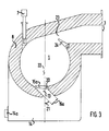
- FIGS. 4 and 5 show a cyclone burner whose combustion chamber axis 28 is arranged vertically.
- fuel gas and air are tangentially into a combustion chamber from the side 29 introduced via a fuel gas inlet 30 and an air line 31.
- solid particles enter the combustion chamber 29 into the combustion chamber, which are preferably discharged from the combustion chamber 29 via an outlet slot 34 which is offset approximately 225 ° from the access 32 in the jacket 33 of the combustion chamber.
- an adjustable wall step 15b is attached to the outlet slot 34.
- the solid particles emerge via the wall step 15b in a separating space 35 which is cylindrical in the same way as the combustion chamber 29 and also has an axis arranged vertically.
- the axis of the separating space 35 coincides with the combustion chamber axis 28 in the exemplary embodiment, the combustion chamber 29 is thus arranged centrally in the separating space 35.
- the combustion chamber 29 has a chamber base 36 that slopes conically from its center toward the jacket 33.
- passage openings for the solid particles are also provided in the bottom. The passage openings are not shown in FIG. 5.
- the exhaust gas flows out of the combustion chamber 29 centrally.
- Flow arrows 37 are shown schematically in FIG. 5 for the exhaust gas flow.
- the hot exhaust gas is discharged within an exhaust gas line 38; in the exemplary embodiment, the exhaust gas line is connected to a heat exchanger (not shown in FIG. 5), via which the hot exhaust gas releases its heat to a heating medium.
- the exhaust line 38 is open to the separation space 35.
- the gas entering the separation chamber 35 when the solid particles are removed from the combustion chamber 29 can thus also be drawn off together with the exhaust gas directly via the exhaust line 38.
- a flue gas recirculation 39 is also connected to the separating space 35, the access of which can be opened by means of an adjusting flap 40.
- the amount of gas returned through the flue gas recirculation is regulated by adjusting the opening width of the control flap 40 accordingly.
- a solid lock 42 is provided for emptying the separating space, which is opened for discharge depending on the amount of solid.
- the central position of the combustion chamber 29 within the separating space 35 and the free flow deflection of the exhaust gas in the ceiling area of the separating space serve to largely clean the hot exhaust gas withdrawing from the combustion chamber before entering the heat exchanger. Solid particles introduced into the combustion chamber by the fuel gas / air mixture are separated in the separation room according to the desired requirements. A clogging of the heat exchanger with dust is thus sufficiently prevented in the cyclone burner according to the invention.
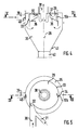
- FIG. 6 shows a further combustion chamber with a horizontal combustion chamber axis in cross section.
- This combustion chamber differs from the combustion chamber shown in FIGS. 1 and 2 essentially by a second particle outlet slot: in addition to a lower particle outlet slot 43 with wall step 44, which projects into the combustion chamber towards the interior 45, there is another particle outlet slot in the inlet area of the combustion gas and combustion air 46 arranged with wall step 47.
- the wall step 47 has a height 19 which lifts off from the wall side 48 of the interior 45.
- the particles entering the combustion chamber with the fuel gases are thus discharged from the combustion chamber at two points, the coarse particle fraction being discharged essentially via the particle outlet slot 46 and the finer fraction via the particle outlet slot 43.
- the heights 19 of the wall steps 44 and 47 can also be dimensioned and designed differently in accordance with the desired degree of separation in the combustion chamber.
- combustion air and fuel gas at the gas supply 3 still enter the combustion chamber separately, the combustion air via an air duct 49 opening at the gas supply 3, and the fuel gas via a fuel gas inlet duct 50.
- the combustion chamber according to FIG. 6 functions in the same way as the combustion chamber shown in FIGS. 1 and 2. Identically designed and functionally retained device parts are therefore marked in FIG. 6 with the same reference numerals as in the aforementioned figures.
Landscapes
- Engineering & Computer Science (AREA)
- Chemical & Material Sciences (AREA)
- Combustion & Propulsion (AREA)
- Mechanical Engineering (AREA)
- General Engineering & Computer Science (AREA)
- Cyclones (AREA)
- Sampling And Sample Adjustment (AREA)
- Incineration Of Waste (AREA)
- Combustion Of Fluid Fuel (AREA)
- Gasification And Melting Of Waste (AREA)
Description
- Die Erfindung bezieht sich auf einen Zyklonbrenner mit zylindrischer Brennkammer, wie im Oberbegriff des Patentanspruches 1 angegeben.
- Bei Brennkammern, denen als Brennstoffe in einem Feststoffvergaser erzeugte Gasgemische zugeführt werden, ist damit zu rechnen, daß mit den Brenngasen auch Feststoffpartikeln eingeführt werden, die sich in der Brennkammer absetzen. Dies ist insbesondere der Fall, wenn die Brennkammer unmittelbar am Gasausgang des Feststoffvergasers angeschlossen ist. Nachteilig sind vor allem vom Brenngas mitgerissene unverbrennbare Inertstoffpartikeln, die aus der Brennkammer abgetrennt werden müssen, bevor das in der Brennkammer erzeugte heiße Abgas in einen nachgeschalteten Wärmetauscher einströmt. Es muß vermieden werden, daß sich der Wärmetauscher durch sich absetzende Feststoffpartikeln zusetzt.
- Zum Austritt von Feststoffpartikeln aus einer zylindrischen Brennkammer sind Austrittsöffnungen in der Brennkammerwand bekannt, US-PS 3,357,383. Über diese Austrittsöffnungen kann ein Teil der sich unmittelbar an der Brennkammerwand befindlichen Feststoffpartikeln aus der Brennkammer entfernt werden. Einem Feuerungsrost entsprechende Einsätze zum Abführen von Asche aus einem Zyklonbrenner werden in DE-PS 10 24 663 beschrieben, ein Zyklonbrenner mit senkrecht angeordneteter Achse und Abzug der Feststoffartikeln von trichterförmigem Boden ist aus DE-PS 974 562 bekannt.
- Aus EP-A-0 271 642 ist ein Zyklonbrenner mit zylindrischer Brennkammer zur Verbrennung eines tangential in die Brennkammer eingeführten Brenngas/Luft-Gemisches bekannt. Im Mantel der Brennkammer sind Austrittsschlitze für vom Brenngas mitgeführte Feststoffpartikeln vorgesehen, die auf Wandstufen, die in Strömungsrichtung des Brenngas/Luft-Gemisches gesehen hinter den Austrittsschlitzen angebracht sind und sich zum Innenraum der Brennkammer hin vom Mantel abheben, aufprallen und durch die Austrittsschlitze hindurch in einen Ascheraum gelangen. Je nach abzuscheidender Partikelfraktion gelingt das Abscheiden jedoch nur teilweise. Insbesondere können Partikel beim Aufprallen auf die Wandstufen statt durch die Austrittsschlitze hindurchzutreten, auch zurück in den Innenraum der Brennkammer geschleudert werden.
- Aufgabe der Erfindung ist es, bei einem Zyklonbrenner eine rasche und möglichst vollständige Abtrennmöglichkeit für die sich im wandnahen Bereich der Brennkammer befindenden Feststoffpartikeln zu schaffen.
- Gelöst wird diese Aufgabe bei einem Zyklonbrenner der eingangs genannten Art durch die in Patentanspruch 1 angegebenen Merkmale. Die Wandstufe wird von einer Begrenzungsfläche des Austrittsschlitzes gebildet, wobei die Höhe der Wandstufe zugleich die Öffnungsweite des Austrittschlitzes bestimmt. Die Wandstufenhöhe wird der aus der Brennkammer abzuführenden Partikelfraktion angepaßt. Die Wandstufe ist somit zum Eintritt der Feststoffpartikeln an Ihrer Stirnseite geöffnet und die Öffnungsweite des ausgebildten Austrittsschlitzes ist durch die in radialer Richtung bemessene Wandstufenhöhe (Höhe der geöffneten Stirnwand) gegeben, die dann auch die aus der Brennkammer abführbare Partikelfraktion bestimmt. Zur Steuerung des gewünschten Austritts der Partikeln ist die Wandstufe verstellbar ausgeführt, Patentanspruch 2.
- Eine vollständige Abtrennung der sich in der Brennkammer abscheidenden Feststoffpartikeln wird nach Patentanspruch 3 dadurch unterstützt, daß sich der Austrittsschlitz im zylindrischen Mantel über dessen gesamter Breite erstreckt. Damit die Feststoffpartikeln aus der Brennkammer in den Abscheideraum ungehindert eintreten können, weist der Austrittsschlitz einen sich nach außen keilförmig erweiternden Strömungsquerschnitt auf, Patentanspruch 4. Im Abscheideraum wird ein Unterdruck gegenüber dem Druck in der Brennkammer erzeugt. Bevorzugt dient dazu nach Patentanspruch 5 eine vom Abscheideraum zur Abgasleitung geführte Bypaßleitung. Der Unterdruck wird durch eine verstellbare Drosselklappe in der Bypaßleitung eingestellt, Patentanspruch 6.
- Die Erfindung und weitere Ausgestaltungen der Erfindung werden nachfolgend anhand von Ausführungsbeispielen näher erläutert, die in der Zeichnung schematisch wiedergegeben sind. Die Zeichnung zeigt im einzelnen:
- Figur 1
- Querschnitt einer Zyklonbrennkammer mit waagerecht angeordneter Brennkammerachse und mit Brenngaseintritt im oberen und Partikelaustritt im unteren Kammerbereich gemäß Schnittlinie I/I nach Figur 2;
- Figur 2
- Längsschnitt einer Brennkammer gemäß Figur 1 nach Schnittlinie II/II;
- Figur 3
- Querschnitt einer Zyklonbrennkammer mit verstellbarer Wandstufe;
- Figur 4
- Querschnitt einer Zyklonbrennkammer mit senkrechter Brennkammerachse und seitlichem Brenngaseintritt und seitlichem Partikelaustritt gemäß Schnittlinie IV/IV nach Figur 5;
- Figur 5
- Längsschnitt einer Brennkammer gemäß Figur 4 nach Schnittlinie V/V;
- Figur 6
- Querschnitt einer Zyklonkammer mit waagerecht angeordneter Brennkammerachse und zwei Partikelaustrittsschlitzen.
- Die Figuren 1 bis 3 zeigen Zyklonbrenner mit zylindrischen Brennkammern 1, deren Brennkammerachsen 2 waagerecht angeordnet sind. Beim Zyklonbrenner nach Figuren 1 und 2 mündet im oberen Bereich der waagerecht liegenden Brennkammer 1 eine Gaszufuhr 3 für ein Brenngas/Luft-Gemisch. Im Ausführungsbeispiel weist die Gaszufuhr 3 zwei voneinander durch eine Trennwand 4 getrennte Strömungsräume 5,6 auf, durch die im Strömungsraum 5 Brenngas und im Strömungsraum 6 Luft in die Brennkammer 1 eingeleitet werden. Das sich hierbei im oberen Bereich der Brennkammer bildende Brenngas/ Luft-Gemisch wird beim Start des Zyklonbrenners über einen Zündbrenner 7 gezündet. Der Zündbrenner 7 ist in die Brennkammer 1 durch deren Mantel 8 hindurch eingeführt. Mit dem Zündbrenner 7 läßt sich die Brennkammer 1 auch vor Eintritt von Brenngas und Luft auf eine geeignete Zündtemperatur vorwärmen, bei der das Brenngas/Luft-Gemisch schon vom Zündzeitpunkt an unter Ausbildung nur geringer Schadgasanteile verbrennbar ist.
- Das in der Brennkammer 1 gebildete Abgas strömt über eine Abgasleitung 9 mit Leitungsteilen 9a, 9b ab. Die Abgasleitung 9 ist an der Brennkammer 1 stirnseitig, im Ausführungsbeispiel an einer Stirnseite 10 zentral und parallel zur Brennkammerachse 2 verlaufend angeschlossen. Der Teil 9a der Abgasleitung 9, der den Anschluß der Abgasleitung an einer Stirnseite 10 der Brennkammer 1 bildet, weist einen engeren Strömungsquerschnitt 11 auf, als der Teil 9b der Abgasleitung 9 mit Strömungsquerschnitt 12. Der Teil 9a kann düsenformig ausgebildet sein, wobei sich der Strömungsquerschnitt 11 vom Anschluß der Abgasleitung von der Stirnseite 10 ausgehend bis zur Mündung des Teils 9a in den Teil 9b lavaldüsenartig erweitert. Dies beschleunigt und stabilisiert den Abgasstrom aus der Brennkammer 1, wobei zugleich ein Durchmischungseffekt für den Ausbrand des Abgases erreicht wird. Durch den Teil 9b strömt das Abgas zu einem in der Zeichnung nicht wiedergegebenen Wärmetauscher ab.
- Im unteren Bereich der Brennkammer 1 ist ein Austrittsschlitz 13 zur Ableitung von Feststoffpartikeln vorgesehen, die in die Brennkammer 1 mit dem Brenngas eingeführt werden. Über den Austrittsschlitz fallen die Feststoffpartikeln in einen Abscheideraum 14, in den der Austrittsschlitz mündet. Der Abscheideraum weist eine verschließbare Öffnung 14a zur Entaschung des Abscheideraums auf. Der Austrittsschlitz 13 dehnt sich im Ausführungsbeispiel über die gesamte Breite B der Brennkammer 1 aus, siehe Figur 2, und wird von einer Wandstufe 15 gebildet, deren Stirnseite zum Eintritt von Feststoffpartikeln geöffnet ist. Der Austrittsschlitz 13 weist im Ausführungsbeispiel nach Figuren 1 und 2 einen sich im Mantel 8 nach außen erweiternden Strömungsquerschnitt 16 auf, der Austrittsschlitz erweitert sich nach außen keilförmig. Die Wandstufe 15 wird hierzu von einer Begrenzungsfläche 17 gebildet, die zu einer ihr gegenüberliegenden radial verlaufenden Begrenzungsfläche 18 des Austrittsschlitzes 13 im Winkel geneigt angeordnet ist. Von der Ausbildung der Wandstufe 15, insbesondere von deren Wandstufenhöhe 19, mit der die Wandstufe in die Brennkammer 1 hineinragt, und von der keilförmigen Erweiterung des Austrittsschlitzes wird die Feststoffpartikelfraktion bestimmt, die über den Austrittsschlitz 13 in den Abscheideraum 14 abgeführt wird. Je höher die Wandstufe 15 bemessen ist, um so mehr Feststoffpartikeln lassen sich aus der Brennkammer 1 hinaus in den Abscheideraum 14 leiten.
- In Figur 3 ist die Wandstufenhöhe 19 der Wandstufe verstellbar eingerichtet. Eine Wandstufe 15a ist als Klappe ausgebildet und um eine Achse 20 beweglich. Sie kann entsprechend der gewünschten Partikelabscheidung an der Brennkammerwand gedreht werden. Da sich die Feststoffpartikeln infolge der auf sie einwirkenden Zentrifugalkräfte an der Innenseite des Mantels konzentrieren, kann die Wandstufe 15a je stärker in den freien Brennkammerraum hineingeführt werden, je dicker die Partikeln führende Gasschicht ist. Die Stellung der Wandstufe 15a beeinflußt jedoch auch den optimalen Verbrennungsablaufs in der Brennkammer, sie ist entsprechend zu regulieren. Der Austrittsschlitz 13 verläuft im Ausführungsbeispiel nach Figur 3 im Mantel 8 in einem Winkel 21 zur Radialebene 22 der Brennkammer 1. Der Winkel 21 ist derart bemessen, daß die Partikeln aus der Brennkammer mit möglichst geringem Widerstand austreten. Der Austrittsschlitz 13 weist einen gleichförmigen Strömungsquerschnitt 16a auf.
- Im Ausführungsbeispiel nach Figur 3 tritt in die Brennkammer 1 über die Gaszufuhr 3 bereits ein brennbares Gasgemisch ein. Die Trennwand 4 und die getrennten Strömungsräume 5, 6, wie sie im Ausführungsbeispiel nach Figuren 1 und 2 vorhanden sind, sind entfallen. Zur Regelung der Zufuhr des Gasgemisches, insbesondere zur Regelung der Einströmgeschwindigkeit des Gasgemisches in die Brennkammer, ist im Mündungsbereich 23 der Gaszufuhr 3 eine Regelklappe 24 angeordnet. Je nach Gasmenge, die entsprechend der gewünschten Wärmeerzeugungsleistung in die Brennkammer einzuführen ist, wird zur Veränderung des Gaseintrittsquerschnitts die Stellung der Regelklappe 24 mit dem Ziel verändert, eine konstante Eintrittsgeschwindigkeit für das brennbare Gasgemisch zu erreichen. Die Eintrittsgeschwindigkeit beeinflußt neben der Partikelabscheidung auch den Ausbrand des Gasgemisches in der Brennkammer.
- Im übrigen ist die Brennkammer 1 nach Figur 3 in gleicher Weise wie die Brennkammer nach dem Ausführungsbeispiel gemäß Figuren 1 und 2 aufgebaut. Für die gegenüber diesem Beispiel unverändert gebliebenen Teile der Brennkammer wurden deshalb in Figur 3 die gleichen Bezugszeichen wie in den Figuren 1 und 2 benutzt.
- Vom Abscheideraum 14 führt ein Bypass 25 zur Abgasleitung 9. Er mündet im Teil 9b der Abgasleitung. Im Bypass ist eine Drosselklappe 26 eingesetzt, über deren Stellung sich der im Abscheideraum 14 gewünschte Unterdruck gegenüber dem Druck in der Brennkammer 1 einstellen läßt. Die sich daraus ergebende Druckdifferenz zwischen Brennkammer 1 und Abscheideraum 14 beeinflußt die gewünschte Abscheidung der Feststoffpartikeln.
- Um ein Mitreißen der Feststoffpartikeln aus dem Abscheideraum 14 über den Bypass 25 in die Abgasleitung 9 zu vermeiden und im Abscheideraum die Partikelbewegung zu beruhigen, sind im Ausführungsbeispiel nach Figur 1 im Abscheideraum 14 des Zyklonbrenners Prallbleche 27 eingesetzt, die die Feststoffpartikeln im Abscheideraum zurückhalten.
- In Figuren 4 und 5 ist ein Zyklonbrenner wiedergegeben, dessen Brennkammerachse 28 senkrecht angeordnet ist. Bei diesem Zyklonbrenner wird Brenngas und Luft von der Seite her tangential in eine Brennkammer 29 über einen Brenngaseintritt 30 und eine Luftleitung 31 eingeführt. Am Zugang 32 des Brenngas/Luft-Gemisches treten zusammen mit dem Gasgemisch in die Brennkammer 29 Feststoffpartikeln ein, die aus der Brennkammer 29 bevorzugt über einen etwa um 225° gegenüber dem Zugang 32 im Mantel 33 der Brennkammer versetzt angeordneten Austrittsschlitz 34 abgeführt werden. Am Austrittsschlitz 34 ist hierzu eine verstellbare Wandstufe 15b angebracht.
- Über die Wandstufe 15b treten die Feststoffpartikeln in einen in gleicher Weise wie die Brennkammer 29 zylindrisch geformten Abscheideraum 35 mit ebenfalls senkrecht angeordneter Achse aus. Die Achse des Abscheideraums 35 fällt im Ausführungsbeispiel mit der Brennkammerachse 28 zusammen, die Brennkammer 29 ist somit zentral im Abscheideraum 35 angeordnet.
- Die Brennkammer 29 weist im Ausführungsbeispiel einen von ihrem Zentrum zum Mantel 33 hin kegelförmig abfallenden Kammerboden 36 auf. Zur Entnahme von mitgeführten Feststoffpartikeln, die sich am Kammerboden der Brennkammer sammeln, sind auch im Boden Durchtrittsöffnungen für die Feststoffpartikeln vorgesehen. Die Durchtrittsöffnungen sind in Figur 5 nicht dargestellt.
- Das Abgas strömt aus der Brennkammer 29 zentral ab. In Figur 5 sind schematisch für den Abgasstrom Strömungspfeile 37 eingezeichnet. Das heiße Abgas wird innerhalb einer Abgasleitung 38 abgeführt, im Ausführungsbeispiel ist die Abgasleitung mit einem in Figur 5 nicht wiedergegebenen Wärmetauscher verbunden, über den das heiße Abgas seine Wärme an ein Heizmedium abgibt.
- Die Abgasleitung 38 ist zum Abscheideraum 35 hin geöffnet. Das in den Abscheideraum 35 beim Abzug der Feststoffpartikeln aus der Brennkammer 29 eindringende Gas kann somit gemeinsam mit dem Abgas ebenfalls unmittelbar über die Abgasleitung 38 abziehen. Am Abscheideraum 35 ist zusätzlich eine Rauchgasrückführung 39 angeschlossen, deren Zugang mittels einer Stellklappe 40 geöffnet werden kann. Die jeweils über die Rauchgasrückführung zurückgeführte Gasmenge wird durch entsprechendes Einstellen der Öffnungsweite der Stellklappe 40 geregelt.
- Im unteren Bereich des Abscheideraums 35 befindet sich zum Abzug der abgeschiedenen Feststoffpartikeln ein trichterförmiger Partikelaustrag 41. Im Ausführungsbeispiel ist zur Entleerung des Abscheideraums eine Feststoffschleuse 42 vorgesehen, die zum Austrag je nach Feststoffanfall geöffnet wird.
- Die zentrale Lage der Brennkammer 29 innerhalb des Abscheideraums 35 und die freie Strömungsumlenkung des Abgases im Deckenbereich des Abscheideraums (siehe Strömungspfeile 37) dienen einer weitgehenden Reinigung des aus der Brennkammer abziehenden heißen Abgases vor Eintritt in den Wärmetauscher. Vom Brenngas/Luft-Gemisch in die Brennkammer eingeführte Feststoffpartikeln werden im Abscheideraum den gewünschten Anforderungen entsprechend abgeschieden. Ein Zusetzen des Wärmetauschers mit Staub ist somit beim Zyklonbrenner gemäß der Erfindung in ausreichendem Maße verhindert.
- In Figur 6 ist eine weitere Brennkammer mit waagerechter Brennkammerachse im Querschnitt dargestellt. Von der in Figuren 1 und 2 gezeigten Brennkammer unterscheidet sich diese Brennkammer im wesentlichen durch einen zweiten Partikelaustrittsschlitz: Neben einem unteren Partikelaustrittsschlitz 43 mit Wandstufe 44, die zum Innenraum 45 hin gerichtet in die Brennkammer hineinragt, ist im Eintrittsbereich von Brenngas und Verbrennungsluft ein weiterer Partikelaustrittsschlitz 46 mit Wandstufe 47 angeordnet. Die Wandstufe 47 weist in gleicher Weise wie die Wandstufe 44 eine sich zum Innenraum 45 von dessen Wandseite 48 abhebende Höhe 19 auf. Im Ausführungsbeispiel nach Figur 6 werden die mit den Brenngasen in die Brennkammer eintretenden Partikel somit an zwei Stellen aus der Brennkammer ausgeschleust, wobei die grobere Partikelfraktion im wesentlichen über den Partikelaustrittsschlitz 46, die feinere Fraktion über den Partikelaustrittsschlitz 43 abgeführt wird. In Abänderung des Ausführungsbeispiels nach Figur 6 können die Höhen 19 der Wandstufen 44 und 47 entsprechend dem gewünschten Abscheidegrad in der Brennkammer auch unterschiedlich bemessen und gestaltbar sein.
- Im Ausführungsbeispiel nach Figur 6 treten Verbrennungsluft und Brenngas an der Gaszufuhr 3 noch getrennt in die Brennkammer ein, die Verbrennungsluft über einen an der Gaszufuhr 3 mündenden Luftkanal 49, das Brenngas über einen Brenngaseintrittskanal 50.
- Abweichend hiervon ist es selbstverständlich auch möglich, Brenngas und Verbrennungsluft unmittelbar vor Eintritt in die Brennkammer miteinander zu vermischen, um den Ausbrand zu verbessern.
- Die Brennkammer nach Figur 6 funktioniert im übrigen in gleicher Weise wie die in Figur 1 und 2 wiedergegebene Brennkammer. Gleich ausgebildete und funktionell beibehaltene Vorrichtungsteile sind in Figur 6 daher auch mit gleichen Bezugszeichen wie in den vorgenannten Figuren markiert.
Claims (10)
- Zyklonbrenner mit zylindrischer Brennkammer (1, 29) und mit tangential in die Brennkammer mündender Gaszufuhr (3) für ein in der Brennkammer abbrennbares Brenngas/Luft-Gemisch, mit einer Abgasleitung (9, 38), die an einer der Stirnseiten (10) der Brennkammer angeschlossen ist, und mit zumindest einem am zylindrischen Mantel der Brennkammer mündenden, in einen Abscheideraum (14, 35) führenden schlitzförmigen Austritt (13, 34) für vom Brenngas mitgeführte Feststoffpartikeln, und mit am Austrittsschlitz vorgesehenen, sich zum Innenraum der Brennkammer hin abhebenden Wandstufe (15, 15a, 15b) zur Einleitung der Feststoffpartikeln in den Austrittsschlitz,
dadurch gekennzeichnet,
daß die Wandstufe (15, 15a, 15b) von einer Begrenzungsfläche (17) des Austrittsschlitzes (13, 34) gebildet wird und mit ihrer Wandstufenhöhe (19), die von der aus der Brennkammer (1, 29) abzuführenden Feststoffpartikelfraktion vorgegeben ist, die Öffnungsweite des Austrittsschlitzes (13, 34) bestimmt. - Zyklonbrenner nach Anspruch 1,
dadurch gekennzeichnet,
daß die Wandstufe (15a, 15b) verstellbar ist. - Zyklonbrenner nach einem der Ansprüche 1 bis 2,
dadurch gekennzeichnet,
daß sich der Austrittsschlitz (13) im zylindrischen Mantel (8) über dessen gesamter Breite (B) ausdehnt. - Zyklonbrenner nach einem der Ansprüche 1 bis 3,
dadurch gekennzeichnet,
daß der Austrittsschlitz (13) einen sich vom Innenraum der Brennkammer (1) her nach außen erweiternden Strömungsquerschnitt (16) aufweist. - Zyklonbrenner nach einem der Ansprüche 1 bis 4,
dadurch gekennzeichnet,
daß zur Ableitung von Abgas aus dem Abscheideraum (14) vom Abscheideraum ausgehend ein Bypaß (25) zur Abgasleitung (9) geführt ist. - Zyklonbrenner nach Anspruch 5,
dadurch gekennzeichnet,
daß im Bypaß (25) eine verstellbare Drosselklappe (26) angeordnet ist. - Zyklonbrenner nach einem der vorhergehenden Ansprüche,
dadurch gekennzeichnet,
daß die Gaszufuhr (3) im Mündungsbereich (23) zur Brennkammer (1) einen verstellbaren Gaseintrittsquerschnitt aufweist. - Zyklonbrenner nach Anspruch 7,
dadurch gekennzeichnet,
daß zur Verstellung des Gaseintrittsquerschnitts eine Regelklappe (24) angebracht ist, die in Abhängigkeit von der einströmenden Brenngasmenge und/oder der Einströmgeschwindigkeit des Brenngases einstellbar ist. - Zyklonbrenner nach einem der vorhergehenden Patentansprüche,
dadurch gekennzeichnet,
daß ein Austrittsschlitz (46) mit Wandstufe (47) im Eintrittsbereich des Brenngases in der Brennkammer (45) angeordnet ist. - Zyklonbrenner nach einem der vorhergehenden Patentansprüche,
dadurch gekennzeichnet,
daß am Eintritt des Brenngases in die Brennkammer (45) eine Strömungsleitwand (48) für das Gasgemisch vorgesehen ist.
Applications Claiming Priority (2)
| Application Number | Priority Date | Filing Date | Title |
|---|---|---|---|
| DE4021005 | 1990-07-02 | ||
| DE4021005A DE4021005C1 (de) | 1990-07-02 | 1990-07-02 |
Publications (3)
| Publication Number | Publication Date |
|---|---|
| EP0464436A2 EP0464436A2 (de) | 1992-01-08 |
| EP0464436A3 EP0464436A3 (en) | 1992-03-25 |
| EP0464436B1 true EP0464436B1 (de) | 1995-08-09 |
Family
ID=6409487
Family Applications (1)
| Application Number | Title | Priority Date | Filing Date |
|---|---|---|---|
| EP91109846A Expired - Lifetime EP0464436B1 (de) | 1990-07-02 | 1991-06-15 | Zyklonbrenner mit zylindrischer Brennkammer |
Country Status (6)
| Country | Link |
|---|---|
| EP (1) | EP0464436B1 (de) |
| AT (1) | ATE126341T1 (de) |
| BR (1) | BR9102645A (de) |
| DE (1) | DE4021005C1 (de) |
| DK (1) | DK0464436T3 (de) |
| HU (1) | HU211408B (de) |
Families Citing this family (5)
| Publication number | Priority date | Publication date | Assignee | Title |
|---|---|---|---|---|
| DE102010002737B4 (de) | 2009-03-10 | 2024-07-18 | Erk Eckrohrkessel Holding Gmbh | Vorrichtung zur Durchführung eines Verfahrens zur Erzeugung von Dampf |
| DE102011111521A1 (de) | 2011-08-31 | 2013-02-28 | Robert Bosch Gmbh | Trichterförmige Sekundärbrennkammer |
| DE102011116723A1 (de) | 2011-10-24 | 2013-04-25 | Robert Bosch Gmbh | Sekundärbrennkammer mit Sekundärlufteindüsung |
| CN107270288B (zh) * | 2017-08-07 | 2023-03-14 | 段秀春 | 共模同步型工业烟气复燃循环处理模块、装置及方法 |
| CN110440289B (zh) * | 2019-07-26 | 2021-01-08 | 中国航发沈阳发动机研究所 | 一种燃气轮机燃烧室燃料空气高效混合装置 |
Family Cites Families (8)
| Publication number | Priority date | Publication date | Assignee | Title |
|---|---|---|---|---|
| DE974562C (de) * | 1941-04-17 | 1961-02-09 | Aeg | Feuerung fuer fluessige, gasfoermige oder staubfoermige Brennstoffe |
| FR1076716A (fr) * | 1952-05-06 | 1954-10-28 | Babcock & Wilcox France | Perfectionnements aux foyers cyclones |
| DE1024663B (de) * | 1954-09-08 | 1958-02-20 | Heriberto Enrique Guillermo Ju | Zyklonbrenner |
| GB804570A (en) * | 1956-02-20 | 1958-11-19 | Babcock & Wilcox Ltd | Improvements in cyclone furnaces |
| US3179074A (en) * | 1962-02-21 | 1965-04-20 | Babcock & Wilcox Co | Cyclone furnace |
| US3357383A (en) * | 1965-08-05 | 1967-12-12 | Golovanov Nikolai Vasilievich | Horizontal cylindrical furnace with removal of liquid slag |
| DE3507371A1 (de) * | 1985-03-02 | 1986-09-04 | Norddeutsche Affinerie AG, 2000 Hamburg | Vorrichtung fuer die pyrometallurgische behandlung feinkoerniger, schmelzfluessige produkte ergebender feststoffe |
| DE3643040C1 (de) * | 1986-12-17 | 1988-02-25 | Gewerk Sophia Jakoba | Vorrichtung zum Verbrennen von Kohlenstaub |
-
1990
- 1990-07-02 DE DE4021005A patent/DE4021005C1/de not_active Expired - Lifetime
- 1990-11-12 HU HU907092A patent/HU211408B/hu unknown
-
1991
- 1991-06-15 DK DK91109846.5T patent/DK0464436T3/da active
- 1991-06-15 EP EP91109846A patent/EP0464436B1/de not_active Expired - Lifetime
- 1991-06-15 AT AT91109846T patent/ATE126341T1/de not_active IP Right Cessation
- 1991-06-24 BR BR919102645A patent/BR9102645A/pt not_active IP Right Cessation
Also Published As
| Publication number | Publication date |
|---|---|
| DK0464436T3 (da) | 1995-11-27 |
| HUT59473A (en) | 1992-05-28 |
| EP0464436A2 (de) | 1992-01-08 |
| HU211408B (en) | 1995-11-28 |
| ATE126341T1 (de) | 1995-08-15 |
| BR9102645A (pt) | 1992-01-21 |
| HU907092D0 (en) | 1991-05-28 |
| DE4021005C1 (de) | 1991-08-14 |
| EP0464436A3 (en) | 1992-03-25 |
Similar Documents
| Publication | Publication Date | Title |
|---|---|---|
| DE3414344C2 (de) | Fliehkraftabscheider | |
| DE69525237T2 (de) | Wirbelschicht-Feuerungsanlage | |
| EP1658891B1 (de) | Verfahren zur Regulierung der Feststoffumlaufmenge eines zirkulierenden Wirbelschichtreaktorsystems | |
| EP0114062A2 (de) | Verfahren und Vorrichtung zum Verbrennen fester Brennstoffe, insbesondere Kohle, Torf oder dergleichen, in pulverisierter Form | |
| EP0204176A2 (de) | Brennkammer für eine Wirbelschichtfeuerung | |
| JPH0611109A (ja) | 分割流バーナー組立体 | |
| EP0386806A2 (de) | Vorrichtung zur Abscheidung flüssiger Asche | |
| DE69938262T2 (de) | Kessel | |
| DE68918993T2 (de) | Zyklonofen. | |
| EP0464436B1 (de) | Zyklonbrenner mit zylindrischer Brennkammer | |
| DE69507971T2 (de) | Brenner zur Verbrennung von Brennstoff | |
| DE3720963C2 (de) | ||
| AT397551B (de) | Verbrennungsofen | |
| DE60018148T2 (de) | Brenner mit gestufter Luft- und Brennstoffzufuhr | |
| EP0706007A2 (de) | Verfahren und Brenner zur Verbrennung von staubförmigem Brennstoff | |
| EP0829678B1 (de) | Kanalbrenner und Verfahren zum Aufheizen eines strömenden Gases | |
| DE3324411C2 (de) | ||
| DE2700786C3 (de) | Keramischer Gasbrenner für Winderhitzer | |
| DE3309905C2 (de) | Verfahren und Vorrichtung zum Verbrennen fester Brennstoffe in pulverisierter Form | |
| EP3228935B1 (de) | Verfahren zur stickoxid-armen verbrennung von festen, flüssigen oder gasförmigen brennstoffen, insbesondere kohlenstaub, ein brenner und eine feuerungsanlage zur durchführung des verfahrens | |
| EP0952398B1 (de) | Verfahren und Vorrichtung zur Zuführung des Windes zur Verbrennung von stückigem Brennstoff | |
| DE3109607A1 (de) | "entstaubung fuer feuerungsanlagen" | |
| DE4206758A1 (de) | Vergasungsreaktor zur erzeugung von brenngas aus vergasbaren organischen feststoffen in einem schacht mit feststoffschuettung und abwaerts gerichteter brenngasstroemung | |
| DE9000347U1 (de) | Heizungskessel mit zwangsweiser Zufuhr der Verbrennungsluft | |
| EP0097153A1 (de) | Feuerungseinrichtung für kessel. |
Legal Events
| Date | Code | Title | Description |
|---|---|---|---|
| PUAI | Public reference made under article 153(3) epc to a published international application that has entered the european phase |
Free format text: ORIGINAL CODE: 0009012 |
|
| AK | Designated contracting states |
Kind code of ref document: A2 Designated state(s): AT BE CH DK FR GB IT LI NL SE |
|
| PUAL | Search report despatched |
Free format text: ORIGINAL CODE: 0009013 |
|
| AK | Designated contracting states |
Kind code of ref document: A3 Designated state(s): AT BE CH DK FR GB IT LI NL SE |
|
| 17P | Request for examination filed |
Effective date: 19920728 |
|
| 17Q | First examination report despatched |
Effective date: 19931129 |
|
| GRAA | (expected) grant |
Free format text: ORIGINAL CODE: 0009210 |
|
| AK | Designated contracting states |
Kind code of ref document: B1 Designated state(s): AT BE CH DK FR GB IT LI NL SE |
|
| REF | Corresponds to: |
Ref document number: 126341 Country of ref document: AT Date of ref document: 19950815 Kind code of ref document: T |
|
| GBT | Gb: translation of ep patent filed (gb section 77(6)(a)/1977) |
Effective date: 19950907 |
|
| ET | Fr: translation filed | ||
| ITF | It: translation for a ep patent filed | ||
| REG | Reference to a national code |
Ref country code: DK Ref legal event code: T3 |
|
| PLBE | No opposition filed within time limit |
Free format text: ORIGINAL CODE: 0009261 |
|
| STAA | Information on the status of an ep patent application or granted ep patent |
Free format text: STATUS: NO OPPOSITION FILED WITHIN TIME LIMIT |
|
| 26N | No opposition filed | ||
| PGFP | Annual fee paid to national office [announced via postgrant information from national office to epo] |
Ref country code: FR Payment date: 19970417 Year of fee payment: 7 |
|
| PGFP | Annual fee paid to national office [announced via postgrant information from national office to epo] |
Ref country code: GB Payment date: 19970423 Year of fee payment: 7 |
|
| PGFP | Annual fee paid to national office [announced via postgrant information from national office to epo] |
Ref country code: SE Payment date: 19970619 Year of fee payment: 7 Ref country code: BE Payment date: 19970619 Year of fee payment: 7 Ref country code: AT Payment date: 19970619 Year of fee payment: 7 |
|
| PGFP | Annual fee paid to national office [announced via postgrant information from national office to epo] |
Ref country code: DK Payment date: 19970620 Year of fee payment: 7 |
|
| PGFP | Annual fee paid to national office [announced via postgrant information from national office to epo] |
Ref country code: CH Payment date: 19970623 Year of fee payment: 7 |
|
| PGFP | Annual fee paid to national office [announced via postgrant information from national office to epo] |
Ref country code: NL Payment date: 19970630 Year of fee payment: 7 |
|
| PG25 | Lapsed in a contracting state [announced via postgrant information from national office to epo] |
Ref country code: GB Free format text: LAPSE BECAUSE OF NON-PAYMENT OF DUE FEES Effective date: 19980615 Ref country code: AT Free format text: LAPSE BECAUSE OF NON-PAYMENT OF DUE FEES Effective date: 19980615 |
|
| PG25 | Lapsed in a contracting state [announced via postgrant information from national office to epo] |
Ref country code: SE Free format text: LAPSE BECAUSE OF NON-PAYMENT OF DUE FEES Effective date: 19980616 |
|
| PG25 | Lapsed in a contracting state [announced via postgrant information from national office to epo] |
Ref country code: LI Free format text: LAPSE BECAUSE OF NON-PAYMENT OF DUE FEES Effective date: 19980630 Ref country code: DK Free format text: LAPSE BECAUSE OF NON-PAYMENT OF DUE FEES Effective date: 19980630 Ref country code: CH Free format text: LAPSE BECAUSE OF NON-PAYMENT OF DUE FEES Effective date: 19980630 Ref country code: BE Free format text: LAPSE BECAUSE OF NON-PAYMENT OF DUE FEES Effective date: 19980630 |
|
| BERE | Be: lapsed |
Owner name: WAMSLER UMWELTTECHNIK G.M.B.H. Effective date: 19980630 Owner name: FORSCHUNGSZENTRUM JULICH G.M.B.H. Effective date: 19980630 |
|
| PG25 | Lapsed in a contracting state [announced via postgrant information from national office to epo] |
Ref country code: NL Free format text: LAPSE BECAUSE OF NON-PAYMENT OF DUE FEES Effective date: 19990101 |
|
| GBPC | Gb: european patent ceased through non-payment of renewal fee |
Effective date: 19980615 |
|
| REG | Reference to a national code |
Ref country code: CH Ref legal event code: PL |
|
| PG25 | Lapsed in a contracting state [announced via postgrant information from national office to epo] |
Ref country code: FR Free format text: LAPSE BECAUSE OF NON-PAYMENT OF DUE FEES Effective date: 19990226 |
|
| EUG | Se: european patent has lapsed |
Ref document number: 91109846.5 |
|
| NLV4 | Nl: lapsed or anulled due to non-payment of the annual fee |
Effective date: 19990101 |
|
| REG | Reference to a national code |
Ref country code: FR Ref legal event code: ST |
|
| REG | Reference to a national code |
Ref country code: DK Ref legal event code: EBP |
|
| PG25 | Lapsed in a contracting state [announced via postgrant information from national office to epo] |
Ref country code: IT Free format text: LAPSE BECAUSE OF NON-PAYMENT OF DUE FEES;WARNING: LAPSES OF ITALIAN PATENTS WITH EFFECTIVE DATE BEFORE 2007 MAY HAVE OCCURRED AT ANY TIME BEFORE 2007. THE CORRECT EFFECTIVE DATE MAY BE DIFFERENT FROM THE ONE RECORDED. Effective date: 20050615 |