EP0463294B1 - Elektronisches Siegel - Google Patents
Elektronisches Siegel Download PDFInfo
- Publication number
- EP0463294B1 EP0463294B1 EP91104204A EP91104204A EP0463294B1 EP 0463294 B1 EP0463294 B1 EP 0463294B1 EP 91104204 A EP91104204 A EP 91104204A EP 91104204 A EP91104204 A EP 91104204A EP 0463294 B1 EP0463294 B1 EP 0463294B1
- Authority
- EP
- European Patent Office
- Prior art keywords
- memory
- electronic seal
- seal according
- seal
- data
- Prior art date
- Legal status (The legal status is an assumption and is not a legal conclusion. Google has not performed a legal analysis and makes no representation as to the accuracy of the status listed.)
- Expired - Lifetime
Links
- 238000012544 monitoring process Methods 0.000 claims abstract description 8
- 239000004020 conductor Substances 0.000 claims abstract description 7
- 238000012806 monitoring device Methods 0.000 claims abstract description 4
- 238000007789 sealing Methods 0.000 claims description 51
- 230000001960 triggered effect Effects 0.000 claims 3
- 230000005540 biological transmission Effects 0.000 description 23
- 238000003860 storage Methods 0.000 description 11
- 238000013461 design Methods 0.000 description 6
- 230000008901 benefit Effects 0.000 description 5
- 230000008859 change Effects 0.000 description 5
- 238000010586 diagram Methods 0.000 description 4
- 238000011156 evaluation Methods 0.000 description 4
- 238000000034 method Methods 0.000 description 4
- 230000008569 process Effects 0.000 description 4
- 230000007797 corrosion Effects 0.000 description 3
- 238000005260 corrosion Methods 0.000 description 3
- 238000011161 development Methods 0.000 description 3
- 230000018109 developmental process Effects 0.000 description 3
- 230000002457 bidirectional effect Effects 0.000 description 2
- 230000006870 function Effects 0.000 description 2
- 230000008878 coupling Effects 0.000 description 1
- 238000010168 coupling process Methods 0.000 description 1
- 238000005859 coupling reaction Methods 0.000 description 1
- 230000002950 deficient Effects 0.000 description 1
- 230000003111 delayed effect Effects 0.000 description 1
- 238000003780 insertion Methods 0.000 description 1
- 230000037431 insertion Effects 0.000 description 1
- 238000004519 manufacturing process Methods 0.000 description 1
- 239000000463 material Substances 0.000 description 1
- 238000003825 pressing Methods 0.000 description 1
- 230000000717 retained effect Effects 0.000 description 1
- 230000006641 stabilisation Effects 0.000 description 1
- 238000011105 stabilization Methods 0.000 description 1
- 229910001220 stainless steel Inorganic materials 0.000 description 1
- 239000010935 stainless steel Substances 0.000 description 1
- 238000012549 training Methods 0.000 description 1
Images


Classifications
-
- G—PHYSICS
- G09—EDUCATION; CRYPTOGRAPHY; DISPLAY; ADVERTISING; SEALS
- G09F—DISPLAYING; ADVERTISING; SIGNS; LABELS OR NAME-PLATES; SEALS
- G09F3/00—Labels, tag tickets, or similar identification or indication means; Seals; Postage or like stamps
- G09F3/02—Forms or constructions
- G09F3/03—Forms or constructions of security seals
- G09F3/0305—Forms or constructions of security seals characterised by the type of seal used
- G09F3/0329—Forms or constructions of security seals characterised by the type of seal used having electronic sealing means
- G09F3/0335—Forms or constructions of security seals characterised by the type of seal used having electronic sealing means using RFID tags
-
- G—PHYSICS
- G07—CHECKING-DEVICES
- G07C—TIME OR ATTENDANCE REGISTERS; REGISTERING OR INDICATING THE WORKING OF MACHINES; GENERATING RANDOM NUMBERS; VOTING OR LOTTERY APPARATUS; ARRANGEMENTS, SYSTEMS OR APPARATUS FOR CHECKING NOT PROVIDED FOR ELSEWHERE
- G07C5/00—Registering or indicating the working of vehicles
- G07C5/08—Registering or indicating performance data other than driving, working, idle, or waiting time, with or without registering driving, working, idle or waiting time
- G07C5/0841—Registering performance data
- G07C5/085—Registering performance data using electronic data carriers
- G07C5/0858—Registering performance data using electronic data carriers wherein the data carrier is removable
Definitions
- the invention relates to an electronic seal according to the preamble of claim 1.
- Such seals attached to locks in cargo holds, cargo boxes, holds or containers, enable a check to be made as to whether or not a lock which has been secured in this way has been opened during the transport route.
- Seals which have hitherto been customary and which consist of a sealing wire and a seal connecting the ends of the sealing wire have the disadvantage that tampering with falsified products is easily possible which simulates an intact seal even though the lock has been opened. Another disadvantage is that if the seal is justified, a new seal is required and that these seals can only be used once.
- this seal also only provides information as to whether the secured lock may have been opened or not. However, the time and frequency of breaking the seal cannot be determined. Such an indication could, however, help clarify the question of whether it was an intentional, abusive breach of the seal or accidental damage.
- the invention is therefore based on the object of improving an electronic seal in such a way that information about the times of the seal openings and closings is obtainable and all seal data are better protected against misuse.
- Such data can e.g. B. be: start time, i.e. time of sealing, information about the relevant time zone, place of delivery, destination, country, owner, transporter of the sealed goods, means of transport, etc.
- start time i.e. time of sealing
- the sealing tape is surprisingly included in the security loop monitoring the sealing condition. So if that If the sealing tape is broken open and severed, this is recorded by the electronic seal stating the time.
- the current counter reading of the counter clocked by the clock generator is written into the memory each time the safety loop is interrupted.
- the memory content thus allows the allocation of a relative time to the respective seal breaks.
- the indication of a relative time offers the advantage over an absolute tent indication that errors due to different time zones in which the seal was closed or checked or broken open are excluded.
- the sealing tape is advantageously designed as an electrical conductor or as a light guide, the corresponding signal path comprising a signal generator at the input and a signal receiver at the output.
- the signals passed over the sealing tape can be encoded and / or modulated.
- the design of the sealing tape as a light guide creates increased security against manipulation by a possible bridging of the sealing tape. Furthermore are Interruptions due to corrosion excluded.
- the training as an electrical conductor simply includes the entire sealing wire in the safety loop. Possible faults due to corrosion damage can, however, be selected through a suitable choice of materials, e.g. B. by using stainless steel.
- the arrangement of a signal transmitter at the input of the signal wire and the signal receiver at its output also enable the aforementioned coding or modulation of the signal sent via the sealing tape.
- the counter reading of the counter clocked by the clock generator is constantly changed, which means that when the current counter reading is accepted, a relative time is saved in the memory. Since the stored data is not overwritten, but rather linked together, all information is retained. The number of seal breaks can thus be deduced from the number of memory entries.
- the data transmission device allows much more information to be evaluated than can be displayed simultaneously on the limited area of an integrated display device.
- Possibility to prevent the direct display of relevant data on an integrated display device and to allow the evaluation only to those who have appropriate external supplementary devices of the data transmission device.
- the memory is designed as a writable, non-volatile memory. Below this, an area is preferably rewritable and another area can be written once.
- the memory contains storage spaces for unchangeable characteristic data in the uniquely writable area.
- the rewritable area there are unchangeable characteristics and in rewritable area in addition to storage spaces for the current counter reading of the counter clocked by the clock and storage spaces for logistic data, such as start time, time zone, task location, destination, country, owner, transporter and means of transport.
- the rewritable storage spaces offer storage capacity for a large amount of information, which practically enables seamless tracking of the transport route with opening and closing processes. Due to the redundancy with the information in the transport documents, errors can be eliminated and manipulations can be identified.
- the opening sensor comprises a comparator, the signals from one input of the counter coming directly and the other input of signals coming from the counter via a through closed sealing wire leading signal path are fed.
- the output of the comparator is connected to the control logic.
- the output of the comparator can be connected to a switch which applies operating voltage to the control logic and the memory when the comparator changes state.
- This feature relieves the built-in operating voltage source by switching off the memory and control logic in periods in which there is no change in state.
- a voltage monitoring circuit is preferably provided, by means of which the operating voltage drops a "low battery value" can be written into one of the memory locations of the memory below a threshold value.
- this information can be used to indicate the relative point in time from which the storage of data could be unreliable or up to which it can be assumed that the opening and closing processes of the seal will be correctly recorded.
- a display device which is connected to the memory directly or via the control logic, for displaying the memory content and / or a "seal open" signal is integrated in the housing.
- This display device can be a numerical or alphanumeric display that shows the stored data in whole or in part, or even just a function or error control that z. B. responds when the seal is opened.
- the data transmission device comprises a unit integrated in the housing and an external unit, each Include transmitter and receiver for bidirectional data flow.
- the data transmission device enables a much more extensive evaluation of the stored data than would be possible with a display device integrated in the housing.
- the data can then be automatically recorded and processed centrally, avoiding the possibility of errors due to reading errors and manual transmission errors in the data read. From a security perspective, it is also advantageous to keep the recorded data secret and to make it accessible only to authorized personnel who have additional devices for displaying the data.
- the bidirectionality also enables external data to be entered into the memory without mechanical intervention, as is required at the start of transport.
- the transmitter and receiver of the two units can be connected in a contactless, preferably electromagnetic, manner.
- the circuit elements integrated in the housing can be hermetically separated from the outside. Electrical damage to the modules through manipulation is largely ruled out in this way. Transmission errors caused by dirty or damaged contacts are also avoided.
- the unit integrated in the housing preferably comprises an energy receiver with an energy store and the external unit comprises an energy transmitter.
- the electrical energy required for reading and writing data from or into the memory can thus be completely transmitted from the outside. On the one hand, this protects the built-in energy source required to operate the clock and counter, and on the other hand it also allows the data to be read out if the built-in energy source is defective or exhausted.
- a further development is particularly advantageous in which both the transmitter, the receiver and the energy receiver of the unit integrated in the housing as well as the transmitter, the receiver and the energy transmitter of the external unit each have a common resonance circuit.
- This solution offers design advantages which are of great importance with regard to the smallest possible size of the housing and low manufacturing costs. It also ensures that energy transmission and data transmission in both directions are always possible together.
- the external unit expediently comprises a further memory, a display device and an input device.
- the data read from the memory can then be temporarily stored and saved for further evaluation.
- the data intended for writing can be prepared and then transferred to the memory without great expenditure of time and possible transmission errors.
- a variant provides that the sealing tape is firmly anchored on one side in the housing and its other side can be fixed in a locking device.
- the sealing tape always remains connected to the housing and cannot be lost when the seal is opened.
- the sealing tape can be fixed with both sides in a common locking device.
- This configuration has the advantage that the sealing tape can be easily replaced in the event of breakage or corrosion.
- the locking device expediently comprises a pivotable eccentric cam and a catch engaging in the eccentric cam in the locking position.
- the eccentric cam then performs two tasks. One is to mechanically fix the sealing tape so that it does not slip out. The other creates a pressure against a contact, via which the closed signal path can be established. The eccentric cam is only released for actuation if the catch has been pressed in beforehand. This creates security against unintentional actuation of the eccentric cam.
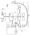
- the seal consists of a sealing tape 12, which is anchored in a housing (not shown here) and a monitoring device arranged in the same housing, here designated as a whole by 14.
- the monitoring device 14 comprises an opening sensor 16, a clock 18, a counter 20 ⁇ , a memory 22 and an operating voltage source 24.
- the opening sensor 16 includes a comparator 34, the signals coming from one input from the counter 20 ⁇ directly and the other input from the signals 20 ⁇ via a leading through the closed sealing tape 12 Signal path 36 are supplied.
- the memory 22 contains a plurality of memory locations, into which the current counter reading of the counter 20 ⁇ clocked by the clock generator 18 can be written in succession by means of a control logic 26 each time the opening sensor 16 responds.
- the stored data can be read out later via a data transmission device 28 which is connected to the memory 22.
- the memory 22 is designed as a non-volatile memory and has a rewritable area 30 ⁇ and a write-once area 32.
- rewritable area 30 ⁇ in addition to storage spaces for the current counter reading of the counter 20 ⁇ , storage spaces for logistic data are also provided.
- logistic data can e.g. B. the start time, the time zone, the place of destination, the destination, the country, the owner, the carrier or the means of transport.
- the write-once area 32 is for the storage of unchangeable characteristic data, such as. B. Factory number and first owner provided.
- Another output of the comparator 34 is connected to a switch 38 which, when the state of the Comparator 34 applied to the control logic 26 and the memory 22 operating voltage. During the other times when there are no write processes in the memory 22, the memory 22 and the control logic 26 are de-energized and in this way relieve the operating voltage source 24.
- a voltage monitoring circuit 44 ensures that when the operating voltage drops below a threshold value, a "low battery value" is written into one of the memory locations of the memory 22.
- the sealing tape 12 can be designed as an electrical conductor or as a light guide.
- a signal transmitter 40 36 and a signal receiver 42 also belong to the signal path 36, the part of which is the sealing wire 12.
- the sealing tape can be clamped at one end in a locking device 76 by means of an eccentric cam 78 and then comes into contact with an output terminal of the signal generator 40 ⁇ . If the sealing tape 12 is an electrical conductor, this can be a simple metallic contact. In the case of a light guide, a corresponding light source is required instead.
- a display device 46 is also connected, which as a simple indicator z. B. can be executed for a "seal open" signal or in the case of a numerical or alphanumeric display option also allows the display of the memory content.
- the data 22 in the memory can be called up from the outside by means of a data transmission device 28 and later evaluated centrally.
- the data transmission device 28 also enables a registration z. B. the logistic data in the memory 22.
- Part of the transmission device 28 is a unit 48 integrated in the housing, which produces a data transmission path with an external unit, not shown here.
- the circuit described so far works as follows. After the sealing tape 12 of the electronic seal has been passed through the eyelets of the lock of a container to be sealed, it is locked in the locking device 76 by means of the eccentric cam 78. The signal path 36 is thereby closed.
- the appropriate logistic data is written into the memory 22 and the seal is armed.
- the clock generator 18 now begins to switch the counter 20 ⁇ away from an initial value and the respective counter reading of the counter 20 ⁇ is evaluated by the comparator 34. As long as the signal path 36 is closed, in addition to the direct value of the counter 20 ⁇ , the comparator 34 also receives this value via the signal generator 40 ⁇ , the sealing tape 12 and the signal receiver 42. As long as the values at the two inputs of the comparator match, there is no change in the state at the exit. No data is therefore written into the memory 22.
- the comparator 34 recognizes this from the fact that different input values occur.
- a change in state at the output causes, via control logic 26, that the current state of counter 20 ⁇ is written into memory 22. This is a relative time specification, which, however, can later easily be converted into an absolute time specification due to the further logistic data in the memory 22.
- the switch 38 was activated, which applied the memory 22 and the control logic 26 to the operating voltage.
- a log can be created by reading out the stored data, which contains precise information about the time and duration of the opening of the electronic seal.
- the electronic seal can be used again and the previously saved data can be overwritten by others.
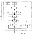
- a suitable data transmission device of the electronic seal is shown in the block diagram of FIG. 2.
- the data transmission device 28 comprises a unit 48 integrated in the housing of the electronic seal, as is also shown in FIG. 1, and an external unit 50 ⁇ .
- both transmitter and receiver are located in both units 48 and 50 ⁇ .
- the unit 48 is a transmitter 52 and a receiver 56 for data and commands. Accordingly, in the external unit 50 ⁇ a transmitter 54 and a receiver 58th
- the relevant transmitters 52 and 54 and receivers 56 and 58 of the two units 48 and 50 ⁇ are contactless and can be connected electromagnetically in the present case.
- an energy receiver 60 ⁇ with an energy store 62 is provided in the unit 48, which required the external unit 50 ⁇ via an energy transmitter 64 to read data from the memory or to write data into the memory 22 Relates to energy.
- a common resonance circuit 66 in the unit 48 or 68 in the unit 50 ⁇ is used for transmission, with which the relevant transmitter and receiver for data as well as the energy transmitter 64 on the side of the external unit 50 ⁇ and the energy receiver 60 ⁇ on the side of the unit 48 are connected .
- the energy receiver 60 ⁇ is followed by an energy store 62, which brings about a certain voltage stabilization and which in principle could also serve to charge the operating voltage source 24 in FIG. 1.
- the external unit 50 ⁇ comprises a further memory 70 ⁇ , a display device 72 and an input device 74. All the data transferred from the memory 22 to the further memory 70 ⁇ can now be displayed and evaluated on the display device 72. Furthermore, data to be entered can be prepared by means of the input device 74 and stored in the memory 70 ⁇ so that they are immediately available when a seal that has just been closed is activated. Due to the transmission device 28, a display device 46 in the housing of the electronic seal can largely be dispensed with, or the display can display a few values, such as, for. B. an opening indicator of the sealing wire can be limited. The stored data is then practically secret and can only be evaluated by people who have a corresponding external unit 50 ⁇ of the data transmission device 28.
- the data transmission between the units 48 and 50 ⁇ takes place when the resonance circuits 66 and 68 are sufficiently coupled together.
- 3 to 5 show different design options of the electronic seal.
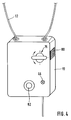
- the circuit of the electronic seal shown in Fig. 1 is located in a housing 10 ⁇ , which has openings for the sealing tape 12.
- the sealing tape can be fixed within the housing by means of the locking device 76. If the actuating lever of the locking device 76 is turned into a closed position, a catch 80 ⁇ engages, which prevents an inadvertent turning back into the open position. Only after pressing the catch 80 ⁇ can the locking device 76 be opened again.
- the electronic seal can easily be attached like a seal to the lock of a container in question. A separate attachment is therefore not necessary.
- an attachment hole 82 is provided for this purpose, through which a bolt can be inserted, which can then be inserted e.g. B. is screwed on the other side of the door of a container.
- the embodiment of the electronic seal shown in FIG. 3 has a display device 46, which is integrated in the housing 10 ⁇ .
- This display device 46 can display numerical and alphanumeric data about the memory content and also present a function and status display.
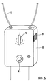
- FIGS. 4 and 5 a detailed display device is dispensed with. Rather, there is only one display device 46 z. B. provided in the form of a light-emitting diode, which only allows an indication of whether the seal was opened after arming or not.
- the fastening of the sealing tape 12 on the housing 10 ⁇ different designs are shown in FIGS. 4 and 5. 4, one end of the sealing tape 12 is firmly anchored in the housing and only the other end can be locked by means of the locking device 76.
- the advantage here is that the sealing tape 12 always remains connected to the housing 10 ⁇ , so that it cannot be lost.
- the sealing tape 12 can be fixed on both sides by means of the locking device 76 in the housing 10 ⁇ .
- This design has the advantage that the sealing tape 12 can be easily replaced in the event of damage.
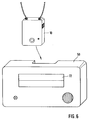
- FIG. 6 shows a view of an electronic seal in connection with an external unit.
- the external unit 50 ⁇ is here provided with a display device 72 which makes it possible to display the data stored in the memory 22 of the electronic seal.
- the arrow emanating from the housing 10 ⁇ of the electronic seal points to a groove within the housing of the external unit 50 ⁇ , into which the electronic seal can be inserted for better coupling of the resonant circuits.
- FIG. 7 shows the view of the housing of an electronic seal in connection with an external unit which has a remote input and output device.
- the housing with the slot into which the housing 10 ⁇ of the electronic seal is inserted for data transmission serves practically only as a read / write head.
- the storage, display, evaluation and input of data takes place via a remote computer, of which the display device 72 and the input device 74 are shown here.
- FIG. 8 also shows a longitudinal section through a locking device 76.
- This has a pivotable eccentric cam 78 which, in the locking position, presses the inserted sealing tape 12 against a contact spring 84 and, in the case of an electrical line, an electrical contact between the sealing tape 12 and the contact spring 84 manufactures.
- the eccentric cam 78 releases the insertion channel, as a result of which the sealing tape 12 can be pulled out of the slot.
Landscapes
- Engineering & Computer Science (AREA)
- Physics & Mathematics (AREA)
- General Physics & Mathematics (AREA)
- Computer Security & Cryptography (AREA)
- Theoretical Computer Science (AREA)
- Burglar Alarm Systems (AREA)
- Time Recorders, Dirve Recorders, Access Control (AREA)
- Packages (AREA)
- Closures For Containers (AREA)
- Sealing Using Fluids, Sealing Without Contact, And Removal Of Oil (AREA)
Applications Claiming Priority (2)
| Application Number | Priority Date | Filing Date | Title |
|---|---|---|---|
| DE4019265 | 1990-06-16 | ||
| DE4019265A DE4019265C1 (enExample) | 1990-06-16 | 1990-06-16 |
Publications (2)
| Publication Number | Publication Date |
|---|---|
| EP0463294A1 EP0463294A1 (de) | 1992-01-02 |
| EP0463294B1 true EP0463294B1 (de) | 1994-09-21 |
Family
ID=6408528
Family Applications (1)
| Application Number | Title | Priority Date | Filing Date |
|---|---|---|---|
| EP91104204A Expired - Lifetime EP0463294B1 (de) | 1990-06-16 | 1991-03-19 | Elektronisches Siegel |
Country Status (5)
| Country | Link |
|---|---|
| US (1) | US5189396A (enExample) |
| EP (1) | EP0463294B1 (enExample) |
| JP (1) | JP2981016B2 (enExample) |
| AT (1) | ATE112084T1 (enExample) |
| DE (2) | DE4019265C1 (enExample) |
Families Citing this family (99)
| Publication number | Priority date | Publication date | Assignee | Title |
|---|---|---|---|---|
| US5831531A (en) * | 1992-07-27 | 1998-11-03 | Micron Communications, Inc. | Anti-theft method for detecting the unauthorized opening of containers and baggage |
| US5406263A (en) * | 1992-07-27 | 1995-04-11 | Micron Communications, Inc. | Anti-theft method for detecting the unauthorized opening of containers and baggage |
| NL9300283A (nl) * | 1993-02-12 | 1994-09-01 | Kema Nv | Zegelsysteem voor een object, en een zegel daarvoor. |
| FR2701780B1 (fr) * | 1993-02-19 | 1997-08-29 | Claude Ricard | Dispositif d'inviolabilité pour capteur électronique de distance parcourue par un véhicule. |
| GB9306463D0 (en) * | 1993-03-29 | 1993-05-19 | Encrypta Electronics Ltd | Electronic seal |
| SE516639C2 (sv) * | 1993-03-30 | 2002-02-05 | Lennart Eriksson | Förfarande och anordning för försegling |
| US5515030A (en) * | 1993-04-09 | 1996-05-07 | Nynex Science & Technology, Inc. | Electronic seal |
| US7397363B2 (en) * | 1993-06-08 | 2008-07-08 | Raymond Anthony Joao | Control and/or monitoring apparatus and method |
| WO1995024022A1 (fr) * | 1994-03-01 | 1995-09-08 | Brand, Edith | Dispositif d'enregistrement electronique a partir d'un compteur a affichage lisible |
| WO1995024023A1 (fr) * | 1994-03-01 | 1995-09-08 | Brand, Edith | Dispositif de fixation ou de scellement electronique |
| EP0777890B1 (en) * | 1994-08-25 | 2005-01-19 | Geefield Pty. Ltd. | Method for providing identification |
| US5541577A (en) * | 1995-05-26 | 1996-07-30 | Consolidated Graphic Materials, Inc. | Electromagnetic asset protection system |
| US6069563A (en) * | 1996-03-05 | 2000-05-30 | Kadner; Steven P. | Seal system |
| US5656996A (en) * | 1996-03-13 | 1997-08-12 | Global Associates, Ltd. | Electronic security bonding device |
| US7277010B2 (en) * | 1996-03-27 | 2007-10-02 | Raymond Anthony Joao | Monitoring apparatus and method |
| US10152876B2 (en) | 1996-03-27 | 2018-12-11 | Gtj Ventures, Llc | Control, monitoring, and/or security apparatus and method |
| US7253731B2 (en) | 2001-01-23 | 2007-08-07 | Raymond Anthony Joao | Apparatus and method for providing shipment information |
| US10011247B2 (en) * | 1996-03-27 | 2018-07-03 | Gtj Ventures, Llc | Control, monitoring and/or security apparatus and method |
| EP0825554A1 (en) * | 1996-08-13 | 1998-02-25 | Fyrtech Microelectronics AB | Sealing device |
| AU5687798A (en) | 1996-12-03 | 1998-06-29 | E.J. Brooks Company | Programmable lock and security system therefor |
| US5912621A (en) * | 1997-07-14 | 1999-06-15 | Digital Equipment Corporation | Cabinet security state detection |
| US9075136B1 (en) | 1998-03-04 | 2015-07-07 | Gtj Ventures, Llc | Vehicle operator and/or occupant information apparatus and method |
| US5936523A (en) * | 1998-04-24 | 1999-08-10 | West; Joe F. | Device and method for detecting unwanted disposition of the contents of an enclosure |
| ES2138930B1 (es) * | 1998-05-05 | 2000-09-01 | Plaza Miranzo Jose | Precinto electronico. |
| ES2138931B1 (es) * | 1998-05-07 | 2000-10-16 | Plaza Miranzo Jose | Dispositivo electronico de precinto y deteccion de manipulacion de surtidores de carburantes. |
| DE69901298D1 (de) * | 1998-05-05 | 2002-05-23 | Miranzo Jose Plaza | Elektronisches siegel |
| DE19852527A1 (de) * | 1998-11-06 | 2000-05-11 | Bos Berlin Oberspree Sondermas | Siegel für ein verschließbares Gefäß oder Behältnis |
| US6265973B1 (en) | 1999-04-16 | 2001-07-24 | Transguard Industries, Inc. | Electronic security seal |
| WO2001075700A2 (en) * | 2000-04-04 | 2001-10-11 | Marconi Corporation Plc | Tracking and logistics management system and method |
| US6791465B2 (en) * | 2000-07-11 | 2004-09-14 | Sergei V. Blagin | Tamper indicating bolt |
| US6542114B1 (en) | 2000-09-07 | 2003-04-01 | Savi Technology, Inc. | Method and apparatus for tracking items using dual frequency tags |
| US6720888B2 (en) | 2000-09-07 | 2004-04-13 | Savi Technology, Inc. | Method and apparatus for tracking mobile devices using tags |
| US6765484B2 (en) | 2000-09-07 | 2004-07-20 | Savi Technology, Inc. | Method and apparatus for supplying commands to a tag |
| US6940392B2 (en) * | 2001-04-24 | 2005-09-06 | Savi Technology, Inc. | Method and apparatus for varying signals transmitted by a tag |
| FR2816434A1 (fr) * | 2000-11-06 | 2002-05-10 | Robert Stephan Touzet | Dispositif de scelle a puce electronique |
| EP1246094A1 (en) * | 2001-03-27 | 2002-10-02 | TELEFONAKTIEBOLAGET L M ERICSSON (publ) | Container surveillance system and related method |
| RU2178590C1 (ru) * | 2001-04-10 | 2002-01-20 | Закрытое акционерное общество "Трансэнерготехнология" | Гибкое запорно-пломбировочное устройство с электронной меткой (варианты) |
| US6747558B1 (en) | 2001-11-09 | 2004-06-08 | Savi Technology, Inc. | Method and apparatus for providing container security with a tag |
| US10562492B2 (en) * | 2002-05-01 | 2020-02-18 | Gtj Ventures, Llc | Control, monitoring and/or security apparatus and method |
| US7411495B2 (en) * | 2002-08-27 | 2008-08-12 | Hi-G-Tek Ltd. | Smart container monitoring system |
| US6753775B2 (en) * | 2002-08-27 | 2004-06-22 | Hi-G-Tek Ltd. | Smart container monitoring system |
| US6778083B2 (en) | 2002-08-27 | 2004-08-17 | Hi-G-Tek Ltd. | Electronic locking seal |
| US7002472B2 (en) * | 2002-09-04 | 2006-02-21 | Northrop Grumman Corporation | Smart and secure container |
| US20040100379A1 (en) * | 2002-09-17 | 2004-05-27 | Hans Boman | Method and system for monitoring containers to maintain the security thereof |
| US7479877B2 (en) * | 2002-09-17 | 2009-01-20 | Commerceguard Ab | Method and system for utilizing multiple sensors for monitoring container security, contents and condition |
| US7301462B1 (en) | 2002-09-19 | 2007-11-27 | Tc License, Ltd. | Tamper resistant electronic tag |
| US7042354B2 (en) * | 2002-12-11 | 2006-05-09 | Hi-G-Tek Ltd. | Tamper-resistant electronic seal |
| US20040215532A1 (en) * | 2003-02-25 | 2004-10-28 | Hans Boman | Method and system for monitoring relative movement of maritime containers and other cargo |
| US6995669B2 (en) * | 2003-03-25 | 2006-02-07 | Fernando Morales | System and method to enhance security of shipping containers |
| PL1473805T3 (pl) * | 2003-04-30 | 2011-11-30 | White Box Inc | Moduł złączy do termoelementów |
| US20050062606A1 (en) * | 2003-09-10 | 2005-03-24 | Ernst Konecnik | Arrangement and method for detecting unauthorized removal of electronic equipment |
| EP1692813B1 (en) * | 2003-10-06 | 2009-10-14 | International Business Machines Corporation | Documenting security related aspects in the process of container shipping |
| WO2005048206A1 (en) * | 2003-11-13 | 2005-05-26 | All Set Marine Security Ab | Method and system for monitoring containers to maintain the security thereof |
| US7135973B2 (en) * | 2004-02-13 | 2006-11-14 | Avery Dennison Corporation | Tamper monitoring article, system and method |
| JP4532144B2 (ja) * | 2004-03-19 | 2010-08-25 | 東芝テック株式会社 | 履歴管理システム |
| TWI374406B (en) * | 2004-03-24 | 2012-10-11 | All Set Marine Security Ab | Method and system for monitoring containers to maintain the security thereof |
| WO2005094172A2 (en) * | 2004-03-30 | 2005-10-13 | Hi-G-Tek Inc. | Monitorable locking assemblies |
| KR101230100B1 (ko) * | 2004-04-07 | 2013-02-05 | 코머스가드 에이비 | 컨테이너의 상태를 모니터링하는 방법 및 시스템 |
| US7198227B2 (en) * | 2004-06-10 | 2007-04-03 | Goodrich Corporation | Aircraft cargo locating system |
| WO2006048872A2 (en) * | 2004-11-02 | 2006-05-11 | Hi-G-Tek Inc. | Remotely monitorable electronic locking device |
| WO2006064523A1 (en) * | 2004-12-16 | 2006-06-22 | Gi.Bi.Effe S.R.L. | Tamper-proof box |
| US7212127B2 (en) * | 2004-12-20 | 2007-05-01 | Avery Dennison Corp. | RFID tag and label |
| DE102005001582A1 (de) | 2005-01-13 | 2006-07-27 | Robert Bosch Gmbh | Einrichtung und Verfahren zur Registrierung des Öffnens von Verschlüssen von zu sichernden Räumen |
| US7292149B2 (en) * | 2005-03-16 | 2007-11-06 | Elpas Electro-Optic Systems, Ltd. | Electronic monitoring device |
| WO2006116664A1 (en) * | 2005-04-26 | 2006-11-02 | Rf Code, Inc. | Tamper monitoring system and method |
| DE102005021914B4 (de) * | 2005-05-12 | 2011-01-05 | Hübner, Sebastian, Dr. | Omnidirektionaler Stoßsensor mit Indikatorfunktion |
| US7283052B2 (en) | 2005-05-13 | 2007-10-16 | Commerceguard Ab | Method and system for arming a multi-layered security system |
| US20070080802A1 (en) * | 2005-08-22 | 2007-04-12 | Cockburn John M | Tamper & intrusion detection device |
| GB0601977D0 (en) * | 2006-02-01 | 2006-03-15 | Alpha Asd Ltd | A high security lock & integral seal preventing unauthorised access to both passenger & military aircraft whilst unattended & waiting for next tour ofduty |
| EP1878861A1 (de) * | 2006-07-13 | 2008-01-16 | Siemens Aktiengesellschaft | Sicherungsvorrichtung für transportable Güter |
| DE102007017893A1 (de) * | 2007-04-13 | 2008-10-23 | Continental Automotive Gmbh | Detektionsvorrichtung |
| EP2083412A1 (de) * | 2008-01-25 | 2009-07-29 | SmTAG international AG | Überwachungseinrichtung |
| CN102307633A (zh) * | 2008-04-09 | 2012-01-04 | Igt公司 | 用于游戏桌的牌盒安全的系统和方法 |
| DE102008019964B4 (de) * | 2008-04-21 | 2013-02-28 | Deutsche Post Ag | Mobiler Frachtbehälter mit induktiver Energieversorgung; Umschlag- und/oder Transporteinrichtung für Frachtbehälter; Behälterlogistiksystem und Verfahren zur Energieversorgung eines Frachtbehälters |
| US8556167B1 (en) | 2008-06-16 | 2013-10-15 | Bank Of America Corporation | Prediction of future cash supply chain status |
| US9024722B2 (en) | 2008-06-16 | 2015-05-05 | Bank Of America Corporation | Remote identification equipped self-service monetary item handling device |
| US8094021B2 (en) | 2008-06-16 | 2012-01-10 | Bank Of America Corporation | Monetary package security during transport through cash supply chain |
| US8210429B1 (en) | 2008-10-31 | 2012-07-03 | Bank Of America Corporation | On demand transportation for cash handling device |
| US20100141445A1 (en) * | 2008-12-08 | 2010-06-10 | Savi Networks Inc. | Multi-Mode Commissioning/Decommissioning of Tags for Managing Assets |
| WO2011008871A1 (en) * | 2009-07-14 | 2011-01-20 | Savi Networks Llc | Security seal |
| US8456302B2 (en) | 2009-07-14 | 2013-06-04 | Savi Technology, Inc. | Wireless tracking and monitoring electronic seal |
| US8432274B2 (en) | 2009-07-31 | 2013-04-30 | Deal Magic, Inc. | Contextual based determination of accuracy of position fixes |
| KR20120099631A (ko) * | 2009-08-17 | 2012-09-11 | 사비 테크날러지 인코퍼레이티드 | 자산의 상황 인식 모니터링 |
| US20110050397A1 (en) * | 2009-08-28 | 2011-03-03 | Cova Nicholas D | System for generating supply chain management statistics from asset tracking data |
| US8334773B2 (en) * | 2009-08-28 | 2012-12-18 | Deal Magic, Inc. | Asset monitoring and tracking system |
| US8314704B2 (en) * | 2009-08-28 | 2012-11-20 | Deal Magic, Inc. | Asset tracking using alternative sources of position fix data |
| US20110054979A1 (en) * | 2009-08-31 | 2011-03-03 | Savi Networks Llc | Physical Event Management During Asset Tracking |
| US9019113B2 (en) * | 2009-10-13 | 2015-04-28 | Sennco Solutions, Inc. | Circuit, system and/or method for detecting an electrical connection between an electrical device and a power supply |
| CA2866877A1 (en) | 2012-03-09 | 2013-09-12 | Neology, Inc. | Tamper evident cargo container seal bolt lock |
| MX351492B (es) | 2012-03-19 | 2017-10-18 | Neology Inc | Seguro de perno sensible a la manipulacion para contenedor de carga. |
| WO2013158062A2 (en) | 2012-04-16 | 2013-10-24 | University Of Manitoba | Reusable electronic seal |
| US8982360B2 (en) * | 2013-02-27 | 2015-03-17 | Honeywell International Inc. | Apparatus and method of using a light conduit in a position detector |
| CN104103138A (zh) * | 2013-04-07 | 2014-10-15 | 北京中软冠群软件技术有限公司 | 基于位置服务剪断报警装置 |
| US10546441B2 (en) | 2013-06-04 | 2020-01-28 | Raymond Anthony Joao | Control, monitoring, and/or security, apparatus and method for premises, vehicles, and/or articles |
| US10217084B2 (en) | 2017-05-18 | 2019-02-26 | Bank Of America Corporation | System for processing resource deposits |
| US10515518B2 (en) | 2017-05-18 | 2019-12-24 | Bank Of America Corporation | System for providing on-demand resource delivery to resource dispensers |
| US10275972B2 (en) | 2017-05-18 | 2019-04-30 | Bank Of America Corporation | System for generating and providing sealed containers of traceable resources |
| DE102017118963A1 (de) * | 2017-08-18 | 2019-02-21 | Endress+Hauser Process Solutions Ag | Vorrichtung und Verfahren zum Detektieren von unbefugten Änderungen an einer Automatisierungskomponente |
| US12232281B2 (en) * | 2022-09-27 | 2025-02-18 | Xiamen Innov Information Science And Technology Co., Ltd. | Tamper-proofing electronic seal |
Family Cites Families (4)
| Publication number | Priority date | Publication date | Assignee | Title |
|---|---|---|---|---|
| US4234875A (en) * | 1978-03-06 | 1980-11-18 | Sandstone, Inc. | Security structure |
| US4262284A (en) * | 1978-06-26 | 1981-04-14 | Stieff Lorin R | Self-monitoring seal |
| AU575465B2 (en) * | 1985-02-05 | 1988-07-28 | Encrypta Electronics Limited | Apparatus for recording the opening or closing of a closure member |
| US4797663A (en) * | 1987-03-12 | 1989-01-10 | Tekmate Industries Inc. | Portable security monitor and time recording |
-
1990
- 1990-06-16 DE DE4019265A patent/DE4019265C1/de not_active Expired - Lifetime
-
1991
- 1991-03-19 AT AT91104204T patent/ATE112084T1/de active
- 1991-03-19 EP EP91104204A patent/EP0463294B1/de not_active Expired - Lifetime
- 1991-03-19 DE DE59103007T patent/DE59103007D1/de not_active Expired - Fee Related
- 1991-06-06 US US07/711,653 patent/US5189396A/en not_active Expired - Lifetime
- 1991-06-13 JP JP3142096A patent/JP2981016B2/ja not_active Expired - Fee Related
Also Published As
| Publication number | Publication date |
|---|---|
| JP2981016B2 (ja) | 1999-11-22 |
| EP0463294A1 (de) | 1992-01-02 |
| JPH04313194A (ja) | 1992-11-05 |
| DE59103007D1 (de) | 1994-10-27 |
| DE4019265C1 (enExample) | 1991-11-28 |
| US5189396A (en) | 1993-02-23 |
| ATE112084T1 (de) | 1994-10-15 |
Similar Documents
| Publication | Publication Date | Title |
|---|---|---|
| EP0463294B1 (de) | Elektronisches Siegel | |
| EP0401647B1 (de) | Schliessvorrichtung | |
| DE3040559C2 (enExample) | ||
| EP0183738B1 (de) | Kontrollanlage und verfahren zum ablesen und zur aufnahme der kenndaten von kontrollstellen bei einer überwachungsanlage | |
| DE3887341T2 (de) | Verriegelungssystem. | |
| EP1012430A1 (de) | Verfahren und vorrichtung zur schliesskontrolle von schlössern | |
| EP1089219A2 (de) | Verfahren zur Sicherung eines Datenspeichers | |
| EP0187363B1 (de) | Mechanisch und nichtmechanisch codierter Schlüssel sowie dadurch zu betätigendes Schloss | |
| DE102016112007A1 (de) | Schließanordnung, insbesondere Türschlossanordnung für einen Schaltschrank und ein entsprechendes Verfahren | |
| DE60105049T2 (de) | Intelligenter behälter | |
| DE202022105344U1 (de) | Plombiervorrichtung für Fahrzeugausstattungen | |
| DE3040571A1 (de) | Elektronische frankiermaschine mit datumspruefungs-warnanzeige | |
| DE102011108855A1 (de) | Elektronisches Siegel | |
| DE4334668C2 (de) | Verfahren zur sicheren Befüllung und Entleerung einer Gasflasche und Anordnung zur Durchführung des Verfahrens | |
| DE3040560A1 (de) | Frankiermaschine mit der faehigkeit zu einem interaktiven arithmetischen betrieb | |
| DE10357695A1 (de) | Wechselbehälter zur Aufbewahrung von Wertdokumenten | |
| DE2217139A1 (de) | Elektronische Schließanlage | |
| DE102007021138A1 (de) | Montageanordnung sowie Erfassungssystem mit einer solchen Anordnung | |
| DE3834538C1 (en) | Electronic control device on a control board for controlling a magnetic and/or electromechanical locking device for doors | |
| DE3409391A1 (de) | Magneto - elektronisches system zum oeffnen und schliessen von schloessern | |
| DE3040532C2 (de) | Nachladbare elektronische Frankiermaschine | |
| DE19809574A1 (de) | Verfahren zur Sicherung der Nämlichkeit von Objekten sowie Vorrichtung zur Durchführung des Verfahrens | |
| DE102012005142A1 (de) | Schließsystem für Türen von insbesondere Staufächern in einem Fahr- oder Flugzeug | |
| DE2923732A1 (de) | Alarmanlage | |
| DE102007052335A1 (de) | Verfahren zur Kontrolle bestehenden Feuerschutzes an Feuerschutztüren |
Legal Events
| Date | Code | Title | Description |
|---|---|---|---|
| PUAI | Public reference made under article 153(3) epc to a published international application that has entered the european phase |
Free format text: ORIGINAL CODE: 0009012 |
|
| AK | Designated contracting states |
Kind code of ref document: A1 Designated state(s): AT BE CH DE DK ES FR GB GR IT LI LU NL SE |
|
| 17P | Request for examination filed |
Effective date: 19920521 |
|
| 17Q | First examination report despatched |
Effective date: 19940317 |
|
| GRAA | (expected) grant |
Free format text: ORIGINAL CODE: 0009210 |
|
| AK | Designated contracting states |
Kind code of ref document: B1 Designated state(s): AT BE CH DE DK ES FR GB GR IT LI LU NL SE |
|
| PG25 | Lapsed in a contracting state [announced via postgrant information from national office to epo] |
Ref country code: ES Free format text: THE PATENT HAS BEEN ANNULLED BY A DECISION OF A NATIONAL AUTHORITY Effective date: 19940921 Ref country code: GR Free format text: LAPSE BECAUSE OF FAILURE TO SUBMIT A TRANSLATION OF THE DESCRIPTION OR TO PAY THE FEE WITHIN THE PRESCRIBED TIME-LIMIT Effective date: 19940921 Ref country code: BE Effective date: 19940921 |
|
| REF | Corresponds to: |
Ref document number: 112084 Country of ref document: AT Date of ref document: 19941015 Kind code of ref document: T |
|
| REF | Corresponds to: |
Ref document number: 59103007 Country of ref document: DE Date of ref document: 19941027 |
|
| ITF | It: translation for a ep patent filed | ||
| PG25 | Lapsed in a contracting state [announced via postgrant information from national office to epo] |
Ref country code: SE Effective date: 19941221 |
|
| ET | Fr: translation filed | ||
| GBT | Gb: translation of ep patent filed (gb section 77(6)(a)/1977) |
Effective date: 19950111 |
|
| PG25 | Lapsed in a contracting state [announced via postgrant information from national office to epo] |
Ref country code: DK Effective date: 19950319 Ref country code: AT Effective date: 19950319 |
|
| PG25 | Lapsed in a contracting state [announced via postgrant information from national office to epo] |
Ref country code: LU Free format text: LAPSE BECAUSE OF NON-PAYMENT OF DUE FEES Effective date: 19950331 |
|
| PLBE | No opposition filed within time limit |
Free format text: ORIGINAL CODE: 0009261 |
|
| STAA | Information on the status of an ep patent application or granted ep patent |
Free format text: STATUS: NO OPPOSITION FILED WITHIN TIME LIMIT |
|
| 26N | No opposition filed | ||
| PGFP | Annual fee paid to national office [announced via postgrant information from national office to epo] |
Ref country code: NL Payment date: 19990322 Year of fee payment: 9 |
|
| PGFP | Annual fee paid to national office [announced via postgrant information from national office to epo] |
Ref country code: CH Payment date: 19990324 Year of fee payment: 9 |
|
| PG25 | Lapsed in a contracting state [announced via postgrant information from national office to epo] |
Ref country code: LI Free format text: LAPSE BECAUSE OF NON-PAYMENT OF DUE FEES Effective date: 20000331 Ref country code: CH Free format text: LAPSE BECAUSE OF NON-PAYMENT OF DUE FEES Effective date: 20000331 |
|
| PG25 | Lapsed in a contracting state [announced via postgrant information from national office to epo] |
Ref country code: NL Free format text: LAPSE BECAUSE OF NON-PAYMENT OF DUE FEES Effective date: 20001001 |
|
| REG | Reference to a national code |
Ref country code: CH Ref legal event code: PL |
|
| NLV4 | Nl: lapsed or anulled due to non-payment of the annual fee |
Effective date: 20001001 |
|
| REG | Reference to a national code |
Ref country code: GB Ref legal event code: IF02 |
|
| PG25 | Lapsed in a contracting state [announced via postgrant information from national office to epo] |
Ref country code: IT Free format text: LAPSE BECAUSE OF NON-PAYMENT OF DUE FEES;WARNING: LAPSES OF ITALIAN PATENTS WITH EFFECTIVE DATE BEFORE 2007 MAY HAVE OCCURRED AT ANY TIME BEFORE 2007. THE CORRECT EFFECTIVE DATE MAY BE DIFFERENT FROM THE ONE RECORDED. Effective date: 20050319 |
|
| PGFP | Annual fee paid to national office [announced via postgrant information from national office to epo] |
Ref country code: DE Payment date: 20060316 Year of fee payment: 16 |
|
| PGFP | Annual fee paid to national office [announced via postgrant information from national office to epo] |
Ref country code: FR Payment date: 20060322 Year of fee payment: 16 |
|
| PGFP | Annual fee paid to national office [announced via postgrant information from national office to epo] |
Ref country code: GB Payment date: 20060323 Year of fee payment: 16 |
|
| GBPC | Gb: european patent ceased through non-payment of renewal fee |
Effective date: 20070319 |
|
| REG | Reference to a national code |
Ref country code: FR Ref legal event code: ST Effective date: 20071130 |
|
| PG25 | Lapsed in a contracting state [announced via postgrant information from national office to epo] |
Ref country code: DE Free format text: LAPSE BECAUSE OF NON-PAYMENT OF DUE FEES Effective date: 20071002 |
|
| PG25 | Lapsed in a contracting state [announced via postgrant information from national office to epo] |
Ref country code: GB Free format text: LAPSE BECAUSE OF NON-PAYMENT OF DUE FEES Effective date: 20070319 |
|
| PG25 | Lapsed in a contracting state [announced via postgrant information from national office to epo] |
Ref country code: FR Free format text: LAPSE BECAUSE OF NON-PAYMENT OF DUE FEES Effective date: 20070402 |