EP0462539B1 - Unité de surveillance d'un servomoteur - Google Patents
Unité de surveillance d'un servomoteur Download PDFInfo
- Publication number
- EP0462539B1 EP0462539B1 EP91109892A EP91109892A EP0462539B1 EP 0462539 B1 EP0462539 B1 EP 0462539B1 EP 91109892 A EP91109892 A EP 91109892A EP 91109892 A EP91109892 A EP 91109892A EP 0462539 B1 EP0462539 B1 EP 0462539B1
- Authority
- EP
- European Patent Office
- Prior art keywords
- servo motor
- fault
- servo
- difference
- feedback signal
- Prior art date
- Legal status (The legal status is an assumption and is not a legal conclusion. Google has not performed a legal analysis and makes no representation as to the accuracy of the status listed.)
- Expired - Lifetime
Links
Images


Classifications
-
- G—PHYSICS
- G05—CONTROLLING; REGULATING
- G05B—CONTROL OR REGULATING SYSTEMS IN GENERAL; FUNCTIONAL ELEMENTS OF SUCH SYSTEMS; MONITORING OR TESTING ARRANGEMENTS FOR SUCH SYSTEMS OR ELEMENTS
- G05B19/00—Programme-control systems
- G05B19/02—Programme-control systems electric
- G05B19/18—Numerical control [NC], i.e. automatically operating machines, in particular machine tools, e.g. in a manufacturing environment, so as to execute positioning, movement or co-ordinated operations by means of programme data in numerical form
- G05B19/406—Numerical control [NC], i.e. automatically operating machines, in particular machine tools, e.g. in a manufacturing environment, so as to execute positioning, movement or co-ordinated operations by means of programme data in numerical form characterised by monitoring or safety
- G05B19/4062—Monitoring servoloop, e.g. overload of servomotor, loss of feedback or reference
-
- G—PHYSICS
- G05—CONTROLLING; REGULATING
- G05B—CONTROL OR REGULATING SYSTEMS IN GENERAL; FUNCTIONAL ELEMENTS OF SUCH SYSTEMS; MONITORING OR TESTING ARRANGEMENTS FOR SUCH SYSTEMS OR ELEMENTS
- G05B2219/00—Program-control systems
- G05B2219/30—Nc systems
- G05B2219/34—Director, elements to supervisory
- G05B2219/34455—Different parameters are evaluated to indicate different faults
-
- G—PHYSICS
- G05—CONTROLLING; REGULATING
- G05B—CONTROL OR REGULATING SYSTEMS IN GENERAL; FUNCTIONAL ELEMENTS OF SUCH SYSTEMS; MONITORING OR TESTING ARRANGEMENTS FOR SUCH SYSTEMS OR ELEMENTS
- G05B2219/00—Program-control systems
- G05B2219/30—Nc systems
- G05B2219/37—Measurements
- G05B2219/37624—Detect collision, blocking by measuring change of velocity or torque
-
- G—PHYSICS
- G05—CONTROLLING; REGULATING
- G05B—CONTROL OR REGULATING SYSTEMS IN GENERAL; FUNCTIONAL ELEMENTS OF SUCH SYSTEMS; MONITORING OR TESTING ARRANGEMENTS FOR SUCH SYSTEMS OR ELEMENTS
- G05B2219/00—Program-control systems
- G05B2219/30—Nc systems
- G05B2219/42—Servomotor, servo controller kind till VSS
- G05B2219/42306—Excess in error, compare reference with feedback
-
- G—PHYSICS
- G05—CONTROLLING; REGULATING
- G05B—CONTROL OR REGULATING SYSTEMS IN GENERAL; FUNCTIONAL ELEMENTS OF SUCH SYSTEMS; MONITORING OR TESTING ARRANGEMENTS FOR SUCH SYSTEMS OR ELEMENTS
- G05B2219/00—Program-control systems
- G05B2219/30—Nc systems
- G05B2219/42—Servomotor, servo controller kind till VSS
- G05B2219/42321—Wrong direction or sign of measured value, eventually stop
Definitions
- This invention relates to a servo motor monitoring unit for monitoring a servo motor which drives a load, such as a machine tool, and more particularly to a servo motor monitoring unit with a fault detection and cause determination function.
- the PCT publication WO 88/05570 discloses a process and device for monitoring control elements such as safety devices in an automobile. Position command signals from a microprocessor as well as feedback position signals from the control element are fed to a common discrimination circuit. The received signals are continuously compared with set signals. When deviations are found, switching signals are generated and supplied to the microprocessor.
- the UK patent application GB-A-2 006 990 discloses a method and device for monitoring a controlled variable.
- the monitoring device comprises a logic unit which compares command signals with detected position and rotary speed signals of a motor.
- the device further comprises means for forming the first differential of the controlled variable, for example position or speed, with respect to time. Comparison means compare this differential value with predetermined command parameters and indicate a fault when a predetermined deviation is present.
- a troubleshooting unit is also known for use with a motor controller (see Japanese Patent Disclosure Publication No. 291682 of 1989) which comprises a plurality of status observers for selectively monitoring control signals, e.g. voltage, current, speed and other signals, and estimating the disturbance torque of a motor in different modes. A fault location is guesstimated from the estimated values. Since such unit employs a plurality of status observers, the constants of the motor must be exactly known. In general, however, the motor constants are easily affected by individual differences and temperature, leading to errors. In addition, what is essential in controlling a servo motor is whether the actual position is tracking the position commands.
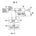
- a servo motor monitoring unit 601 comprises a counting section 601a for receiving a position command signal P R and a position detection feedback signal P F and operating on a difference therebetween, and a range determining section 601b for determining fault if the difference obtained by the counting section 601a is greater than a predetermined threshold value, and outputting a fault alarm such as "excessive error.”
- numeral 602 indicates a servo motor, 603 a position detector for detecting the position of the servo motor 602, 604 a position command generator for outputting the position command signal, and 605 a servo controller for controlling the driving of the servo motor 602 in accordance with the position command signal P R and the position detection feedback signal P F .
- the servo controller 605 compares the position command signal P R output by the position command generator 604 and the position detector 603 and controls the drive current of the servo motor 602.
- the position detector 603 outputs the position detection feedback signal P F in accordance with the operation of the servo motor 602. In the servo motor control system as described above, the position detection feedback signal P F cannot track the position command signal P R when: (1) the load is too heavy to generate acceleration; (2) the polarity of the position detection feedback signal P F from the position detector 603 is reversed; and (3) electrical connections to the servo motor 602 are improper.
- the servo motor monitoring unit 601 causes the counting section 601a to operate on the difference between the position command signal P R and the position detection feedback signal P F , and causes the range determining section 601B to compare that difference with a predetermined threshold value, determine that a fault has occurred if the difference is larger than the threshold value, and output a fault alarm.
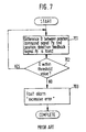
- Fig. 7 is a flowchart illustrating the sequence of said operation.
- the difference D between the position command signal P R and the position detection feedback signal P F is found (step 701).
- whether the difference D is within the range of the predetermined threshold value is determined (step 702).
- the fault alarm "excessive error” is output if the difference D is outside the threshold value range (step 703).
- the operation returns to step 701 and repeats processing.
- the known servo motor monitoring unit may be able to determine the occurrence of a fault in accordance with the difference D between the position command signal P R and the position detection feedback signal P F , but cannot determine the cause thereof. It cannot determine whether the difference D has increased due to insufficient torque because the machine (load) is too heavy or has collided with an obstacle, or due to opposite servo because of incorrect connection to the servo motor, or because the feedback of the equipment has been connected reversely. Hence, when the fault alarm "excessive error" is output, the cause of the fault must be investigated, taking much time.
- an object of the present invention to overcome the disadvantages in the prior art by providing a servo motor monitoring unit which allows the servo motor controller to be easily restored in a short time when the difference D between the position command signal P R and the position detection feedback signal P F is determined to be excessive.
- a servo motor monitoring device is provided as defined in claim 1.
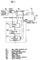
- Fig. 1 illustrates the configuration of a servo system to which the servo motor monitoring unit 101 has been applied.
- the servo motor monitoring unit 101 comprises a counting section 101a for receiving a position command signal P R and a position detection feedback signal P F and determining the difference D therebetween, a range determining section 101b for determining fault if the difference D obtained by the counting section 101a is greater than a predetermined threshold value, and a determining section 101c for determining the cause of fault occurrence in accordance with a sign of the position detection feedback signal P F (i.e., the sign of the acceleration of this signal) and that of a current feedback value P 0 .
- a sign of the position detection feedback signal P F i.e., the sign of the acceleration of this signal
- 1, numeral 102 indicates a servo motor; 103, a position detector for detecting the position of the servo motor 102; 104, a position command generator for outputting position command signals, and 105, a servo controller for controlling the power delivered to the servo motor 102 in accordance with the position command signal P R and the position detection feedback signal P F .
- the servo controller 105 compares the position command signal P R output by the position command generator 104 and the position detection feedback signal P F output by the position detector 103 to control the current used in driving the servo motor 102. As the servo motor 102 runs, the position detector 103 outputs the position detection feedback signal P F accordingly. In the meantime, the servo motor monitoring unit 101 causes the counting section 101a to determine the difference between the position command signal P R and the position detection feedback signal P F , cause the range determining section 101B to compare that difference with a predetermined threshold value and determine the occurrence of fault if the difference is larger than the threshold value.
- the determining section 101c compares the sign b of the acceleration of the position detection feedback signal P F and that of the current feedback value P 0 , and determines the cause of the excessive position error as "insufficient torque” if the signs match, or "opposite servo" if the signs do not match.
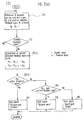
- Fig. 2 is a flowchart illustrating the sequence of the above operation.
- the difference D between the position command signal P R and the position detection feedback signal P F is found (step 201). Then, whether the difference D is within a given range of a predetermined threshold value (determination value) or not is determined (step 202), and the sign b of the acceleration of the position detection feedback signal P F is compared with the current feedback sign (sign of the current feedback value P 0 ) if the difference D is outside the threshold value range (step 203). If the above signs do not match, an "opposite servo" fault alarm is output (step 204), or if they match, an "insufficient torque” fault alarm is output (step 205). On the other hand, if the difference D is within the threshold value range, the operation returns to step 201 and repeats processing.
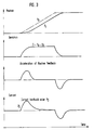
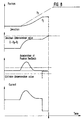
- Fig. 3 illustrates the waveforms of the output signals (position command signal P R , position detection feedback signal P F and current feedback value P 0 ) provided by the corresponding portions of the servo control system when operating without fault, and also shows the acceleration of the position feedback signal. Note that the above embodiment assumes that a positive current flows when the servo motor accelerates in the forward direction.
- the top graph in Fig. 3 gives the relationship between the position command signal P R and position detection feedback signal P F , the next graph indicates the difference therebetween, and the bottom graph indicates the change in the current feedback value P 0 .
- Fig. 4 provides an example of "insufficient torque,” wherein acceleration is initiated at t 0 , but due to a current limitation at t 1 , the position detection feedback signal P F cannot track the position command signal P R normally, and the difference D therebetween exceeds the threshold value at t A , resulting in a fault alarm. Since the sign of the position detection feedback signal (i.e., the sign of the acceleration of this signal) matches that of the current feedback value P 0 in this case, the cause of the fault can be determined as "insufficient torque".
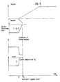
- Fig. 5 indicates an example of "opposite servo," wherein the position command signal P R has been output at t 0 , but the motor runs abnormally in a direction opposite to the command of the position command signal P R due to positive feedback caused by opposite servo, and the difference D exceeds the threshold value, resulting in a fault alarm. Since the sign of the position detection feedback signal (i.e., the sign of the acceleration of this signal) does not match that of the current feedback value P 0 in this case, the cause of the fault can be determined as "opposite servo". In the above embodiment, it has been assumed that positive current feedback (i.e. the current feedback value P 0 is positive) flows when the motor is accelerated in the forward direction. When the opposite assumption is made, it will be appreciated that the cause of the fault will be determined as "opposite servo" if the position detection feedback signal sign a matches the current feedback value P 0 sign, and as "insufficient torque” if they do not match.
- the sign of the position detection feedback signal i.
- inability to accelerate the servo motor due to a heavy machine load is not differentiated from collision of the machine with an obstacle and both are determined as "insufficient torque.”
- FIG. 2(a) A flowchart showing the operation of this alternative is shown in Fig. 2(a), and a timing chart is depicted in Fig. 8.
- the possibility of collision is checked by calculating the acceleration value within the difference detection routine (see step 202(a)), and branching at step 202(b) if the acceleration falls below a given threshold. In this instance, machine collision is discriminated and a "machine collision" fault alarm is raised.
- the flowchart of Fig. 2(a) is otherwise the same as that of Fig. 2. That, is, if the acceleration has not dropped, comparison of the acceleration sign with that of the current feedback is carried out at step 203.
- determining section 101c performs the additional function of acceleration value threshold comparison.
- a servo motor monitoring unit includes fault determining means for determining a fault in servo motor operating status and the cause of the fault in accordance with a position command signal, a position detection feedback signal and the feedback value of motor current supplied to said servo motor.
- the monitoring unit therefore allows the servo motor controller to be easily restored within a short period when the difference D between the position command signal P R and position detection feedback signal P F becomes excessive.
- the servo motor monitoring unit provides quick troubleshooting at occurrence of any fault, ensuring improved maintenance performance.
Landscapes
- Engineering & Computer Science (AREA)
- Human Computer Interaction (AREA)
- Manufacturing & Machinery (AREA)
- Physics & Mathematics (AREA)
- General Physics & Mathematics (AREA)
- Automation & Control Theory (AREA)
- Control Of Electric Motors In General (AREA)
Claims (2)
- Dispositif de contrôle de servomoteur comprenant :un détecteur de position (103) pour contrôler une position du servo moteur (102) et pour produire un signal de rétroaction de détection de position (Pf) ;un moyen de détection (101a) pour détecter une différence entre un signal de commande de position (Pr) fourni par un générateur de commande de position (104) à un servo contrôleur (105) pour ledit servomoteur (102) et ledit signal de rétroaction de détection de position (Pf) ; etun moyen de détermination de gamme (101b) pour comparer ladite différence à une gamme prédéterminée de valeurs de différence acceptables (D) et, lorsque ladite différence est hors de ladite gamme, produire un signal de défaut représentatif d'un défaut ; etcaractérisé parun moyen de détermination de signe (101c) répondant audit signal de défaut pour comparer le signe (b) de la dérivée seconde (accélération) du signal de rétroaction de détection de position (Pf) au signe du courant (Po) appliqué au servomoteur (102), ledit courant (Po) étant fourni au moyen de détermination de signe (101c) en une valeur de référence de courant du servocontrôleur (105), oùledit moyen de détermination de signe (101c) est adapté pour effectuer une discrimination du défaut sur la base de la comparaison des signes en produisant une première alarme de défaut indiquant une condition de forte charge ("couple insuffisant") si les signes concordent et en produisant une seconde alarme de défaut indiquant une condition d'asservissement inverse ("asservissement opposé") si les signes ne concordent pas.
- Dispositif de la revendication 1, dans lequel le servo moteur précité (102) est utilisé pour commander la position d'au moins un élément déplaçable d'une machine et où le moyen de détermination précité (101c) comprend un moyen pour effectuer une discrimination entre une condition de forte charge ("couple insuffisant") et une condition de collision de machine en détectant une chute soudaine dans la dérivée seconde (accélération) du signal de rétroaction de détection de position précité (Pf).
Applications Claiming Priority (2)
| Application Number | Priority Date | Filing Date | Title |
|---|---|---|---|
| JP161097/90 | 1990-06-19 | ||
| JP2161097A JPH0454885A (ja) | 1990-06-19 | 1990-06-19 | サーボモータ用監視装置 |
Publications (2)
| Publication Number | Publication Date |
|---|---|
| EP0462539A1 EP0462539A1 (fr) | 1991-12-27 |
| EP0462539B1 true EP0462539B1 (fr) | 1997-03-05 |
Family
ID=15728549
Family Applications (1)
| Application Number | Title | Priority Date | Filing Date |
|---|---|---|---|
| EP91109892A Expired - Lifetime EP0462539B1 (fr) | 1990-06-19 | 1991-06-17 | Unité de surveillance d'un servomoteur |
Country Status (4)
| Country | Link |
|---|---|
| US (1) | US5210476A (fr) |
| EP (1) | EP0462539B1 (fr) |
| JP (1) | JPH0454885A (fr) |
| DE (1) | DE69124848T2 (fr) |
Cited By (1)
| Publication number | Priority date | Publication date | Assignee | Title |
|---|---|---|---|---|
| DE19960834B4 (de) * | 1999-12-16 | 2006-10-26 | Agie S.A., Losone | Verfahren und Vorrichtung zur Störungserfassung, insbesondere zur Kollisionserfassung, im Antriebssystem einer numerisch gesteuerten Werkzeugmaschine |
Families Citing this family (29)
| Publication number | Priority date | Publication date | Assignee | Title |
|---|---|---|---|---|
| EP0578062A3 (fr) * | 1992-06-29 | 1995-05-10 | Sunny Co Ltd | Système de commande pour entraîner un objet. |
| KR0168068B1 (ko) * | 1992-10-19 | 1999-03-20 | 윤종용 | 위치제어시스템의 위치정보 판별장치 및 그 판별방법 |
| JP2819367B2 (ja) * | 1992-12-18 | 1998-10-30 | 日東工器株式会社 | マニピュレータの安全操作システム |
| US5325028A (en) * | 1993-03-26 | 1994-06-28 | Storage Technology Corporation | System and method for magnetic tape leader block extraction |
| US5548195A (en) * | 1994-12-22 | 1996-08-20 | International Business Machines Corporation | Compensated servo control stage positioning apparatus |
| JP3091388B2 (ja) * | 1995-04-19 | 2000-09-25 | ファナック株式会社 | モータの暴走検出方法および暴走検出装置 |
| EP0791872A1 (fr) * | 1996-02-27 | 1997-08-27 | Siemens Aktiengesellschaft | Dispositif et méthode de surveillance des embrayages et/ou transmission à courroie dans les axes ou arbres des machine-outils, robots |
| DE29621617U1 (de) * | 1996-12-12 | 1997-03-13 | Siemens Ag | Vorrichtung zur Überwachung und Begrenzung der statischen Schließkraft einer längsgeführt hin und her bewegbaren Masse |
| DE19746065A1 (de) * | 1997-10-17 | 1999-04-22 | Heidenhain Gmbh Dr Johannes | Verfahren und Schaltungsanordnung zur Überwachung der Regelbarkeit von Elektromotoren |
| EP1246035A1 (fr) * | 2001-03-28 | 2002-10-02 | Techspace Aero S.A. | Procédé et dispositif de commande d'un moteur électrique |
| US6598859B1 (en) | 2001-05-31 | 2003-07-29 | Magnetek, Inc. | Multiple hoist synchronization apparatus and method |
| US6731085B2 (en) * | 2002-04-02 | 2004-05-04 | Trw Inc. | Method and apparatus for determining motor faults in an electric assist steering system |
| FR2848358B1 (fr) * | 2002-12-04 | 2005-03-18 | Roulements Soc Nouvelle | Systeme d'actionnement comprenant un capteur numerique de position |
| US7408317B2 (en) * | 2005-05-04 | 2008-08-05 | Wildeck, Inc. | Apparatus having a motor, controller for the motor, and method of controlling the motor |
| US20070033785A1 (en) * | 2005-08-09 | 2007-02-15 | Kohring Mark D | Ridge vent with biocidal source |
| US7392790B2 (en) * | 2006-01-20 | 2008-07-01 | Caterpillar Inc. | System and method for resolving crossed electrical leads |
| US7370635B2 (en) * | 2006-01-20 | 2008-05-13 | Caterpillar Inc. | System and method for resolving electrical leads |
| JP4241785B2 (ja) * | 2006-08-31 | 2009-03-18 | 株式会社東芝 | サーボ制御装置 |
| JP2008259280A (ja) * | 2007-04-03 | 2008-10-23 | Hitachi Ltd | モータコントローラの診断方法 |
| JP4868022B2 (ja) * | 2009-04-27 | 2012-02-01 | トヨタ自動車株式会社 | モータ制御システムの異常判定装置 |
| JP5367623B2 (ja) * | 2010-03-15 | 2013-12-11 | オムロン株式会社 | サーボシステム、サーボモータ駆動装置、セーフティユニットおよびサーボシステムの制御方法 |
| WO2012063352A1 (fr) | 2010-11-11 | 2012-05-18 | 三菱電機株式会社 | Système de commande de moteur et procédé de surveillance de sécurité associé |
| JP2014235587A (ja) * | 2013-06-03 | 2014-12-15 | 東芝機械株式会社 | 工作機械およびその制御方法 |
| MX2016009933A (es) * | 2014-02-07 | 2017-01-23 | Nidec Motor Corp | Sistemas, dispositivos, y metodos para monitoreo de motor. |
| KR102493907B1 (ko) | 2015-06-25 | 2023-01-31 | 엘지이노텍 주식회사 | 액츄에이터 및 그 제어방법 |
| JP6346206B2 (ja) * | 2016-01-14 | 2018-06-20 | ファナック株式会社 | ブロック時間表示手段を有する数値制御装置 |
| US10603234B2 (en) * | 2016-03-30 | 2020-03-31 | Stryker Corporation | Patient support apparatuses with drive systems |
| JP6620380B1 (ja) * | 2019-02-12 | 2019-12-18 | 株式会社安川電機 | モータ制御システム |
| US11890234B2 (en) * | 2019-12-30 | 2024-02-06 | Stryker Corporation | Patient transport apparatus with crash detection |
Family Cites Families (9)
| Publication number | Priority date | Publication date | Assignee | Title |
|---|---|---|---|---|
| DE2744984A1 (de) * | 1977-10-06 | 1979-04-12 | Schoppe & Faeser Gmbh | Verfahren und einrichtung zur ueberwachung eines stellantriebes auf stoerungen |
| JPS57113118A (en) * | 1980-12-30 | 1982-07-14 | Fanuc Ltd | Robot control system |
| DE3135886A1 (de) * | 1981-09-10 | 1983-03-24 | Robert Bosch Gmbh, 7000 Stuttgart | Einrichtung zur positierung wenigstens einer verstellvorrichtung, insbesondere fuer kraftfahrzeugsitze |
| JPS5890204A (ja) * | 1981-11-25 | 1983-05-28 | Fanuc Ltd | 位置制御装置におけるフォローアップ回路 |
| FR2520523A1 (fr) * | 1982-01-27 | 1983-07-29 | Commissariat Energie Atomique | Structure de commande analogique pour boucles d'asservissement de la position en rotation d'un moteur a charge inertielle variable |
| FR2548399A1 (fr) * | 1983-07-01 | 1985-01-04 | Quenderff Jean Philippe | Dispositif electronique d'asservissement numerique par comparaison de frequences en temps reel |
| DE3701714A1 (de) * | 1987-01-22 | 1988-08-04 | Bosch Gmbh Robert | Verfahren und vorrichtung zur ueberwachung rechnergesteuerter stellglieder |
| DE3741973A1 (de) * | 1987-12-11 | 1989-06-22 | Voith Gmbh J M | Verfahren zum ueberwachen des arbeitsablaufes einer werkzeugmaschine |
| JPH02178811A (ja) * | 1988-12-29 | 1990-07-11 | Hitachi Seiko Ltd | サーボ制御装置 |
-
1990
- 1990-06-19 JP JP2161097A patent/JPH0454885A/ja active Pending
-
1991
- 1991-06-17 EP EP91109892A patent/EP0462539B1/fr not_active Expired - Lifetime
- 1991-06-17 DE DE69124848T patent/DE69124848T2/de not_active Expired - Fee Related
- 1991-06-18 US US07/717,143 patent/US5210476A/en not_active Expired - Lifetime
Cited By (1)
| Publication number | Priority date | Publication date | Assignee | Title |
|---|---|---|---|---|
| DE19960834B4 (de) * | 1999-12-16 | 2006-10-26 | Agie S.A., Losone | Verfahren und Vorrichtung zur Störungserfassung, insbesondere zur Kollisionserfassung, im Antriebssystem einer numerisch gesteuerten Werkzeugmaschine |
Also Published As
| Publication number | Publication date |
|---|---|
| JPH0454885A (ja) | 1992-02-21 |
| EP0462539A1 (fr) | 1991-12-27 |
| US5210476A (en) | 1993-05-11 |
| DE69124848T2 (de) | 1997-10-09 |
| DE69124848D1 (de) | 1997-04-10 |
Similar Documents
| Publication | Publication Date | Title |
|---|---|---|
| EP0462539B1 (fr) | Unité de surveillance d'un servomoteur | |
| KR100275237B1 (ko) | 부하 단락 고장의 검출방법 및 그 장치 | |
| US5677611A (en) | Control apparatus for an electric vehicle | |
| KR970002525A (ko) | 서보제어시스템의 이상검출ㆍ진단방법 및 자동적정화방법 | |
| JPS5826525A (ja) | 判別回路 | |
| US5720361A (en) | Torque sensing power steering device with abnormality detection, dead zone detection and power assist motor inhibition | |
| EP0770027B1 (fr) | Detecteur de surcharge destine a des machines a servomoteurs | |
| EP1622250B1 (fr) | Dispositif de commande d'un moteur électrique | |
| JPH02501960A (ja) | 計算機により制御される操作素子の監視方法及び回路装置 | |
| JPH07111703A (ja) | 車両の安全装置 | |
| KR960012683B1 (ko) | 엘리베이터의 종단계 감속 장치 | |
| EP3499327B1 (fr) | Dispositif de diagnostic d'état de charge et procédé de diagnostic d'état de charge pour servomoteur | |
| EP0838244A1 (fr) | Circuits de contrÔle pour appareils d'exercices physiques | |
| JP4116099B2 (ja) | 駆動部用の安全装置 | |
| EP0887628B1 (fr) | Système de sécurité | |
| KR20170091351A (ko) | 조향모터제어장치 및 방법 | |
| KR101801299B1 (ko) | 전동기의 고장 진단에 따른 고장 진단 정보를 이용한 전동기용 구동제어장치 | |
| JP3316238B2 (ja) | 静電塗装装置の電流異常検出装置 | |
| KR100365921B1 (ko) | 서보모터제어장치 및 제어방법 | |
| GB2282250A (en) | Processor watchdog circuit. | |
| KR200291555Y1 (ko) | 사상압연기의 정상통판 감시장치 | |
| KR20210074013A (ko) | 과전류 감지 회로 및 그 방법 | |
| US6583594B2 (en) | Electric power steering apparatus | |
| JPH05319722A (ja) | エレベータの速度制御装置 | |
| KR20230105270A (ko) | 모터 구동 장치 및 모터 구동 방법 |
Legal Events
| Date | Code | Title | Description |
|---|---|---|---|
| PUAI | Public reference made under article 153(3) epc to a published international application that has entered the european phase |
Free format text: ORIGINAL CODE: 0009012 |
|
| AK | Designated contracting states |
Kind code of ref document: A1 Designated state(s): DE GB |
|
| 17P | Request for examination filed |
Effective date: 19920430 |
|
| 17Q | First examination report despatched |
Effective date: 19940310 |
|
| GRAG | Despatch of communication of intention to grant |
Free format text: ORIGINAL CODE: EPIDOS AGRA |
|
| GRAH | Despatch of communication of intention to grant a patent |
Free format text: ORIGINAL CODE: EPIDOS IGRA |
|
| GRAH | Despatch of communication of intention to grant a patent |
Free format text: ORIGINAL CODE: EPIDOS IGRA |
|
| GRAA | (expected) grant |
Free format text: ORIGINAL CODE: 0009210 |
|
| AK | Designated contracting states |
Kind code of ref document: B1 Designated state(s): DE GB |
|
| REF | Corresponds to: |
Ref document number: 69124848 Country of ref document: DE Date of ref document: 19970410 |
|
| REG | Reference to a national code |
Ref country code: GB Ref legal event code: 727 |
|
| REG | Reference to a national code |
Ref country code: GB Ref legal event code: 727A |
|
| PLBE | No opposition filed within time limit |
Free format text: ORIGINAL CODE: 0009261 |
|
| STAA | Information on the status of an ep patent application or granted ep patent |
Free format text: STATUS: NO OPPOSITION FILED WITHIN TIME LIMIT |
|
| 26N | No opposition filed | ||
| REG | Reference to a national code |
Ref country code: GB Ref legal event code: 727B |
|
| REG | Reference to a national code |
Ref country code: GB Ref legal event code: SP |
|
| PGFP | Annual fee paid to national office [announced via postgrant information from national office to epo] |
Ref country code: GB Payment date: 19980608 Year of fee payment: 8 |
|
| PG25 | Lapsed in a contracting state [announced via postgrant information from national office to epo] |
Ref country code: GB Free format text: LAPSE BECAUSE OF NON-PAYMENT OF DUE FEES Effective date: 19990617 |
|
| GBPC | Gb: european patent ceased through non-payment of renewal fee |
Effective date: 19990617 |
|
| PGFP | Annual fee paid to national office [announced via postgrant information from national office to epo] |
Ref country code: DE Payment date: 20090615 Year of fee payment: 19 |
|
| PG25 | Lapsed in a contracting state [announced via postgrant information from national office to epo] |
Ref country code: DE Free format text: LAPSE BECAUSE OF NON-PAYMENT OF DUE FEES Effective date: 20110101 |