EP0462046B1 - Installation hydraulique sur le dispositif de fermeture pour presse à injection de matières plastiques - Google Patents
Installation hydraulique sur le dispositif de fermeture pour presse à injection de matières plastiques Download PDFInfo
- Publication number
- EP0462046B1 EP0462046B1 EP91710013A EP91710013A EP0462046B1 EP 0462046 B1 EP0462046 B1 EP 0462046B1 EP 91710013 A EP91710013 A EP 91710013A EP 91710013 A EP91710013 A EP 91710013A EP 0462046 B1 EP0462046 B1 EP 0462046B1
- Authority
- EP
- European Patent Office
- Prior art keywords
- pressure
- cylinder
- piston
- valve
- chamber
- Prior art date
- Legal status (The legal status is an assumption and is not a legal conclusion. Google has not performed a legal analysis and makes no representation as to the accuracy of the status listed.)
- Expired - Lifetime
Links
Images

Classifications
-
- B—PERFORMING OPERATIONS; TRANSPORTING
- B29—WORKING OF PLASTICS; WORKING OF SUBSTANCES IN A PLASTIC STATE IN GENERAL
- B29C—SHAPING OR JOINING OF PLASTICS; SHAPING OF MATERIAL IN A PLASTIC STATE, NOT OTHERWISE PROVIDED FOR; AFTER-TREATMENT OF THE SHAPED PRODUCTS, e.g. REPAIRING
- B29C45/00—Injection moulding, i.e. forcing the required volume of moulding material through a nozzle into a closed mould; Apparatus therefor
- B29C45/17—Component parts, details or accessories; Auxiliary operations
- B29C45/64—Mould opening, closing or clamping devices
- B29C45/67—Mould opening, closing or clamping devices hydraulic
- B29C45/6764—Mould opening, closing or clamping devices hydraulic using hydraulically connectable chambers of the clamping cylinder during the mould opening and closing movement
- B29C45/6771—Mould opening, closing or clamping devices hydraulic using hydraulically connectable chambers of the clamping cylinder during the mould opening and closing movement the connection being provided within the clamping cylinder
-
- B—PERFORMING OPERATIONS; TRANSPORTING
- B29—WORKING OF PLASTICS; WORKING OF SUBSTANCES IN A PLASTIC STATE IN GENERAL
- B29C—SHAPING OR JOINING OF PLASTICS; SHAPING OF MATERIAL IN A PLASTIC STATE, NOT OTHERWISE PROVIDED FOR; AFTER-TREATMENT OF THE SHAPED PRODUCTS, e.g. REPAIRING
- B29C45/00—Injection moulding, i.e. forcing the required volume of moulding material through a nozzle into a closed mould; Apparatus therefor
- B29C45/17—Component parts, details or accessories; Auxiliary operations
- B29C45/64—Mould opening, closing or clamping devices
- B29C45/67—Mould opening, closing or clamping devices hydraulic
- B29C2045/6785—Mould opening, closing or clamping devices hydraulic interconnecting two cylinders to supply fluid from one cylinder to the other during movement of the pistons
Definitions
- the invention relates to a hydraulic device according to the preamble of claim 1.
- the injection mold is closed in that the cylinder chamber of the drive cylinder on the mold side is supplied with pressure medium via the control valve in the case of a superimposed pressure control by means of a pressure sensor.
- the pressure medium displaced from the rear cylinder space of the drive cylinder during the closing movement reaches the tank via a line provided with a pressure sensor for an overlying pressure control and via the control valve.
- the invention has for its object to develop a hydraulic device of the type mentioned in such a way that the performance of the plastic injection molding machine can be increased significantly with gentle speed and pressure profiles of the mold carrier movement.
- the closing movements are accelerated when the mold closing unit is closed.
- the speed profiles and pressure profiles required for this can be adapted to a greater extent to the respective mechanical engineering and injection molding requirements.
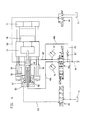
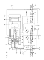
- the closing movement begins with simultaneous influence on both sides of the stationary differential piston of the drive cylinder with one-sided piston action and, as a result, higher acceleration force as required up to a certain desired speed (transition circuit according to FIG. 3). If the 4/4-way valve is switched through further, there is a continuous transition from direct piston action (transition switching position according to FIG. 3) to the differential switching (FIG. 4).
- the differential switch position is generally the same as in the gradual transition from the initial transition switch position (FIG. 3) to the differential circuit (FIG. 4) with an approximately stepless cross-sectional change in the flow openings in the 4/4-way valve transferred to the transition switching position (Fig. 3).
- the prerequisites may also exist for the final phase of the closing movement (transition switch position according to FIG. 3) to be continuously transferred to an outlet movement regulated by a pressure sensor (limit switch according to FIG. 5) in which the high-pressure chamber of the pressure cylinder is already open 'Locking pressure' is controlled so that the injection mold closes almost vibration-free when it runs smoothly.
- the prerequisites are met for the injection mold to be pressure-controlled with great force (tear-open movement according to FIG. 6) and to be opened with adaptation to the respective requirements.
- the hydraulic device can be used regardless of the number of its pressure cylinders or compensating cylinders and their arrangement.
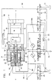
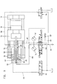
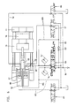
- Figures 1, 2 show the basic circuit diagram of mold clamping units, which differ in the number of their pressure or compensating cylinders and their arrangement.
- FIGs. 3 to 6 show different switching positions of the hydraulic device when closing, locking and opening the injection mold.
- Figs. 3-6 only the parts of the hydraulic device that are used are shown, the pressure lines leading to the different cylinder spaces being drawn in a solid line and the respective return lines to the tank in dashed lines.
- the structural design of the mold clamping unit and the hydraulic device is preferably from FIGS. 1 and 2 can be seen: a stationary mold carrier 11 is attached to the machine base.
- the movable mold carrier 13 is slidably arranged on columns 16.
- the hydraulic device comprises a control pump P with control valve 164, at least one hydraulic pressure cylinder 20, 25 for building up the locking pressure for the injection mold 78 and at least one hydraulic drive cylinder with piston 47b and at least one compensating cylinder which can be acted upon on one side.
- the cylinder spaces (high pressure space 52 and low pressure space 50) of the pressure cylinder 20, 25 delimited by the pressure piston 25 can be connected to one another via controllable overflow channels 42.
- an annular piston 43 is provided which can be acted upon from a cylinder chamber 61.
- the cylinder chamber 61 is connected to the tank 71 via a line 58 which is controlled by a control slide 66.
- a hydraulic drive cylinder with stationary piston 47b lying in the axis aa of the mold clamping unit enables the injection mold 78 to be closed and opened.
- the actual cylinder of this drive cylinder is in the exemplary embodiment of FIG. 1 by the piston rod of the pressure piston 25, in the exemplary embodiment of FIG. 2 by the Piston rod of the piston 26 of the compensating cylinder 21, 26 is formed.
- a single pressure cylinder 20, 25 coaxial with the central drive cylinder and two compensating cylinders 21, 26 are provided.
- the latter are arranged diametrically to the pressure cylinder 20, 25.
- a single compensating cylinder 21, 26 coaxial with the central drive cylinder and two pressure cylinders 20, 25 are provided.
- the latter are arranged diametrically to the compensating cylinder 21, 26.
- the hydraulic drive cylinder with stationary piston 47b closes and opens the injection mold 78 in cooperation with a section voltage converter 81 and with the aid of the control valve 164 while simultaneously influencing the pressure of the piston 47b on both sides according to a quantity program.
- the one or more cylinder spaces 51 of the compensating cylinders 21, 26 are in open connection with the low-pressure space 50 or the low-pressure spaces 50.
- connection channels 48c leading from the control valve 164 to the cylinder spaces 48, 80 of the drive cylinder; 68 a pressure sensor 74, 74 'is provided.
- the connection channels 48c; 68 are over branch channels 63; 68b with the high-pressure chamber 52 and the low-pressure chamber 50 in connection.
- the branch channels mentioned are each of a spool 65; 67 masters.
- the pistons 25, 26 of the pressure cylinders 20, 25 and compensating cylinders 21, 26 are connected to the mold carrier 13 via their piston rods.
- the 4/4-way valve can be a proprotional valve with 0 overlap, the switching positions of which can be converted into one another if the cross-section changes continuously.
- the branch line 68b is connected to the section 84 of the pressure line from the control pump P to the 4/4-way valve 164 via a connecting line 83 which is provided with a check valve 83 '.
- the hydraulic device works as follows: The closing movement begins with simultaneous influencing on both sides of the stationary piston 47b, designed as a differential piston, of the drive cylinder with one-sided piston action. Thus, in this first phase of the closing movement, an increasing acceleration force can be realized up to a certain desired speed (FIG. 3). If the 4/4-way valve 164 is switched through to the left, there is a continuous changeover from direct piston action (FIG. 3) to differential switching (FIG. 4). At the beginning of this reversal, as a result of the piston of the 4/4-way valve being switched on, the much larger amount of pressure flowing back from the rear cylinder space 80 initially flows diums back to tank 71 via connection 'B' to 'T' of 4/4-way valve 164.
- the switching of the 4/4 directional valve from the middle position according to FIGS. 1, 2 to the left into the differential switching position according to FIG. 4 can be carried out both continuously in the above sense, but also in different stages.
- the switching time for the entire stroke is approximately 25 msec when switched directly.
- the transition switch position (FIG. 3) with which the closing movement begins can be of extremely short duration, that is to say a few msec. However, it can also be extended in time if necessary.
- a superimposed pressure control is connected to the speed profile during the entire closing and opening movement.
- the speed control or control triggered by pulses from the pressure sensors 74 or 74 ', changes to pressure control.
- the closing movement takes place essentially in the differential switch position, in which the 4/4-way valve is in the left position.
- the pressure medium displaced from the cylinder space 80 of the drive cylinder is directly divided into the tank 71 or via the branch passage 68b provided with the check valve 83 'and bridging the 4/4-way valve; 83 fed into the pressure line 84 between the hydraulic pump p and the 4/4-way valve 164, specifically with the pressure sensors 74; 74 '.
- the 4/4-way valve can thus be switched again to the transition circuit (FIG. 3) adjacent to the differential switch position (FIG. 4).
- the pressure medium displaced from the cylinder space 80 is introduced directly into the tank 71 via the valve channel 68 with a superimposed pressure control.
- the connecting channel 48c leading from the 4/4-way valve to the cylinder chamber 48 of the drive cylinder is connected to the high-pressure chamber 52 via the branch channel 63 controlled by the control slide 65, and the connecting channel 68 leading from the cylinder chamber 80 of the drive cylinder to the tank 71 is via the control slide 67 controlled branch channel 68b connected to the low pressure chamber 50 (Fig. 5).
- pressure medium is fed into the high pressure chamber 52 with the overflow channels 42 closed in the pressure piston 25 and a correspondingly large amount of oil is discharged from the low pressure chamber 50 via the branch line 68b and the 4/4-way valve into the tank 71. Since this last phase is extremely short, the general principle remains that the vast majority of the pressure medium remains in an internal circuit of the hydraulic system over the entire spraying cycle and only a small part reaches the tank, which is desirable for temperature compensation.
- the 4/4-way valve is switched to the right position according to FIG. 6.
- the pressure medium passes from the pump P via the pressure line 84 and the connecting channel 68 into the rear cylinder space 80 of the drive cylinder.
- the connecting duct 68 is connected to the low-pressure chamber 50, which is now used as a high-pressure chamber, via the branch duct 68b controlled by the control slide 67.
- a large amount of oil is therefore fed into the cylinder space 50 per unit of time and consequently displaced from the cylinder space 52.
- This displaced pressure medium passes through the branch channel 63 controlled by the control slide 65 into the connecting channel 48c in order to reach the tank 71 via the 4/4-way valve.
- the pressure medium displaced from the cylinder space 48 reaches the tank via the connecting channel 48c and the 4/4-way valve.
- the outflow of the pressure medium from the cylinder spaces 48, 52 can therefore take place thanks to the pressure sensor 74, 74 'with an overlying pressure control.
- the further opening of the injection mold and also the holding of the injection mold when the plastic material is injected into the injection mold 78 can be carried out in a known manner (DE 36 44 181 C1).
Claims (6)
caractérisée en ce que le profil de vitesse et de pression (simplement appelé ci-après « profil ») du mouvement de fermeture du moule d'injection (78) peut être déterminé par au moins trois positions de commutation d'un distributeur 4/4 voies (164), successives dans le temps et dans chacune desquelles le piston stationnaire (47b) du cylindre d'entraînement est sollicité à partir de la chambre de cylindre (48) côté moule, le profil de la majeure partie du mouvement de fermeture étant déterminé par une position de commutation différentielle dans laquelle le fluide sous pression refoulé de la chambre de cylindre arrière (80) du cylindre d'entraînement peut être alimenté dans la conduite de pression (84) par l'intermédiaire d'un canal de dérivation (68b, 83) surmontant le distributeur 4/4 voies (164) et doté d'un clapet antiretour (83'), et une position de commutation de transition (figure 3) précédant et succédant dans le temps la position de commutation différentielle (figure 4) étant prévue, dans laquelle le fluide de pression refoulé de la chambre de cylindre arrière (80) arrive dans le réservoir (71) en passant par le canal de distributeur (68) et le distributeur 4/4 voies (164).
Applications Claiming Priority (2)
| Application Number | Priority Date | Filing Date | Title |
|---|---|---|---|
| DE4018334 | 1990-06-08 | ||
| DE4018334A DE4018334C1 (en) | 1990-06-08 | 1990-06-08 | Hydraulic appts. for mould closing unit of injection moulder - includes pump control valve on mould closure unit, hydraulic cylinder(s) controlled by 4-4 way valve |
Publications (3)
| Publication Number | Publication Date |
|---|---|
| EP0462046A2 EP0462046A2 (fr) | 1991-12-18 |
| EP0462046A3 EP0462046A3 (en) | 1993-01-13 |
| EP0462046B1 true EP0462046B1 (fr) | 1995-05-17 |
Family
ID=6408010
Family Applications (1)
| Application Number | Title | Priority Date | Filing Date |
|---|---|---|---|
| EP91710013A Expired - Lifetime EP0462046B1 (fr) | 1990-06-08 | 1991-04-20 | Installation hydraulique sur le dispositif de fermeture pour presse à injection de matières plastiques |
Country Status (7)
| Country | Link |
|---|---|
| US (1) | US5129806A (fr) |
| EP (1) | EP0462046B1 (fr) |
| JP (1) | JPH0655398B2 (fr) |
| AT (1) | ATE122599T1 (fr) |
| CA (1) | CA2043151A1 (fr) |
| DE (2) | DE4018334C1 (fr) |
| ES (1) | ES2073146T3 (fr) |
Families Citing this family (42)
| Publication number | Priority date | Publication date | Assignee | Title |
|---|---|---|---|---|
| DE4209392C2 (de) * | 1992-03-23 | 1995-10-12 | Krauss Maffei Ag | Formschließvorrichtung für eine Spritzgießmaschine |
| US5634334A (en) * | 1992-10-14 | 1997-06-03 | Hehl; Karl | Hydraulic device for use in a production machine |
| DE4234647C1 (de) * | 1992-10-14 | 1994-01-27 | Karl Hehl | Hydraulikeinrichtung an einer Spritzgießmaschine für die Verarbeitung von Kunststoffen oder dergleichen |
| EP0674985B1 (fr) * | 1994-04-02 | 1999-08-11 | Karl Hehl | Unité de fermeture de moule pour une machine à mouler par injection et procédé pour son opération |
| JP3262215B2 (ja) * | 1997-08-18 | 2002-03-04 | 日精樹脂工業株式会社 | 直圧式型締装置の型締方法 |
| JP3247319B2 (ja) * | 1997-08-26 | 2002-01-15 | 株式会社名機製作所 | 直圧式型締装置における型締圧力の制御方法および制御装置 |
| WO2002011970A1 (fr) * | 2000-08-08 | 2002-02-14 | Bosch Rexroth Ag | Dispositif d'entrainement, notamment pour l'unite de fermeture, l'unite d'injection ou les ejecteurs d'une presse d'injection de matieres plastiques |
| DE10051255C1 (de) * | 2000-10-16 | 2002-05-29 | Karl Hehl | Schließeinrichtung an einer Kunststoff-Spritzgießmaschine |
| JP2002240116A (ja) * | 2001-02-19 | 2002-08-28 | Sato Tekkosho:Kk | 射出成形用の型締装置及び射出成形装置 |
| WO2002076703A2 (fr) * | 2001-03-21 | 2002-10-03 | Bosch Rexroth Ag | Dispositif de serrage electromecanique |
| DE10220406B4 (de) * | 2001-07-02 | 2011-02-03 | Bosch Rexroth Aktiengesellschaft | Antriebsvorrichtung für ein bewegliches Teil, insbesondere Formschließvorrichtung für eine Spritzgießmaschine, und Verfahren zum Betrieb einer solchen Antriebsvorrichtung |
| DE10209921C1 (de) * | 2002-03-07 | 2003-10-30 | Karl Hehl | Schließeinrichtung an einer Kunststoff-Spritzgießmaschine |
| DE10215072A1 (de) * | 2002-04-05 | 2003-10-30 | Billion Sa | Hydraulikeinrichtung zum Hin- und Herbewegen eines Maschinenteils |
| US20040022894A1 (en) * | 2002-07-31 | 2004-02-05 | Kim Jong Hwan | Molding machine closing apparatus having movable platen both guided and driven by multiple actuators |
| JP2004299269A (ja) * | 2003-03-31 | 2004-10-28 | Aoki Technical Laboratory Inc | 型締装置 |
| US7775966B2 (en) | 2005-02-24 | 2010-08-17 | Ethicon Endo-Surgery, Inc. | Non-invasive pressure measurement in a fluid adjustable restrictive device |
| US7699770B2 (en) | 2005-02-24 | 2010-04-20 | Ethicon Endo-Surgery, Inc. | Device for non-invasive measurement of fluid pressure in an adjustable restriction device |
| US8016744B2 (en) | 2005-02-24 | 2011-09-13 | Ethicon Endo-Surgery, Inc. | External pressure-based gastric band adjustment system and method |
| US8066629B2 (en) | 2005-02-24 | 2011-11-29 | Ethicon Endo-Surgery, Inc. | Apparatus for adjustment and sensing of gastric band pressure |
| US7927270B2 (en) | 2005-02-24 | 2011-04-19 | Ethicon Endo-Surgery, Inc. | External mechanical pressure sensor for gastric band pressure measurements |
| US7775215B2 (en) | 2005-02-24 | 2010-08-17 | Ethicon Endo-Surgery, Inc. | System and method for determining implanted device positioning and obtaining pressure data |
| US7658196B2 (en) | 2005-02-24 | 2010-02-09 | Ethicon Endo-Surgery, Inc. | System and method for determining implanted device orientation |
| DE102005053802A1 (de) * | 2005-11-11 | 2007-05-16 | Demag Ergotech Gmbh | Schließvorrichtung für eine Spritzgießmaschine |
| DE102006009900B4 (de) * | 2006-03-03 | 2008-06-26 | Kraussmaffei Technologies Gmbh | Integrierte Systemvorrichtung zur Herstellung von Verbundkörpern |
| US8870742B2 (en) | 2006-04-06 | 2014-10-28 | Ethicon Endo-Surgery, Inc. | GUI for an implantable restriction device and a data logger |
| US8152710B2 (en) | 2006-04-06 | 2012-04-10 | Ethicon Endo-Surgery, Inc. | Physiological parameter analysis for an implantable restriction device and a data logger |
| US8187163B2 (en) | 2007-12-10 | 2012-05-29 | Ethicon Endo-Surgery, Inc. | Methods for implanting a gastric restriction device |
| US8100870B2 (en) | 2007-12-14 | 2012-01-24 | Ethicon Endo-Surgery, Inc. | Adjustable height gastric restriction devices and methods |
| US8377079B2 (en) | 2007-12-27 | 2013-02-19 | Ethicon Endo-Surgery, Inc. | Constant force mechanisms for regulating restriction devices |
| US8142452B2 (en) | 2007-12-27 | 2012-03-27 | Ethicon Endo-Surgery, Inc. | Controlling pressure in adjustable restriction devices |
| US8192350B2 (en) | 2008-01-28 | 2012-06-05 | Ethicon Endo-Surgery, Inc. | Methods and devices for measuring impedance in a gastric restriction system |
| US8337389B2 (en) | 2008-01-28 | 2012-12-25 | Ethicon Endo-Surgery, Inc. | Methods and devices for diagnosing performance of a gastric restriction system |
| US8591395B2 (en) | 2008-01-28 | 2013-11-26 | Ethicon Endo-Surgery, Inc. | Gastric restriction device data handling devices and methods |
| US8221439B2 (en) | 2008-02-07 | 2012-07-17 | Ethicon Endo-Surgery, Inc. | Powering implantable restriction systems using kinetic motion |
| US7844342B2 (en) | 2008-02-07 | 2010-11-30 | Ethicon Endo-Surgery, Inc. | Powering implantable restriction systems using light |
| US8114345B2 (en) | 2008-02-08 | 2012-02-14 | Ethicon Endo-Surgery, Inc. | System and method of sterilizing an implantable medical device |
| US8057492B2 (en) | 2008-02-12 | 2011-11-15 | Ethicon Endo-Surgery, Inc. | Automatically adjusting band system with MEMS pump |
| US8591532B2 (en) | 2008-02-12 | 2013-11-26 | Ethicon Endo-Sugery, Inc. | Automatically adjusting band system |
| US8034065B2 (en) | 2008-02-26 | 2011-10-11 | Ethicon Endo-Surgery, Inc. | Controlling pressure in adjustable restriction devices |
| US8233995B2 (en) | 2008-03-06 | 2012-07-31 | Ethicon Endo-Surgery, Inc. | System and method of aligning an implantable antenna |
| US8187162B2 (en) | 2008-03-06 | 2012-05-29 | Ethicon Endo-Surgery, Inc. | Reorientation port |
| JP5524348B2 (ja) * | 2009-12-04 | 2014-06-18 | 歩 明 黄 | 型締装置 |
Family Cites Families (6)
| Publication number | Priority date | Publication date | Assignee | Title |
|---|---|---|---|---|
| US3677685A (en) * | 1970-04-22 | 1972-07-18 | Katashi Aoki | Mold clamping mechanism of injection molding machine |
| DE3044137C2 (de) * | 1980-11-24 | 1985-01-31 | Karl 7298 Loßburg Hehl | Formschließeinheit zum Aufnehmen einer Kunststoffspritzgießform |
| DE3238111C1 (de) * | 1982-10-14 | 1984-03-29 | Karl 7298 Loßburg Hehl | Hydraulikeinrichtung fuer die Formschliesseinheit einer Kunststoff-Spritzgiessmaschine |
| DE3644181C1 (de) * | 1986-12-23 | 1988-04-28 | Karl Hehl | Hydraulikeinrichtung fuer die Formschliesseinheit einer Kunststoff-Spritzgiessmaschine |
| JPH068021B2 (ja) * | 1987-02-27 | 1994-02-02 | 青木 茂人 | 射出成形機の型締機構 |
| DE3844432C1 (fr) * | 1988-12-31 | 1990-01-25 | Karl 7298 Lossburg De Hehl |
-
1990
- 1990-06-08 DE DE4018334A patent/DE4018334C1/de not_active Expired - Lifetime
-
1991
- 1991-04-20 ES ES91710013T patent/ES2073146T3/es not_active Expired - Lifetime
- 1991-04-20 AT AT91710013T patent/ATE122599T1/de not_active IP Right Cessation
- 1991-04-20 EP EP91710013A patent/EP0462046B1/fr not_active Expired - Lifetime
- 1991-04-20 DE DE59105492T patent/DE59105492D1/de not_active Expired - Fee Related
- 1991-05-22 JP JP3218158A patent/JPH0655398B2/ja not_active Expired - Lifetime
- 1991-05-23 CA CA002043151A patent/CA2043151A1/fr not_active Abandoned
- 1991-06-07 US US07/711,986 patent/US5129806A/en not_active Expired - Fee Related
Also Published As
| Publication number | Publication date |
|---|---|
| ATE122599T1 (de) | 1995-06-15 |
| JPH0655398B2 (ja) | 1994-07-27 |
| JPH04232012A (ja) | 1992-08-20 |
| CA2043151A1 (fr) | 1991-12-09 |
| EP0462046A3 (en) | 1993-01-13 |
| DE4018334C1 (en) | 1991-11-07 |
| US5129806A (en) | 1992-07-14 |
| EP0462046A2 (fr) | 1991-12-18 |
| DE59105492D1 (de) | 1995-06-22 |
| ES2073146T3 (es) | 1995-08-01 |
Similar Documents
| Publication | Publication Date | Title |
|---|---|---|
| EP0462046B1 (fr) | Installation hydraulique sur le dispositif de fermeture pour presse à injection de matières plastiques | |
| EP0272626B1 (fr) | Dispositif hydraulique pour l'unité de fermeture de moule d'une machine à mouler par injection les matières plastiques | |
| DE3238111C1 (de) | Hydraulikeinrichtung fuer die Formschliesseinheit einer Kunststoff-Spritzgiessmaschine | |
| DE2806051C2 (de) | Gießantrieb einer Druckgießmaschine | |
| DE2603891C3 (de) | Antrieb zum Bewegen eines Einspritzkolbens einer Druckgießmaschine | |
| DE7905666U1 (de) | Vorrichtung zum mischen eines kunststoffgemisches | |
| DE3307582A1 (de) | Hydraulik-bremsventilanordnung | |
| EP0465474B1 (fr) | Agencement de commande de pompes a liquides epais a deux cylindres | |
| DE2704326A1 (de) | Druckmittelstroemungssteuerung | |
| EP2384249A1 (fr) | Agencement pour une machine de coulée sous pression et procédé de fonctionnement d'un piston d'entraînement de la machine de coulée sous pression | |
| DE2314111C3 (de) | Steuereinrichtung für einen wechselweise beidseitig beaufschlagbaren Arbeitskolben einer Kraftmaschine | |
| DE2505648B2 (de) | Steuervorrichtung fuer eine einspritzvorrichtung fuer spritzgussmaschinen | |
| DE4300835C2 (de) | Antrieb für die axiale Bewegung einer Plastifizierschnecke einer Spritzgußmaschine | |
| WO2006042849A1 (fr) | Dispositif de plastification et d'injection | |
| DE3404927C2 (de) | Hydraulische Steuereinrichtung für die Einspritzeinheit einer Kunststoff-Spritzgießmaschine | |
| DE10138026C2 (de) | Pneumatikantriebssteuerung zum Steuern des Bewegungsablaufs von Pneumatikantrieben | |
| CH679843A5 (fr) | ||
| DE3427327A1 (de) | Mischkopf zum erzeugen eines vorzugsweise chemisch reaktionsfaehigen gemisches aus mindestens zwei kunststoffkomponenten | |
| DE2447964B2 (de) | Verfahren und Vorrichtung zum Druckgießen mit einer horizontalen Kaltkammermaschine | |
| EP0220248B1 (fr) | Systeme pour le reglage de l'amplification de circuit d'un circuit de servo-regulation | |
| EP0766009B1 (fr) | Système pour contrôler un moteur hydraulique | |
| DE3427326A1 (de) | Mischkopf zum erzeugen eines vorzugsweise chemisch reaktionsfaehigen gemisches aus mindestens zwei kunststoffkomponenten | |
| DE19537109A1 (de) | Elektrohydraulische Antriebseinrichtung für den Blasdorn einer Blasformmaschine | |
| EP1179408B1 (fr) | Dispositif d'entraînenent pour le plateau mobil d'une presse à injecter | |
| EP1328392B1 (fr) | Dispositif de fermeture sur une machine a mouler par injection de plastique |
Legal Events
| Date | Code | Title | Description |
|---|---|---|---|
| PUAI | Public reference made under article 153(3) epc to a published international application that has entered the european phase |
Free format text: ORIGINAL CODE: 0009012 |
|
| AK | Designated contracting states |
Kind code of ref document: A2 Designated state(s): AT CH DE ES FR GB IT LI NL |
|
| PUAL | Search report despatched |
Free format text: ORIGINAL CODE: 0009013 |
|
| AK | Designated contracting states |
Kind code of ref document: A3 Designated state(s): AT CH DE ES FR GB IT LI NL |
|
| 17P | Request for examination filed |
Effective date: 19930203 |
|
| 17Q | First examination report despatched |
Effective date: 19940609 |
|
| GRAA | (expected) grant |
Free format text: ORIGINAL CODE: 0009210 |
|
| AK | Designated contracting states |
Kind code of ref document: B1 Designated state(s): AT CH DE ES FR GB IT LI NL |
|
| REF | Corresponds to: |
Ref document number: 122599 Country of ref document: AT Date of ref document: 19950615 Kind code of ref document: T |
|
| REF | Corresponds to: |
Ref document number: 59105492 Country of ref document: DE Date of ref document: 19950622 |
|
| ET | Fr: translation filed | ||
| ITF | It: translation for a ep patent filed |
Owner name: CALVANI SALVI E VERONELLI S.R.L. |
|
| GBT | Gb: translation of ep patent filed (gb section 77(6)(a)/1977) |
Effective date: 19950612 |
|
| REG | Reference to a national code |
Ref country code: ES Ref legal event code: FG2A Ref document number: 2073146 Country of ref document: ES Kind code of ref document: T3 |
|
| PLBE | No opposition filed within time limit |
Free format text: ORIGINAL CODE: 0009261 |
|
| STAA | Information on the status of an ep patent application or granted ep patent |
Free format text: STATUS: NO OPPOSITION FILED WITHIN TIME LIMIT |
|
| 26N | No opposition filed | ||
| PGFP | Annual fee paid to national office [announced via postgrant information from national office to epo] |
Ref country code: NL Payment date: 19970429 Year of fee payment: 7 |
|
| PGFP | Annual fee paid to national office [announced via postgrant information from national office to epo] |
Ref country code: ES Payment date: 19970430 Year of fee payment: 7 |
|
| PG25 | Lapsed in a contracting state [announced via postgrant information from national office to epo] |
Ref country code: ES Free format text: LAPSE BECAUSE OF EXPIRATION OF PROTECTION Effective date: 19980421 |
|
| PG25 | Lapsed in a contracting state [announced via postgrant information from national office to epo] |
Ref country code: NL Free format text: LAPSE BECAUSE OF NON-PAYMENT OF DUE FEES Effective date: 19981101 |
|
| NLV4 | Nl: lapsed or anulled due to non-payment of the annual fee |
Effective date: 19981101 |
|
| PGFP | Annual fee paid to national office [announced via postgrant information from national office to epo] |
Ref country code: DE Payment date: 19990318 Year of fee payment: 9 |
|
| PGFP | Annual fee paid to national office [announced via postgrant information from national office to epo] |
Ref country code: GB Payment date: 19990401 Year of fee payment: 9 |
|
| PGFP | Annual fee paid to national office [announced via postgrant information from national office to epo] |
Ref country code: FR Payment date: 19990420 Year of fee payment: 9 |
|
| PGFP | Annual fee paid to national office [announced via postgrant information from national office to epo] |
Ref country code: CH Payment date: 19990422 Year of fee payment: 9 Ref country code: AT Payment date: 19990422 Year of fee payment: 9 |
|
| REG | Reference to a national code |
Ref country code: ES Ref legal event code: FD2A Effective date: 20000301 |
|
| PG25 | Lapsed in a contracting state [announced via postgrant information from national office to epo] |
Ref country code: GB Free format text: LAPSE BECAUSE OF NON-PAYMENT OF DUE FEES Effective date: 20000420 Ref country code: AT Free format text: LAPSE BECAUSE OF NON-PAYMENT OF DUE FEES Effective date: 20000420 |
|
| PG25 | Lapsed in a contracting state [announced via postgrant information from national office to epo] |
Ref country code: LI Free format text: LAPSE BECAUSE OF NON-PAYMENT OF DUE FEES Effective date: 20000430 Ref country code: CH Free format text: LAPSE BECAUSE OF NON-PAYMENT OF DUE FEES Effective date: 20000430 |
|
| GBPC | Gb: european patent ceased through non-payment of renewal fee |
Effective date: 20000420 |
|
| REG | Reference to a national code |
Ref country code: CH Ref legal event code: PL |
|
| PG25 | Lapsed in a contracting state [announced via postgrant information from national office to epo] |
Ref country code: FR Free format text: LAPSE BECAUSE OF NON-PAYMENT OF DUE FEES Effective date: 20001229 |
|
| PG25 | Lapsed in a contracting state [announced via postgrant information from national office to epo] |
Ref country code: DE Free format text: LAPSE BECAUSE OF NON-PAYMENT OF DUE FEES Effective date: 20010201 |
|
| REG | Reference to a national code |
Ref country code: FR Ref legal event code: ST |
|
| PG25 | Lapsed in a contracting state [announced via postgrant information from national office to epo] |
Ref country code: IT Free format text: LAPSE BECAUSE OF NON-PAYMENT OF DUE FEES Effective date: 20050420 |