EP0462046B1 - Hydraulic device at the die closing unit of a plastics injection moulding machine - Google Patents
Hydraulic device at the die closing unit of a plastics injection moulding machine Download PDFInfo
- Publication number
- EP0462046B1 EP0462046B1 EP91710013A EP91710013A EP0462046B1 EP 0462046 B1 EP0462046 B1 EP 0462046B1 EP 91710013 A EP91710013 A EP 91710013A EP 91710013 A EP91710013 A EP 91710013A EP 0462046 B1 EP0462046 B1 EP 0462046B1
- Authority
- EP
- European Patent Office
- Prior art keywords
- pressure
- cylinder
- piston
- valve
- chamber
- Prior art date
- Legal status (The legal status is an assumption and is not a legal conclusion. Google has not performed a legal analysis and makes no representation as to the accuracy of the status listed.)
- Expired - Lifetime
Links
Images

Classifications
-
- B—PERFORMING OPERATIONS; TRANSPORTING
- B29—WORKING OF PLASTICS; WORKING OF SUBSTANCES IN A PLASTIC STATE IN GENERAL
- B29C—SHAPING OR JOINING OF PLASTICS; SHAPING OF MATERIAL IN A PLASTIC STATE, NOT OTHERWISE PROVIDED FOR; AFTER-TREATMENT OF THE SHAPED PRODUCTS, e.g. REPAIRING
- B29C45/00—Injection moulding, i.e. forcing the required volume of moulding material through a nozzle into a closed mould; Apparatus therefor
- B29C45/17—Component parts, details or accessories; Auxiliary operations
- B29C45/64—Mould opening, closing or clamping devices
- B29C45/67—Mould opening, closing or clamping devices hydraulic
- B29C45/6764—Mould opening, closing or clamping devices hydraulic using hydraulically connectable chambers of the clamping cylinder during the mould opening and closing movement
- B29C45/6771—Mould opening, closing or clamping devices hydraulic using hydraulically connectable chambers of the clamping cylinder during the mould opening and closing movement the connection being provided within the clamping cylinder
-
- B—PERFORMING OPERATIONS; TRANSPORTING
- B29—WORKING OF PLASTICS; WORKING OF SUBSTANCES IN A PLASTIC STATE IN GENERAL
- B29C—SHAPING OR JOINING OF PLASTICS; SHAPING OF MATERIAL IN A PLASTIC STATE, NOT OTHERWISE PROVIDED FOR; AFTER-TREATMENT OF THE SHAPED PRODUCTS, e.g. REPAIRING
- B29C45/00—Injection moulding, i.e. forcing the required volume of moulding material through a nozzle into a closed mould; Apparatus therefor
- B29C45/17—Component parts, details or accessories; Auxiliary operations
- B29C45/64—Mould opening, closing or clamping devices
- B29C45/67—Mould opening, closing or clamping devices hydraulic
- B29C2045/6785—Mould opening, closing or clamping devices hydraulic interconnecting two cylinders to supply fluid from one cylinder to the other during movement of the pistons
Definitions
- the invention relates to a hydraulic device according to the preamble of claim 1.
- the injection mold is closed in that the cylinder chamber of the drive cylinder on the mold side is supplied with pressure medium via the control valve in the case of a superimposed pressure control by means of a pressure sensor.
- the pressure medium displaced from the rear cylinder space of the drive cylinder during the closing movement reaches the tank via a line provided with a pressure sensor for an overlying pressure control and via the control valve.
- the invention has for its object to develop a hydraulic device of the type mentioned in such a way that the performance of the plastic injection molding machine can be increased significantly with gentle speed and pressure profiles of the mold carrier movement.
- the closing movements are accelerated when the mold closing unit is closed.
- the speed profiles and pressure profiles required for this can be adapted to a greater extent to the respective mechanical engineering and injection molding requirements.
- the closing movement begins with simultaneous influence on both sides of the stationary differential piston of the drive cylinder with one-sided piston action and, as a result, higher acceleration force as required up to a certain desired speed (transition circuit according to FIG. 3). If the 4/4-way valve is switched through further, there is a continuous transition from direct piston action (transition switching position according to FIG. 3) to the differential switching (FIG. 4).
- the differential switch position is generally the same as in the gradual transition from the initial transition switch position (FIG. 3) to the differential circuit (FIG. 4) with an approximately stepless cross-sectional change in the flow openings in the 4/4-way valve transferred to the transition switching position (Fig. 3).
- the prerequisites may also exist for the final phase of the closing movement (transition switch position according to FIG. 3) to be continuously transferred to an outlet movement regulated by a pressure sensor (limit switch according to FIG. 5) in which the high-pressure chamber of the pressure cylinder is already open 'Locking pressure' is controlled so that the injection mold closes almost vibration-free when it runs smoothly.
- the prerequisites are met for the injection mold to be pressure-controlled with great force (tear-open movement according to FIG. 6) and to be opened with adaptation to the respective requirements.
- the hydraulic device can be used regardless of the number of its pressure cylinders or compensating cylinders and their arrangement.
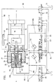
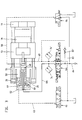
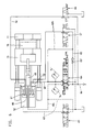
- Figures 1, 2 show the basic circuit diagram of mold clamping units, which differ in the number of their pressure or compensating cylinders and their arrangement.
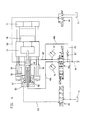
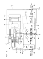
- FIGs. 3 to 6 show different switching positions of the hydraulic device when closing, locking and opening the injection mold.
- Figs. 3-6 only the parts of the hydraulic device that are used are shown, the pressure lines leading to the different cylinder spaces being drawn in a solid line and the respective return lines to the tank in dashed lines.
- the structural design of the mold clamping unit and the hydraulic device is preferably from FIGS. 1 and 2 can be seen: a stationary mold carrier 11 is attached to the machine base.
- the movable mold carrier 13 is slidably arranged on columns 16.
- the hydraulic device comprises a control pump P with control valve 164, at least one hydraulic pressure cylinder 20, 25 for building up the locking pressure for the injection mold 78 and at least one hydraulic drive cylinder with piston 47b and at least one compensating cylinder which can be acted upon on one side.
- the cylinder spaces (high pressure space 52 and low pressure space 50) of the pressure cylinder 20, 25 delimited by the pressure piston 25 can be connected to one another via controllable overflow channels 42.
- an annular piston 43 is provided which can be acted upon from a cylinder chamber 61.
- the cylinder chamber 61 is connected to the tank 71 via a line 58 which is controlled by a control slide 66.
- a hydraulic drive cylinder with stationary piston 47b lying in the axis aa of the mold clamping unit enables the injection mold 78 to be closed and opened.
- the actual cylinder of this drive cylinder is in the exemplary embodiment of FIG. 1 by the piston rod of the pressure piston 25, in the exemplary embodiment of FIG. 2 by the Piston rod of the piston 26 of the compensating cylinder 21, 26 is formed.
- a single pressure cylinder 20, 25 coaxial with the central drive cylinder and two compensating cylinders 21, 26 are provided.
- the latter are arranged diametrically to the pressure cylinder 20, 25.
- a single compensating cylinder 21, 26 coaxial with the central drive cylinder and two pressure cylinders 20, 25 are provided.
- the latter are arranged diametrically to the compensating cylinder 21, 26.
- the hydraulic drive cylinder with stationary piston 47b closes and opens the injection mold 78 in cooperation with a section voltage converter 81 and with the aid of the control valve 164 while simultaneously influencing the pressure of the piston 47b on both sides according to a quantity program.
- the one or more cylinder spaces 51 of the compensating cylinders 21, 26 are in open connection with the low-pressure space 50 or the low-pressure spaces 50.
- connection channels 48c leading from the control valve 164 to the cylinder spaces 48, 80 of the drive cylinder; 68 a pressure sensor 74, 74 'is provided.
- the connection channels 48c; 68 are over branch channels 63; 68b with the high-pressure chamber 52 and the low-pressure chamber 50 in connection.
- the branch channels mentioned are each of a spool 65; 67 masters.
- the pistons 25, 26 of the pressure cylinders 20, 25 and compensating cylinders 21, 26 are connected to the mold carrier 13 via their piston rods.
- the 4/4-way valve can be a proprotional valve with 0 overlap, the switching positions of which can be converted into one another if the cross-section changes continuously.
- the branch line 68b is connected to the section 84 of the pressure line from the control pump P to the 4/4-way valve 164 via a connecting line 83 which is provided with a check valve 83 '.
- the hydraulic device works as follows: The closing movement begins with simultaneous influencing on both sides of the stationary piston 47b, designed as a differential piston, of the drive cylinder with one-sided piston action. Thus, in this first phase of the closing movement, an increasing acceleration force can be realized up to a certain desired speed (FIG. 3). If the 4/4-way valve 164 is switched through to the left, there is a continuous changeover from direct piston action (FIG. 3) to differential switching (FIG. 4). At the beginning of this reversal, as a result of the piston of the 4/4-way valve being switched on, the much larger amount of pressure flowing back from the rear cylinder space 80 initially flows diums back to tank 71 via connection 'B' to 'T' of 4/4-way valve 164.
- the switching of the 4/4 directional valve from the middle position according to FIGS. 1, 2 to the left into the differential switching position according to FIG. 4 can be carried out both continuously in the above sense, but also in different stages.
- the switching time for the entire stroke is approximately 25 msec when switched directly.
- the transition switch position (FIG. 3) with which the closing movement begins can be of extremely short duration, that is to say a few msec. However, it can also be extended in time if necessary.
- a superimposed pressure control is connected to the speed profile during the entire closing and opening movement.
- the speed control or control triggered by pulses from the pressure sensors 74 or 74 ', changes to pressure control.
- the closing movement takes place essentially in the differential switch position, in which the 4/4-way valve is in the left position.
- the pressure medium displaced from the cylinder space 80 of the drive cylinder is directly divided into the tank 71 or via the branch passage 68b provided with the check valve 83 'and bridging the 4/4-way valve; 83 fed into the pressure line 84 between the hydraulic pump p and the 4/4-way valve 164, specifically with the pressure sensors 74; 74 '.
- the 4/4-way valve can thus be switched again to the transition circuit (FIG. 3) adjacent to the differential switch position (FIG. 4).
- the pressure medium displaced from the cylinder space 80 is introduced directly into the tank 71 via the valve channel 68 with a superimposed pressure control.
- the connecting channel 48c leading from the 4/4-way valve to the cylinder chamber 48 of the drive cylinder is connected to the high-pressure chamber 52 via the branch channel 63 controlled by the control slide 65, and the connecting channel 68 leading from the cylinder chamber 80 of the drive cylinder to the tank 71 is via the control slide 67 controlled branch channel 68b connected to the low pressure chamber 50 (Fig. 5).
- pressure medium is fed into the high pressure chamber 52 with the overflow channels 42 closed in the pressure piston 25 and a correspondingly large amount of oil is discharged from the low pressure chamber 50 via the branch line 68b and the 4/4-way valve into the tank 71. Since this last phase is extremely short, the general principle remains that the vast majority of the pressure medium remains in an internal circuit of the hydraulic system over the entire spraying cycle and only a small part reaches the tank, which is desirable for temperature compensation.
- the 4/4-way valve is switched to the right position according to FIG. 6.
- the pressure medium passes from the pump P via the pressure line 84 and the connecting channel 68 into the rear cylinder space 80 of the drive cylinder.
- the connecting duct 68 is connected to the low-pressure chamber 50, which is now used as a high-pressure chamber, via the branch duct 68b controlled by the control slide 67.
- a large amount of oil is therefore fed into the cylinder space 50 per unit of time and consequently displaced from the cylinder space 52.
- This displaced pressure medium passes through the branch channel 63 controlled by the control slide 65 into the connecting channel 48c in order to reach the tank 71 via the 4/4-way valve.
- the pressure medium displaced from the cylinder space 48 reaches the tank via the connecting channel 48c and the 4/4-way valve.
- the outflow of the pressure medium from the cylinder spaces 48, 52 can therefore take place thanks to the pressure sensor 74, 74 'with an overlying pressure control.
- the further opening of the injection mold and also the holding of the injection mold when the plastic material is injected into the injection mold 78 can be carried out in a known manner (DE 36 44 181 C1).
Abstract
Description
Die Erfindung betrifft eine Hydraulikeinrichtung entsprechend dem Oberbegriff des Anspruches 1.The invention relates to a hydraulic device according to the preamble of
Bei einer bekannten Hydraulikeinrichtung dieser Art (DE 36 44 181 C1; DE 38 44 432 C1) wird die Spritzgießform dadurch geschlossen, daß der gießformseitige Zylinderraum des Antriebszylinders über das Regelventil bei einer überlagernden Druckregelung mittels Druckfühler mit Druckmedium beschickt wird. Das bei der Schließbewegung aus dem rückwärtigen Zylinderraum des Antriebszylinders verdrängte Druckmedium gelangt über eine mit Druckfühler für eine überlagernde Druckregelung versehene Leitung und über das Regelventil zum Tank. Infolge der Differenzflächen des Druckzylinders und des Ausgleichszylinders wird beim Schließen eine geringe Menge an Druckmedium frei, das zwecks Temperaturausgleich aus dem Hochdruckraum des Druckzylinders unmittelbar zum Tank fließt.In a known hydraulic device of this type (DE 36 44 181 C1; DE 38 44 432 C1), the injection mold is closed in that the cylinder chamber of the drive cylinder on the mold side is supplied with pressure medium via the control valve in the case of a superimposed pressure control by means of a pressure sensor. The pressure medium displaced from the rear cylinder space of the drive cylinder during the closing movement reaches the tank via a line provided with a pressure sensor for an overlying pressure control and via the control valve. As a result of the differential areas of the pressure cylinder and the compensating cylinder, a small amount of pressure medium is released when closing, which flows directly from the high-pressure chamber of the pressure cylinder to the tank for temperature compensation.
Der Erfindung liegt die Aufgabe zugrunde, eine Hydraulikeinrichtung der eingangs genannten Gattung derart weiterzubilden, daß die Leistung der Kunststoff-Spritzgießmaschine bei schonenden Geschwindigkeits- und Druckprofilen der Formträgerbewegung wesentlich erhöht werden kann.The invention has for its object to develop a hydraulic device of the type mentioned in such a way that the performance of the plastic injection molding machine can be increased significantly with gentle speed and pressure profiles of the mold carrier movement.
Diese Aufgabe wird erfindungsgemäß durch die im Anspruch 1 genannten Merkmale gelöst.This object is achieved by the features mentioned in
Bei einer solchen Lösung sind die Schließewegungen beim Schließen der Formschließeinheit beschleunigt. Die hierfür erforderlichen Geschwindigkeitsprofile und Druckprofile können den jeweiligen maschinenbaulichen und spritztechnischen Erfordernissen in höherem Maße angepaßt werden. Die Schließbewegung beginnt bei gleichzeitiger beidseitiger Beeinflussung des stationären Differenzkolbens des Antriebszylinders mit einseitiger Kolbenbeaufschlagung und dadurch bedarfsweise höherer Beschleunigungskraft bis zu einer bestimmten erwünschten Geschwindigkeit (Übergangsschaltung gemäß Fig. 3). Bei weiterem Durchschalten des 4/4-Wegeventils ergibt sich ein stufenloser Übergang von der direkten Kolbenbeaufschlagung (Übergangsschaltstellung gemäß Fig. 3) auf die Differenzschaltung (Fig. 4) statt. In der ersten zeitlichen Phase dieses Übergangs fließt im Gefolge des Weiterschaltens des Kolbens des 4/4-Wegeventils zunächst noch die größere Menge an Druckmedium aus dem rückwärtigen Zylinderraum 80 des Antriebszylinders über die Verbindung 'B' zu 'T' des 4/4-Wegeventils zum Tank zurück. Die kleinere Menge an Druckmedium wird demzufolge noch über das Rückschlagventil 83' der Druckleitung 84 und damit dem gießformseitigen Zylinderraum 48 des Antriebszylinders zugeführt. Im Gefolge einer weiteren Bewegung des Kolbens des 4/4-Wegeventils in Richtung Differenz-Schaltstellung (Fig. 4) wird die rückfließende Menge an Druckmedium von 'B' zu 'T' immer geringer und die Menge an Druckmedium, welche über das Rückschlagventil 83' in die Druckleitung 84 gelangt, immer größer. Bei Erreichen der Differenzschaltung fließt kein Druckmedium mehr über die Verbindung 'B' zu 'T' des 4/4-Wegeventils zum Tank zurück; vielmehr wird das gesamte, aus dem rückwärtigen Zylinderraum 80 des Antriebszylinders verdrängte Druckmedium über das Rückschlagventil der Verbindungsleitung 83 der Druckleitung 84 zugeführt. Damit ist die maximale Schließgeschwindigkeit bei voller Differenzschaltstellung (Fig.4) erreicht. Um ein hartes Aufeinandertreffen der Gießformhälften am Ende der Schließbewegung zu vermeiden, wird die Differenzschaltstellung in der Regel in gleicher Weise wie beim allmählichen Übergang von der anfänglichen Übergangsschaltstellung (Fig. 3) in die Differenzschaltung (Fig. 4) bei annäherungsweise stufenloser Querschnittsveränderung der Durchflußöffnungen im 4/4-Wegeventil in die Übergangsschaltstellung (Fig. 3) überführt.In such a solution, the closing movements are accelerated when the mold closing unit is closed. The speed profiles and pressure profiles required for this can be adapted to a greater extent to the respective mechanical engineering and injection molding requirements. The closing movement begins with simultaneous influence on both sides of the stationary differential piston of the drive cylinder with one-sided piston action and, as a result, higher acceleration force as required up to a certain desired speed (transition circuit according to FIG. 3). If the 4/4-way valve is switched through further, there is a continuous transition from direct piston action (transition switching position according to FIG. 3) to the differential switching (FIG. 4). In the first phase of this transition, as a result of the switching of the piston of the 4/4-way valve, the larger amount of pressure medium initially flows from the
Bei der erfindungsgemäßen Ausbildung können darüber hinaus die Voraussetzungen dafür vorliegen, daß die Endphase der Schließbewegung (Übergangsschaltstellung gemäß Fig. 3) in eine mittels Druckfühler geregelte Auslaufbewegung stufenlos übergeleitet werden kann (Endschaltung gemäß Fig. 5), in welcher der Hochdruckraum des Druckzylinders bereits auf 'Zuhaltedruck' gesteuert ist, so daß die Spritzgießform bei weiterem ruhigem Lauf nahezu erschütterungsfrei schließt.In the case of the design according to the invention, the prerequisites may also exist for the final phase of the closing movement (transition switch position according to FIG. 3) to be continuously transferred to an outlet movement regulated by a pressure sensor (limit switch according to FIG. 5) in which the high-pressure chamber of the pressure cylinder is already open 'Locking pressure' is controlled so that the injection mold closes almost vibration-free when it runs smoothly.
Schließlich liegen bei der erfindungsgemäßen Ausbildung die Voraussetzungen dafür vor, daß die Spritzgießform mit großer Kraft (Aufreißbewegung gemäß Fig. 6) druckgeregelt und unter Anpassung an die jeweiligen Erfordernisse geöffnet werden kann.Finally, in the configuration according to the invention, the prerequisites are met for the injection mold to be pressure-controlled with great force (tear-open movement according to FIG. 6) and to be opened with adaptation to the respective requirements.
In Versuchen ergab sich, daß die Geschwindigkeit der Schließbewegung bei Differenzstellung im Vergleich zur bisher üblichen Schließart mit ca. 600 mm/s auf ca. 900 mm/s gesteigert werden kann. Geht man von einer Dauer des Spritzzyklus von 5-10 sec. aus, so kann sich eine Zeitersparnis im Spritzzyklus bis hin zu 10% ergeben, was bei der Vielzahl von Spritzzyklen einer im Dauerbetrieb befindlichen Spritzgießmaschine von großer Bedeutung sein kann.Experiments have shown that the speed of the closing movement in the differential position can be increased from approx. 600 mm / s to approx. 900 mm / s compared to the previously used type of closing. If one assumes a duration of the injection cycle of 5-10 seconds, this can result in time savings in the injection cycle of up to 10%, which can be of great importance given the large number of injection cycles in an injection molding machine that is in continuous operation.
All dies führt letztlich zu einem sehr erschütterungsarmen Ablauf der Spritzzyklen und vermindert trotz erhöhter 'Schußzahl' pro Zeiteinheit die mechanischen Beanspruchungen kritischer Maschinenteile. Die Hydraulikeinrichtung ist unabhängig von der Anzahl ihrer Druckzylinder bzw. Ausgleichszylinder und deren Anordnung einsetzbar.All of this ultimately leads to a very low-vibration sequence of the spraying cycles and reduces the mechanical stresses on critical machine parts despite an increased number of shots per unit of time. The hydraulic device can be used regardless of the number of its pressure cylinders or compensating cylinders and their arrangement.
Nachstehend wird die Erfindung anhand der Zeichnung erläutert.The invention is explained below with reference to the drawing.
Es zeigen:
- Fig. 1, 2 den Grundschaltplan der Hydraulikeinrichtung bei unterschiedlicher Anzahl und unterschiedlicher Anordnung der Zylinder der Formschließeinheit,
- Fig. 3, 4 die Hydraulikeinrichtung beim Schließen der Spritzgießform ohne und mit Differenzschaltung des Antriebszylinders,
- Fig. 5 das Schließen der Spritzgießform am Ende einer durch die Zuschaltung des Hochdruckraumes (52) gekennzeichneten Endschließphase und
- Fig. 6 das Öffnen der Spritzgießform mit hoher Auffahrkraft.
- 1, 2 the basic circuit diagram of the hydraulic device with different numbers and different arrangement of the cylinders of the mold clamping unit,
- 3, 4 the hydraulic device when closing the injection mold without and with differential circuit of the drive cylinder,
- 5 shows the closing of the injection mold at the end of a final closing phase characterized by the connection of the high-pressure chamber (52) and
- Fig. 6 the opening of the injection mold with high collision force.
Die Figuren 1, 2 zeigen den Grundschaltplan an Formschließeinheiten, die sich durch die Anzahl ihrer Druck- bzw. Ausgleichszylinder und deren Anordnung unterscheiden.Figures 1, 2 show the basic circuit diagram of mold clamping units, which differ in the number of their pressure or compensating cylinders and their arrangement.
Die Fign. 3 bis 6 zeigen unterschiedliche Schaltstellungen der Hydraulikeinrichtung beim Schließen, Zuhalten und Öffnen der Spritzgießform. In den Fign. 3-6 sind lediglich die in Anspruch genommenen Teile der Hydraulikeinrichtung dargestellt, wobei die zu den unterschiedlichen Zylinderräumen führenden Druckleitungen in ausgezogener Linie und die jeweiligen Rückleitungen zum Tank in gestrichelter Linienführung ausgeführt sind.The figures 3 to 6 show different switching positions of the hydraulic device when closing, locking and opening the injection mold. In Figs. 3-6 only the parts of the hydraulic device that are used are shown, the pressure lines leading to the different cylinder spaces being drawn in a solid line and the respective return lines to the tank in dashed lines.
Die bauliche Gestaltung der Formschließeinheit und der Hydraulikeinrichtung ist vorzugsweise aus den Fign. 1 und 2 erkennbar: ein stationärer Formträger 11 ist am Maschinenfuß befestigt. Der bewegbare Formträger 13 ist auf Säulen 16 verschiebbar angeordnet. Die Hydraulikeinrichtung umfaßt eine Regelpumpe P mit Regelventil 164, wenigstens einen hydraulischen Druckzylinder 20, 25 zum Aufbau des Zuhaltedruckes für die Spritzgießform 78 und wenigstens einen hydraulischen Antriebszylinder mit Kolben 47b sowie wenigstens einen einseitig beaufschlagbaren Ausgleichszylinder. Die vom Druckkolben 25 begrenzten Zylinderräume (Hochdruckraum 52 und Niederdruckraum 50) des Druckzylinders 20, 25 sind über steuerbare Überströmkanäle 42 miteinander in Verbindung setzbar. Zum Schließen und Öffnen der Überströmkanäle 42 ist ein Ringkolben 43 vorgesehen, der aus einem Zylinderraum 61 beaufschlagbar ist. Der Zylinderraum 61 steht mit dem Tank 71 über eine Leitung 58 in Verbindung, die von einem Steuerschieber 66 beherrscht ist. Ein in der Achse a-a der Formschließeinheit liegender hydraulischer Antriebszylinder mit stationärem Kolben 47b ermöglicht das Schließen und Öffnen der Spritzgießform 78. Der eigentliche Zylinder dieses Antriebszylinders ist im Ausführungsbeispiel der Fig. 1 durch die Kolbenstange des Druckkolbens 25, im Ausführungsbeispiel der Fig. 2 durch die Kolbenstange des Kolbens 26 des Ausgleichszylinders 21, 26 gebildet. Im Beispiel der Fig. 1 sind ein einziger, zum zentralen Antriebszylinder koaxialer Druckzylinder 20, 25 und zwei Ausgleichszylinder 21, 26 vorgesehen. Letztere sind diametral zum Druckzylinder 20, 25 angeordnet. Im Beispiel der Fig. 2 sind ein einziger, zum zentralen Antriebszylinder koaxialer Ausgleichszylinder 21, 26 und zwei Druckzylinder 20, 25 vorgesehen. Letztere sind diametral zum Ausgleichszylinder 21, 26 angeordnet. Der hydraulische Antriebszylinder mit stationärem Kolben 47b schließt und öffnet die Spritzgießform 78 im Zusammenwirken mit einem Streckenspannungswandler 81 und mit Hilfe des Regelventils 164 bei gleichzeitiger, beidseitiger Druckbeeinflussung des Kolbens 47b nach einem Mengenprogramm. Der bzw. die Zylinderräume 51 der Ausgleichszylinder 21, 26 stehen mit dem Niederdruckraum 50 bzw. den Niederdruckräumen 50 in offener Verbindung. In dem vom Regelventil 164 zu den Zylinderräumen 48, 80 des Antriebszylinders führenden Verbindungskanälen 48c; 68 ist je ein Druckfühler 74, 74' vorgesehen. Die genannten Verbindungskanäle 48c; 68 stehen über Zweigkanäle 63; 68b mit dem Hochdruckraum 52 und dem Niederdruckraum 50 in Verbindung. Die genannten Zweigkanäle sind je von einem Steuerschieber 65; 67 beherrscht. Die Kolben 25, 26 von Druckzylinder 20, 25 und Ausgleichzylinder 21, 26 stehen über ihre Kolbenstangen mit dem Formträger 13 in Verbindung.The structural design of the mold clamping unit and the hydraulic device is preferably from FIGS. 1 and 2 can be seen: a
Das 4/4-Wegeventil kann ein Proprotionalventil mit 0-Überschneidung sein, dessen Schaltstellungen bei stufenloser Querschnittsveränderung ineinander überführbar sind.The 4/4-way valve can be a proprotional valve with 0 overlap, the switching positions of which can be converted into one another if the cross-section changes continuously.
Die Zweigleitung 68b steht mit dem von der Regelpumpe P zum 4/4-Wegeventil 164 stehenden Abschnitt 84 der Druckleitung über eine Verbindungsleitung 83 in Verbindung, welche mit einem Rückschlagventil 83' versehen ist.The
In allen Schaltstellungen der Schließbewegung ist der stationäre Kolben 47b des Antriebszylinders mit Kolben 47b aus dem gießformseitigen Zylinderraum 48 beaufschlagt.In all switching positions of the closing movement, the
Die Hydraulikeinrichtung arbeitet wie folgt: Die Schließbewegung beginnt bei gleichzeitiger beidseitiger Beeinflussung des stationären, als Differenzkolben ausgebildeten Kolbens 47b des Antriebszylinders mit einseitiger Kolbenbeaufschlagung. So-mit kann in dieser ersten Phase der Schließbewegung eine zunehmende Beschleunigungskraft bis zu einer bestimmten erwünschten Geschwin digkeit realisiert werden (Fig. 3). Bei weiterem Durchschalten des 4/4-Wegeventils 164 nach links findet eine stufenlose Umsteuerung von direkter Kolbenbeaufschlagung (Fig. 3) auf Differenzschaltung (Fig. 4) statt. Am Anfang dieser Umsteuerung fließt im Gefolge eines Weiterschaltens des Kolbens des 4/4-Wegeventils zunächst noch die weitaus größere Menge des aus dem rückwärtigen Zylinderraum 80 zurückfließenden Druckmediums über die Verbindung 'B' zu 'T' des 4/4-Wegeventils 164 zum Tank 71 zurück. Die kleinere Menge an Druckmedium wird noch über das Rückschlagventil 83' der Druckleitung 84 und damit dem Zylinderraum 48 zugeführt. Im Gefolge einer weiteren Vrschiebung des Kolbens des 4/4-Wegeventils in Richtung auf die Differenzschaltsstellung mit höherer Schließgeschwindigkeit wird die rückfließende Menge an Druckmedium von 'B' zu 'T' des 4/4 Wegeventils immer geringer und die Menge an Druckmedium, welche über das Rückschlagventil 83' in die Druckleitung 84 gelangt, immer größer. Bei Erreichen der Differenzschaltstellung gelangt die gesamte, aus dem rückwärtigen Zylinderraum 80 verdrängte Menge an Druckmedium über das Rückschlagventil in die Druckleitung 84 und damit zum 4/4-Wegeventil 164, so daß die volle Differenzschaltstellung mit maximaler Schließgeschwindigkeit erreicht ist. In diesem Zusammenhang ist darauf hinzuweisen, daß das Durchschalten des 4/4-Wegeventils von der Mittelstellung gemäß Figuren 1, 2 nach links in die Differenzschaltstellung gemäß Fig. 4 sowohl stufenlos im obigen Sinne, aber auch in verschiedenen Stufen ausgeführt werden kann. Die Schaltzeit für den Gesamthub beträgt bei direkter Durchschaltung etwa 25 msec. Dies bedeutet, daß die Übergangsschaltstellung (Fig. 3), mit welcher die Schließbewegung beginnt, von extrem kurzer Dauer sein kann, d.h. wenige msec betragen kann. Sie kann aber auch bedarfsweise zeitlich ausgedehnt werden.The hydraulic device works as follows: The closing movement begins with simultaneous influencing on both sides of the
Während der gesamten Schließ- und Öffnungsbewegung ist dem Geschwindigkeitsprofil eine überlagerte Druckregelung zugeschaltet. Bei Erreichung der programmierten Druckgröße geht die Geschwindigkeitsregelung bzw. -Steuerung, ausgelöst durch Impulse der Druckfühler 74 bzw. 74' in eine Druckregelung über.A superimposed pressure control is connected to the speed profile during the entire closing and opening movement. When the programmed pressure variable is reached, the speed control or control, triggered by pulses from the
In aller Regel vollzieht sich die Schließbewegung im wesentlichen bei Differenzschaltstellung, in welcher das 4/4-Wegeventil sich in Linksstellung befindet. In wahlweiser zeitlicher Aufteilung wird je nach Geschwindigkeitserfordernis das aus dem Zylinderraum 80 des Antriebszylinders verdrängte Druckmedium direkt zum Tank 71 oder über den mit Rückschlagventil 83' versehenen das 4/4-Wegeventil überbrückenden Zweigkanal 68b; 83 in die Druckleitung 84 zwischen der Hydraulikpumpe p und dem 4/4-Wegeventil 164 eingespeist, und zwar bei überlagerter Druckregelung durch die Druckfühler 74; 74'.As a rule, the closing movement takes place essentially in the differential switch position, in which the 4/4-way valve is in the left position. Depending on the speed requirement, the pressure medium displaced from the
Nach der Differenzschaltstellung kann also das 4/4-Wegeventil erneut in die der Differenzschaltstellung (Fig. 4) benachbarte Übergangsschaltung (Fig. 3) geschaltet werden. In dieser Übergangsschaltstellung wird das aus dem Zylinderraum 80 verdrängte Druckmedium über den Ventilkanal 68 bei einer überlagerten Druckregelung unmittelbar in den Tank 71 eingeleitet.After the differential switch position, the 4/4-way valve can thus be switched again to the transition circuit (FIG. 3) adjacent to the differential switch position (FIG. 4). In this transition switching position, the pressure medium displaced from the
In einem allerletzten Abschnitt der Schließbewegung können bei aufrecht erhaltener Übergangsschaltstellung (Fig. 3) zusätzlich folgende Verbindungen hergestellt werden:In a very last section of the closing movement, the following connections can also be made with the transition switch position maintained (FIG. 3):
Der vom 4/4-Wegeventil zum Zylinderraum 48 des Antriebszylinders führende Verbindungskanal 48c wird über den vom Steuerschieber 65 beherrschten Zweigkanal 63 mit dem Hochdruckraum 52 in Verbindung gesetzt und der vom Zylinderraum 80 des Antriebszylinders zum Tank 71 führende Verbindungskanal 68 wird über den vom Steuerschieber 67 beherrschten Zweigkanal 68b mit dem Niederdruckraum 50 in Verbindung gesetzt (Fig. 5). In dieser allerletzten, relativ langsamen Schließphase wird Druckmedium in den Hochdruckraum 52 bei geschlossenen Überströmkanälen 42 in Druckkolben 25 eingespeist und eine entsprechend große Ölmenge aus dem Niederdruckraum 50 über die Zweigleitung 68b und das 4/4-Wegeventil in den Tank 71 abgeleitet. Da diese letzte Phase extrem kurz ist, bleibt insgesamt der Grundsatz gewahrt, daß der ganz überwiegende Teil des Druckmediums über den gesamten Spritzzyklus in einem inneren Kreislauf des Hydrauliksystems verbleibt und nur ein geringfügiger Teil in den Tank gelangt, was zwecks Temperaturausgleich erwünscht ist.The connecting
Ist es erforderlich die Spritzgießform mit großer Kraft zu öffnen, so wird das 4/4-Wegeventil in Rechtsstellung gemäß Fig. 6 geschaltet. In dieser Stellung gelangt das Druckmedium von der Pumpe P über die Druckleitung 84 und den Verbindungskanal 68 in den rückwärtigen Zylinderraum 80 des Antriebszylinders. Gleichzeitig ist der Verbindungskanal 68 über den vom Steuerschieber 67 beherrschten Zweigkanal 68b mit dem nunmehr als Hochdruckraum dienenden Niederdruckraum 50 in Verbindung gesetzt. In dieser allerletzten Phase wird daher pro Zeiteinheit eine große Ölmenge in den Zylinderraum 50 eingespeist und demzufolge aus dem Zylinderraum 52 verdrängt. Dieses verdrängte Druckmedium gelangt über den vom Steuerschieber 65 beherrschten Zweigkanal 63 in den Verbindungskanal 48c, um über das 4/4-Wegeventil in den Tank 71 zu gelangen. Gleichzeitig gelangt das aus dem Zylinderraum 48 verdrängte Druckmedium über den Verbindungskanal 48c und das 4/4-Wegeventil in den Tank. Der Abfluß des Druckmediums aus den Zylinderräumen 48, 52 kann daher dank des Druckfühlers 74, 74' mit einer überlagernden Druckregelung erfolgen. Das weitere Öffnen der Spritzgießform sowie auch das Zuhalten der Spritzgießform beim Einspritzen des Kunststoffmaterials in die Spritzgießform 78 können in bekannter Weise (DE 36 44 181 C1) durchgeführt werden.If it is necessary to open the injection mold with great force, the 4/4-way valve is switched to the right position according to FIG. 6. In this position, the pressure medium passes from the pump P via the
Claims (6)
Applications Claiming Priority (2)
| Application Number | Priority Date | Filing Date | Title |
|---|---|---|---|
| DE4018334 | 1990-06-08 | ||
| DE4018334A DE4018334C1 (en) | 1990-06-08 | 1990-06-08 | Hydraulic appts. for mould closing unit of injection moulder - includes pump control valve on mould closure unit, hydraulic cylinder(s) controlled by 4-4 way valve |
Publications (3)
| Publication Number | Publication Date |
|---|---|
| EP0462046A2 EP0462046A2 (en) | 1991-12-18 |
| EP0462046A3 EP0462046A3 (en) | 1993-01-13 |
| EP0462046B1 true EP0462046B1 (en) | 1995-05-17 |
Family
ID=6408010
Family Applications (1)
| Application Number | Title | Priority Date | Filing Date |
|---|---|---|---|
| EP91710013A Expired - Lifetime EP0462046B1 (en) | 1990-06-08 | 1991-04-20 | Hydraulic device at the die closing unit of a plastics injection moulding machine |
Country Status (7)
| Country | Link |
|---|---|
| US (1) | US5129806A (en) |
| EP (1) | EP0462046B1 (en) |
| JP (1) | JPH0655398B2 (en) |
| AT (1) | ATE122599T1 (en) |
| CA (1) | CA2043151A1 (en) |
| DE (2) | DE4018334C1 (en) |
| ES (1) | ES2073146T3 (en) |
Families Citing this family (42)
| Publication number | Priority date | Publication date | Assignee | Title |
|---|---|---|---|---|
| DE4209392C2 (en) * | 1992-03-23 | 1995-10-12 | Krauss Maffei Ag | Mold closing device for an injection molding machine |
| US5634334A (en) * | 1992-10-14 | 1997-06-03 | Hehl; Karl | Hydraulic device for use in a production machine |
| DE4234647C1 (en) * | 1992-10-14 | 1994-01-27 | Karl Hehl | Hydraulic device on an injection molding machine for processing plastics or the like |
| ATE183131T1 (en) * | 1994-04-02 | 1999-08-15 | Karl Hehl | MOLD CLOSING UNIT FOR AN INJECTION MOLDING MACHINE AND METHOD FOR OPERATING THE SAME |
| JP3262215B2 (en) * | 1997-08-18 | 2002-03-04 | 日精樹脂工業株式会社 | Mold clamping method of direct pressure mold clamping device |
| JP3247319B2 (en) * | 1997-08-26 | 2002-01-15 | 株式会社名機製作所 | Method and device for controlling clamping pressure in direct pressure type clamping device |
| DE10135516A1 (en) * | 2000-08-08 | 2002-06-20 | Mannesmann Rexroth Ag | Drive for closure-, injection- or ejection units of pressure injection molding machine has electric motor selectively displacing nested concentric piston-cylinder arrangement |
| DE10051255C1 (en) * | 2000-10-16 | 2002-05-29 | Karl Hehl | Closure mechanism for a hydraulically operated plastics injection molding machine has tool closure, clamping and compensating cylinders concentric with a central axis |
| JP2002240116A (en) * | 2001-02-19 | 2002-08-28 | Sato Tekkosho:Kk | Mold clamping device for injection molding and injection holding machine |
| WO2002076703A2 (en) * | 2001-03-21 | 2002-10-03 | Bosch Rexroth Ag | Electromechanical clamping device |
| DE10220406B4 (en) * | 2001-07-02 | 2011-02-03 | Bosch Rexroth Aktiengesellschaft | Driving device for a moving part, in particular mold clamping device for an injection molding machine, and method for operating such a drive device |
| DE10209921C1 (en) * | 2002-03-07 | 2003-10-30 | Karl Hehl | Locking device on a plastic injection molding machine |
| DE10215072A1 (en) * | 2002-04-05 | 2003-10-30 | Billion Sa | Hydraulic device for moving a machine part back and forth |
| US20040022894A1 (en) * | 2002-07-31 | 2004-02-05 | Kim Jong Hwan | Molding machine closing apparatus having movable platen both guided and driven by multiple actuators |
| JP2004299269A (en) * | 2003-03-31 | 2004-10-28 | Aoki Technical Laboratory Inc | Mold clamping device |
| US7775966B2 (en) | 2005-02-24 | 2010-08-17 | Ethicon Endo-Surgery, Inc. | Non-invasive pressure measurement in a fluid adjustable restrictive device |
| US8016744B2 (en) | 2005-02-24 | 2011-09-13 | Ethicon Endo-Surgery, Inc. | External pressure-based gastric band adjustment system and method |
| US7927270B2 (en) | 2005-02-24 | 2011-04-19 | Ethicon Endo-Surgery, Inc. | External mechanical pressure sensor for gastric band pressure measurements |
| US8066629B2 (en) | 2005-02-24 | 2011-11-29 | Ethicon Endo-Surgery, Inc. | Apparatus for adjustment and sensing of gastric band pressure |
| US7775215B2 (en) | 2005-02-24 | 2010-08-17 | Ethicon Endo-Surgery, Inc. | System and method for determining implanted device positioning and obtaining pressure data |
| US7699770B2 (en) | 2005-02-24 | 2010-04-20 | Ethicon Endo-Surgery, Inc. | Device for non-invasive measurement of fluid pressure in an adjustable restriction device |
| US7658196B2 (en) | 2005-02-24 | 2010-02-09 | Ethicon Endo-Surgery, Inc. | System and method for determining implanted device orientation |
| DE102005053802A1 (en) * | 2005-11-11 | 2007-05-16 | Demag Ergotech Gmbh | Closing device for an injection molding machine |
| DE102006009900B4 (en) * | 2006-03-03 | 2008-06-26 | Kraussmaffei Technologies Gmbh | Integrated system device for producing composite bodies |
| US8152710B2 (en) | 2006-04-06 | 2012-04-10 | Ethicon Endo-Surgery, Inc. | Physiological parameter analysis for an implantable restriction device and a data logger |
| US8870742B2 (en) | 2006-04-06 | 2014-10-28 | Ethicon Endo-Surgery, Inc. | GUI for an implantable restriction device and a data logger |
| US8187163B2 (en) | 2007-12-10 | 2012-05-29 | Ethicon Endo-Surgery, Inc. | Methods for implanting a gastric restriction device |
| US8100870B2 (en) | 2007-12-14 | 2012-01-24 | Ethicon Endo-Surgery, Inc. | Adjustable height gastric restriction devices and methods |
| US8142452B2 (en) | 2007-12-27 | 2012-03-27 | Ethicon Endo-Surgery, Inc. | Controlling pressure in adjustable restriction devices |
| US8377079B2 (en) | 2007-12-27 | 2013-02-19 | Ethicon Endo-Surgery, Inc. | Constant force mechanisms for regulating restriction devices |
| US8591395B2 (en) | 2008-01-28 | 2013-11-26 | Ethicon Endo-Surgery, Inc. | Gastric restriction device data handling devices and methods |
| US8192350B2 (en) | 2008-01-28 | 2012-06-05 | Ethicon Endo-Surgery, Inc. | Methods and devices for measuring impedance in a gastric restriction system |
| US8337389B2 (en) | 2008-01-28 | 2012-12-25 | Ethicon Endo-Surgery, Inc. | Methods and devices for diagnosing performance of a gastric restriction system |
| US7844342B2 (en) | 2008-02-07 | 2010-11-30 | Ethicon Endo-Surgery, Inc. | Powering implantable restriction systems using light |
| US8221439B2 (en) | 2008-02-07 | 2012-07-17 | Ethicon Endo-Surgery, Inc. | Powering implantable restriction systems using kinetic motion |
| US8114345B2 (en) | 2008-02-08 | 2012-02-14 | Ethicon Endo-Surgery, Inc. | System and method of sterilizing an implantable medical device |
| US8057492B2 (en) | 2008-02-12 | 2011-11-15 | Ethicon Endo-Surgery, Inc. | Automatically adjusting band system with MEMS pump |
| US8591532B2 (en) | 2008-02-12 | 2013-11-26 | Ethicon Endo-Sugery, Inc. | Automatically adjusting band system |
| US8034065B2 (en) | 2008-02-26 | 2011-10-11 | Ethicon Endo-Surgery, Inc. | Controlling pressure in adjustable restriction devices |
| US8187162B2 (en) | 2008-03-06 | 2012-05-29 | Ethicon Endo-Surgery, Inc. | Reorientation port |
| US8233995B2 (en) | 2008-03-06 | 2012-07-31 | Ethicon Endo-Surgery, Inc. | System and method of aligning an implantable antenna |
| WO2011066799A1 (en) * | 2009-12-04 | 2011-06-09 | Huang Buming | Mold clamping device |
Family Cites Families (6)
| Publication number | Priority date | Publication date | Assignee | Title |
|---|---|---|---|---|
| US3677685A (en) * | 1970-04-22 | 1972-07-18 | Katashi Aoki | Mold clamping mechanism of injection molding machine |
| DE3044137C2 (en) * | 1980-11-24 | 1985-01-31 | Karl 7298 Loßburg Hehl | Mold clamping unit for receiving a plastic injection mold |
| DE3238111C1 (en) * | 1982-10-14 | 1984-03-29 | Karl 7298 Loßburg Hehl | Hydraulic device for the mold clamping unit of a plastic injection molding machine |
| DE3644181C1 (en) * | 1986-12-23 | 1988-04-28 | Karl Hehl | Hydraulic device for the mold clamping unit of a plastic injection molding machine |
| JPH068021B2 (en) * | 1987-02-27 | 1994-02-02 | 青木 茂人 | Clamping mechanism of injection molding machine |
| DE3844432C1 (en) * | 1988-12-31 | 1990-01-25 | Karl 7298 Lossburg De Hehl |
-
1990
- 1990-06-08 DE DE4018334A patent/DE4018334C1/en not_active Expired - Lifetime
-
1991
- 1991-04-20 AT AT91710013T patent/ATE122599T1/en not_active IP Right Cessation
- 1991-04-20 DE DE59105492T patent/DE59105492D1/en not_active Expired - Fee Related
- 1991-04-20 EP EP91710013A patent/EP0462046B1/en not_active Expired - Lifetime
- 1991-04-20 ES ES91710013T patent/ES2073146T3/en not_active Expired - Lifetime
- 1991-05-22 JP JP3218158A patent/JPH0655398B2/en not_active Expired - Lifetime
- 1991-05-23 CA CA002043151A patent/CA2043151A1/en not_active Abandoned
- 1991-06-07 US US07/711,986 patent/US5129806A/en not_active Expired - Fee Related
Also Published As
| Publication number | Publication date |
|---|---|
| CA2043151A1 (en) | 1991-12-09 |
| ATE122599T1 (en) | 1995-06-15 |
| EP0462046A2 (en) | 1991-12-18 |
| JPH04232012A (en) | 1992-08-20 |
| DE4018334C1 (en) | 1991-11-07 |
| EP0462046A3 (en) | 1993-01-13 |
| JPH0655398B2 (en) | 1994-07-27 |
| US5129806A (en) | 1992-07-14 |
| DE59105492D1 (en) | 1995-06-22 |
| ES2073146T3 (en) | 1995-08-01 |
Similar Documents
| Publication | Publication Date | Title |
|---|---|---|
| EP0462046B1 (en) | Hydraulic device at the die closing unit of a plastics injection moulding machine | |
| EP0272626B1 (en) | Hydraulic apparatus for the mould closing unit of a plastic injection-moulding machine | |
| DE3238111C1 (en) | Hydraulic device for the mold clamping unit of a plastic injection molding machine | |
| DE2806051C2 (en) | Casting drive of a die casting machine | |
| DE2603891C3 (en) | Drive for moving an injection piston of a die casting machine | |
| DE7905666U1 (en) | DEVICE FOR MIXING A PLASTIC MIXTURE | |
| DE3307582A1 (en) | HYDRAULIC BRAKE VALVE ARRANGEMENT | |
| EP2384249A1 (en) | Arrangement for a die casting machine and method for operating a drive piston of the die casting machine | |
| EP0465474B1 (en) | Control arrangement for a two-cylinder pump for thick materials | |
| DE2704326A1 (en) | PRESSURE MEDIUM FLOW CONTROL | |
| DE2314111C3 (en) | Control device for a working piston of an engine that can be acted upon alternately on both sides | |
| DE2505648B2 (en) | CONTROL DEVICE FOR AN INJECTION DEVICE FOR INJECTION MOLDING MACHINES | |
| DE4300835C2 (en) | Drive for the axial movement of a plasticizing screw in an injection molding machine | |
| EP1814708A1 (en) | Plasticizing and injecting device | |
| DE3404927C2 (en) | Hydraulic control device for the injection unit of a plastic injection molding machine | |
| DE10138026C2 (en) | Pneumatic drive control for controlling the movement of pneumatic drives | |
| CH679843A5 (en) | ||
| DE3427327A1 (en) | Mixing head for generating a preferably chemically reactive mixture of at least two plastic components | |
| DE2447964B2 (en) | Method and device for die casting with a horizontal cold chamber machine | |
| EP0220248B1 (en) | Device for adjusting the circuit amplification of a servo-regulating circuit | |
| EP0766009B1 (en) | System for controlling a hydraulic motor | |
| DE3427326A1 (en) | Mixing head for producing a preferably chemically reactive mixture of at least two plastics components | |
| DE19537109A1 (en) | Electro-hydraulic drive device for the blow mandrel of a blow molding machine | |
| EP1179408B1 (en) | Driving mechanism for the movable platen of an injection moulding machine | |
| EP1328392B1 (en) | Closing device on a plastic injection moulding machine |
Legal Events
| Date | Code | Title | Description |
|---|---|---|---|
| PUAI | Public reference made under article 153(3) epc to a published international application that has entered the european phase |
Free format text: ORIGINAL CODE: 0009012 |
|
| AK | Designated contracting states |
Kind code of ref document: A2 Designated state(s): AT CH DE ES FR GB IT LI NL |
|
| PUAL | Search report despatched |
Free format text: ORIGINAL CODE: 0009013 |
|
| AK | Designated contracting states |
Kind code of ref document: A3 Designated state(s): AT CH DE ES FR GB IT LI NL |
|
| 17P | Request for examination filed |
Effective date: 19930203 |
|
| 17Q | First examination report despatched |
Effective date: 19940609 |
|
| GRAA | (expected) grant |
Free format text: ORIGINAL CODE: 0009210 |
|
| AK | Designated contracting states |
Kind code of ref document: B1 Designated state(s): AT CH DE ES FR GB IT LI NL |
|
| REF | Corresponds to: |
Ref document number: 122599 Country of ref document: AT Date of ref document: 19950615 Kind code of ref document: T |
|
| REF | Corresponds to: |
Ref document number: 59105492 Country of ref document: DE Date of ref document: 19950622 |
|
| ET | Fr: translation filed | ||
| ITF | It: translation for a ep patent filed |
Owner name: CALVANI SALVI E VERONELLI S.R.L. |
|
| GBT | Gb: translation of ep patent filed (gb section 77(6)(a)/1977) |
Effective date: 19950612 |
|
| REG | Reference to a national code |
Ref country code: ES Ref legal event code: FG2A Ref document number: 2073146 Country of ref document: ES Kind code of ref document: T3 |
|
| PLBE | No opposition filed within time limit |
Free format text: ORIGINAL CODE: 0009261 |
|
| STAA | Information on the status of an ep patent application or granted ep patent |
Free format text: STATUS: NO OPPOSITION FILED WITHIN TIME LIMIT |
|
| 26N | No opposition filed | ||
| PGFP | Annual fee paid to national office [announced via postgrant information from national office to epo] |
Ref country code: NL Payment date: 19970429 Year of fee payment: 7 |
|
| PGFP | Annual fee paid to national office [announced via postgrant information from national office to epo] |
Ref country code: ES Payment date: 19970430 Year of fee payment: 7 |
|
| PG25 | Lapsed in a contracting state [announced via postgrant information from national office to epo] |
Ref country code: ES Free format text: LAPSE BECAUSE OF EXPIRATION OF PROTECTION Effective date: 19980421 |
|
| PG25 | Lapsed in a contracting state [announced via postgrant information from national office to epo] |
Ref country code: NL Free format text: LAPSE BECAUSE OF NON-PAYMENT OF DUE FEES Effective date: 19981101 |
|
| NLV4 | Nl: lapsed or anulled due to non-payment of the annual fee |
Effective date: 19981101 |
|
| PGFP | Annual fee paid to national office [announced via postgrant information from national office to epo] |
Ref country code: DE Payment date: 19990318 Year of fee payment: 9 |
|
| PGFP | Annual fee paid to national office [announced via postgrant information from national office to epo] |
Ref country code: GB Payment date: 19990401 Year of fee payment: 9 |
|
| PGFP | Annual fee paid to national office [announced via postgrant information from national office to epo] |
Ref country code: FR Payment date: 19990420 Year of fee payment: 9 |
|
| PGFP | Annual fee paid to national office [announced via postgrant information from national office to epo] |
Ref country code: CH Payment date: 19990422 Year of fee payment: 9 Ref country code: AT Payment date: 19990422 Year of fee payment: 9 |
|
| REG | Reference to a national code |
Ref country code: ES Ref legal event code: FD2A Effective date: 20000301 |
|
| PG25 | Lapsed in a contracting state [announced via postgrant information from national office to epo] |
Ref country code: GB Free format text: LAPSE BECAUSE OF NON-PAYMENT OF DUE FEES Effective date: 20000420 Ref country code: AT Free format text: LAPSE BECAUSE OF NON-PAYMENT OF DUE FEES Effective date: 20000420 |
|
| PG25 | Lapsed in a contracting state [announced via postgrant information from national office to epo] |
Ref country code: LI Free format text: LAPSE BECAUSE OF NON-PAYMENT OF DUE FEES Effective date: 20000430 Ref country code: CH Free format text: LAPSE BECAUSE OF NON-PAYMENT OF DUE FEES Effective date: 20000430 |
|
| GBPC | Gb: european patent ceased through non-payment of renewal fee |
Effective date: 20000420 |
|
| REG | Reference to a national code |
Ref country code: CH Ref legal event code: PL |
|
| PG25 | Lapsed in a contracting state [announced via postgrant information from national office to epo] |
Ref country code: FR Free format text: LAPSE BECAUSE OF NON-PAYMENT OF DUE FEES Effective date: 20001229 |
|
| PG25 | Lapsed in a contracting state [announced via postgrant information from national office to epo] |
Ref country code: DE Free format text: LAPSE BECAUSE OF NON-PAYMENT OF DUE FEES Effective date: 20010201 |
|
| REG | Reference to a national code |
Ref country code: FR Ref legal event code: ST |
|
| PG25 | Lapsed in a contracting state [announced via postgrant information from national office to epo] |
Ref country code: IT Free format text: LAPSE BECAUSE OF NON-PAYMENT OF DUE FEES Effective date: 20050420 |