EP0459869B1 - Verfahren und Vorrichtung zur automatischen Regelung von Richtwalzen - Google Patents
Verfahren und Vorrichtung zur automatischen Regelung von Richtwalzen Download PDFInfo
- Publication number
- EP0459869B1 EP0459869B1 EP91401318A EP91401318A EP0459869B1 EP 0459869 B1 EP0459869 B1 EP 0459869B1 EP 91401318 A EP91401318 A EP 91401318A EP 91401318 A EP91401318 A EP 91401318A EP 0459869 B1 EP0459869 B1 EP 0459869B1
- Authority
- EP
- European Patent Office
- Prior art keywords
- product
- straightening
- rollers
- diameter
- roller
- Prior art date
- Legal status (The legal status is an assumption and is not a legal conclusion. Google has not performed a legal analysis and makes no representation as to the accuracy of the status listed.)
- Expired - Lifetime
Links
- 238000000034 method Methods 0.000 title claims abstract description 9
- 230000004044 response Effects 0.000 claims description 8
- 238000011144 upstream manufacturing Methods 0.000 claims description 8
- 230000004048 modification Effects 0.000 claims description 2
- 238000012986 modification Methods 0.000 claims description 2
- 229910000831 Steel Inorganic materials 0.000 description 9
- 239000010959 steel Substances 0.000 description 9
- 238000006073 displacement reaction Methods 0.000 description 3
- 230000009471 action Effects 0.000 description 2
- 238000005452 bending Methods 0.000 description 2
- 230000000903 blocking effect Effects 0.000 description 2
- 239000012530 fluid Substances 0.000 description 2
- 230000003321 amplification Effects 0.000 description 1
- 230000008859 change Effects 0.000 description 1
- 230000003247 decreasing effect Effects 0.000 description 1
- 230000001939 inductive effect Effects 0.000 description 1
- 239000002184 metal Substances 0.000 description 1
- 230000007935 neutral effect Effects 0.000 description 1
- 238000003199 nucleic acid amplification method Methods 0.000 description 1
- 210000000056 organ Anatomy 0.000 description 1
- 230000008569 process Effects 0.000 description 1
- 230000009467 reduction Effects 0.000 description 1
- 239000000523 sample Substances 0.000 description 1
Images


Classifications
-
- B—PERFORMING OPERATIONS; TRANSPORTING
- B21—MECHANICAL METAL-WORKING WITHOUT ESSENTIALLY REMOVING MATERIAL; PUNCHING METAL
- B21F—WORKING OR PROCESSING OF METAL WIRE
- B21F1/00—Bending wire other than coiling; Straightening wire
- B21F1/02—Straightening
-
- B—PERFORMING OPERATIONS; TRANSPORTING
- B21—MECHANICAL METAL-WORKING WITHOUT ESSENTIALLY REMOVING MATERIAL; PUNCHING METAL
- B21D—WORKING OR PROCESSING OF SHEET METAL OR METAL TUBES, RODS OR PROFILES WITHOUT ESSENTIALLY REMOVING MATERIAL; PUNCHING METAL
- B21D3/00—Straightening or restoring form of metal rods, metal tubes, metal profiles, or specific articles made therefrom, whether or not in combination with sheet metal parts
- B21D3/02—Straightening or restoring form of metal rods, metal tubes, metal profiles, or specific articles made therefrom, whether or not in combination with sheet metal parts by rollers
- B21D3/05—Straightening or restoring form of metal rods, metal tubes, metal profiles, or specific articles made therefrom, whether or not in combination with sheet metal parts by rollers arranged on axes rectangular to the path of the work
Definitions
- roller dressers It is also known to produce such roller dressers with devices which make it possible to modify the position of at least some of the rollers in order to adapt the dresser to different products to be dressed.
- the present invention relates to a method and a device which allow automatic adjustment of the position of the rollers so as to constantly obtain a correct dressing of the product to be dressed (see for example DE-A-1 752 406).
- the invention is particularly advantageous in the case where products which have large variations in cross-sections are erected, such as for example concrete steels, of which, as is well known, correct dressing is particularly difficult to implement. .
- the subject of the present invention is a process for automatic adjustment of the position of at least one dresser roller of a roller dresser, with a view to obtaining the correct dressing of an elongated product which may have variations in sections, characterized by the fact that, during the dressing operation, the diameter of the product to be dressed is measured in a dressing plane perpendicular to the axes of the dressing rollers and that, as a function of the diameter thus determined, the positioning of at least one of the dressing rollers, this positioning corresponding to the correct dressing of an elongated product whose diameter in the dressing plane is equal to the measured diameter.
- the diameter of the elongated product is measured upstream of at least one group of rollers which participate in the dressing in the plane considered.
- the response time of the positioning device of the roller (s) as a function of the diameter of the product to be straightened is determined so that it corresponds substantially to the duration of the path of the product to be drawn between the place where its diameter is measured and the place where the positioning of at least one dressing roller furthest downstream whose position is adjusted.
- each trainer must have an automatic adjustment operating according to the method of the invention.
- the present invention also relates to an automatic device for adjusting the position of at least one dressing roller of a roller dressing machine to obtain the straightness of the product to be dressed despite the variations in diameter of the latter, device characterized by the fact that it comprises in combination: a feeler device for determining, during the dressing operation, the diameter of the product to be dressed in a dressing plane perpendicular to the axes of the rollers; means for modifying the positioning of at least one of the dressing rollers; and a servo device making it possible to modify the position of the dressing roller (s) as a function of the diameter of the product to be dressing measured by the feeler device.
- the feeler device is located upstream of the dresser, or between the dresser rollers but upstream of at least some dresser rollers whose position is automatically adjusted.
- the feeler member can be constituted by two rollers which bear on either side of the product to be straightened or else using a feeler roller which bears on the product to be straightened opposite. a dressing roller.
- a feeler roller which has a V-shaped section open at an angle of about 100 to 120 ° which generally corresponds to the profile of the dresser rollers.
- the servo device which connects the feeler device to the dressing roller (s) whose position can be modified, to carry out the presetting of the dresser for a product to be dressed having a given diameter and to determine the variations in the preset position of the positionable roller (s) as a function of the variation in diameter of the product to be dressed.
- the response time of the servo-control as a function of the running speed of the product to be dressed, this response time possibly being advantageously substantially equal to the time that the elongated product takes to travel the distance between the feeler device and the most downstream roller (s) whose position is adjusted.
- the blocking roller or rollers are located among the last three rollers arranged downstream of the straightener.
- the position of all the dressing rollers is modified according to variations in the diameter of the product to be dressed.
- the servo device between the feeler which determines the diameter of the wire and the dresser roller (s) which can be moved can be constituted by a purely mechanical means or preferably by a hydraulic, electric or hydro-electric system.
- FIG. 1 shows a feeler device which makes it possible to determine the diameter of the product to be dressed 1 according to the dressing plane at a position situated for example upstream of the dresser or between two dresser rollers of the latter.
- This feeler device is constituted by a support 2 articulated at 3 on a fixed axis and which supports an oscillating lever 4 articulated at 5.
- the support 2 is provided with a feeler roller 6 while the lever 4 is provided with a feeler roller 7.
- the rollers 6 and 7 are intended to be placed on either side of the product to be straightened 1 which may be by example consisting of concrete steel.
- the feeler rollers 6 and 7 are provided with bi-conical grooves with an open angle of approximately 100 to 120 °.
- a return spring 8 is disposed between the support 2 and the lever 4 so as to apply the rollers 6 and 7 against each other by pinching the product to be straightened 1.
- a part 9 provided with an orifice and integral with the support 2 is held between two springs 10 and 11 which are threaded on a bolt 12 while being compressed by a nut 13.
- the bolt 12 is supported by a part 14 integral with the frame of the blocker.
- the feeler device is supported by the spring 10 which in cooperation with the spring 11 nevertheless allows a certain lateral movement of the product to be straightened 1.
- An electronic sensor 15 for example of the inductive, capacitive, ultrasonic or incremental type, is articulated at 16 on the support 2 and at 17 on the lever 4.
- This sensor 9 sends an electrical signal at 18 which is a function of the existing spacing between the two feeler rollers 6 and 7, that is to say as a function of the diameter of the product to be dressed 1 according to the dressing plane.
- this electrical signal it is possible, for example thanks to a hydraulic or electric device, to permanently modify the positioning of one or more dressing rollers in order to adapt the configuration of the dresser to the local diameter of the product to be dressed.
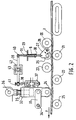
- FIG. 2 shows another embodiment of the device according to the invention.
- the product to be dressed 1 which is for example a concrete steel, is subjected to a dressing which is carried out by alternating bending around a series of rollers 20, 21, 22, 23, 24, 25 staggered.
- the straightening wire is drawn by known means to the left in the direction of arrow F.
- a feeler roller 26 mounted on a support 27 oscillating around a fixed axis 28 is arranged opposite the dresser roller 21.
- the feeler roller 26 is applied against the concrete steel 1 by a spring 8 whose upper end is supported on a fixed part 29 and whose lower end is supported on the shoulder 30 of a rod 31.
- the force of the spring 8 is sufficient to constantly apply the feeler roller 26 against the concrete steel 1 so that the position of the rod 31 makes it possible to determine its diameter in the dressing plane.
- the drawer 37 is controlled by a rod 38 provided with a roller at its end.
- a lever 39 is articulated at its end at 40 on the rod 31 and at its other end, it rests by means of the knurled screw 40 on the end of the lever 38 which, as has been said, is provided a roulette.
- the lever 39 is capable of tilting around a point 42 secured to a plate 43 which can be fixed in different positions parallel to the direction of the lever 39.
- the knurled screw 41 allows, for a given position of the feeler roller 26 which corresponds to the nominal diameter of the product to be straightened, to position the drawer 37 so as to obtain the basic setting of the pressure roller 24 which allows a straight output of the product to draw up 1.
- the feeler device is located upstream of the dresser roller 24 which is positioned according to the invention.
- the pressure drops in the hydraulic circuit are determined in such a way that the response time of the hydraulic cylinder 32 under the action of the distributor slide 37 corresponds to the time that it takes the product to be straightened 1 to cover the distance separating the feeler roller 26 from the dresser roller 24.
- FIG. 3 shows another embodiment of the invention which uses a blocker of the type described in French patent application No. 90 05569 of May 3, 1990.
- a blocker of this type shown in FIG. 3 comprises four plates A, B, C, D which are capable of being displaced in parallel with each other thanks to the fact that they are connected by connecting rods 44 to a lever 45 which is itself articulated on tray C. One of these trays is fixed.
- the dresser rollers 20, 21, 22, 23, 24, 25 are integral with arms 46 articulated on a plate and connected by a link 47 to the neighboring plate.
- the blocking rollers are fixed on the levers 46 at a quarter of the distance existing between the point of articulation of the levers 46 on their plate and their point of articulation on their link 47.
- the distance between the plates is modified by acting on the lever 45 by means of the threaded rod 48 which engages in a nut 49 which is free to rotate but which is kept axially in position, this nut being driven by a motor, for example hydraulic 50, by means of a gear train 51.
- any modification of the angular position of the lever 45 results in a displacement of the dressing rollers 20, 21, 22, 23, 24, 25 which remain equidistant from each other and which all approach or move apart in the same way of the axis of the product to be straightened 1.
- lever 52 articulated on the lever 46 which supports the roller 23.
- the lower end of this lever 52 carries a feeler roller 26 which is located in line with the dresser roller 23 against which it is pushed back by the action of the return spring 8 which joins the lever 52 to the plate D.
- the plate D supports a hydraulic slide 37 which is connected by a rod 53 at a point on the upper end of the lever 52.
- a flywheel 54 acting on two threads with opposite pitch makes it possible to modify the length of the rod 53 at will and to adapt the position of the feeler roller 26 so that for the nominal diameter of the product to be straightened and the corresponding position of the rollers dressers, the distributor drawer 37 is in a neutral position which does not modify the spacing between the plates A, B, C, D.
- the upper end of the lever 52 has a series of orifices 55 to each of which it is possible to connect the left end of the rod 53 so as to modify the amount of displacement of the hydraulic slide 37 for a given variation the diameter of the product to be straightened 1 as measured by the feeler roller 26.
- the hydraulic distributor 37 is used to supply the hydraulic motor 50 shown diagrammatically in the drawing.
- the feeler roller 26 detects an increase in the diameter of the product to be straightened 1
- the lever 52 pushes the rod 53 to the right which, thanks to the hydraulic slide 37 causes the hydraulic motor 50 to rotate and via the gear train 51 the rotation of the nut 49 which moves the threaded rod 48 and the end of the lever 45 to the left.
- the choice of one of the orifices 55 at the end of the lever 52 makes it possible to modify the amplification ratio of the movement of the hydraulic slide 37 as a function of the movements of the feeler roller 26.
- the response time of the control of the position of the dresser rollers to that of the feeler roller 26 is substantially equal to the time taken by the product to be dressed to go from the feeler roller 26 to the exit from the trainer.
- the motor 50, the gear train 51 and the nut 44 can be replaced by a hydraulic cylinder, for example.
- the invention can be applied to different types of devices which allow the movement of the dressing rollers to adapt them to the different diameters of the wire to be dressed.
- the servo-control of the position of the dressing roller (s) relative to the member detecting the diameter of the wire can be achieved by any mechanical, electrical or hydraulic means.
Landscapes
- Engineering & Computer Science (AREA)
- Mechanical Engineering (AREA)
- Finish Polishing, Edge Sharpening, And Grinding By Specific Grinding Devices (AREA)
- Wire Processing (AREA)
- Grinding Of Cylindrical And Plane Surfaces (AREA)
- Grinding-Machine Dressing And Accessory Apparatuses (AREA)
- Rehabilitation Tools (AREA)
Claims (15)
- Verfahren zur automatischen Regelung der Position wenigstens einer Richtrolle einer Rollenrichtmaschine im Hinblick auf das korrekte Richten eines länglichen Produktes (1), das Querschnittsvariationen aufweist, dadurch gekennzeichnet, daß man wahrend des Richtvorgangs den Durchmesser des zu richtenden Produkts (1) in einer zu den Achsen der Richtrollen (20, 21, 22, 23, 24, 25) rechtwinkligen Richtebene mißt (6, 7; 21, 26; 23, 26) und in Abhängigkeit von dem so bestimmten Durchmesser die Positionierung wenigstens einer der Richtrollen (24; 20, 21, 22, 23, 24, 25) vornimmt, wobei diese Positionierung dem korrekten Richten eines länglichen Produkts (1) entspricht, dessen Durchmesser in der Richtebene gleich dem gemessenen Durchmesser ist.
- Verfahren nach Anspruch 1, dadurch gekennzeichnet, daß man den Durchmesser des länglichen Produkts (1) stromaufwärts wenigstens einer Gruppe von Rollen mißt, die am Richten in der betrachteten Ebene beteiligt sind.
- Verfahren nach einem der vorstehenden Ansprüche, dadurch gekennzeichnet, daß man die Ansprechzeit der Einrichtung zum Positionieren der Rolle oder Rollen in Abhängigkeit vom Durchmesser des zu richtenden Produkts (1) bestimmt, derart, daß diese Ansprechzeit im wesentlichen der Dauer des Durchlaufs des zu richtenden Produkts (1) zwischen der Stelle, an der sein Durchmesser gemessen wird, bis zu der Stelle der am weitesten stromabwärts gelegenen Richtrolle entspricht, deren Position geregelt wird.
- Vorrichtung zur automatischen Regelung der Position wenigstens einer Richtrolle einer Rollenrichtmaschine zur Erzielung der Geradheit des zu richtenden Produkts (1) unabhängig der Durchmesserschwankungen des letzteren, welche Vorrichtung dadurch gekennzeichnet ist, daß sie in Kombination aufweist: eine Tasteinrichtung (6, 7; 21, 26; 23, 26) zur Bestimmung des Durchmessers des zu richtenden Produkts (1) in einer zu den Achsen der Rollen senkrechten Richtebene während des Richtvorgangs, eine Einrichtung (32; 44, 45) zum Modifizieren der Positionierung wenigstens einer der Richtrollen (24) und eine Regeleinrichtung (31, 39, 38, 37, 32; 52, 53, 37, 50, 51, 49, 45, 44), die es gestattet, die Position der Richtrolle oder -rollen in Abhängigkeit von dem mit der Tasteinrichtung (6, 7; 21, 26; 23, 26) gemessenen Durchmesser des zu richtenden Produkts zu modifizieren.
- Vorrichtung nach Anspruch 4, dadurch gekennzeichnet, daß die Tasteinrichtung stromaufwärts der Richtmaschine angeordnet ist.
- Vorrichtung nach Anspruch 4, dadurch gekennzeichnet, daß die Tasteinrichtung (6, 7; 21, 26; 23, 26) zwischen den Richtrollen (24; 20-25), jedoch stromaufwärts wenigstens einer der Richtrollen (24; 20-25) angeordnet ist, deren Position automatisch geregelt wird.
- Vorrichtung nach einem der Ansprüche 4 bis 6, dadurch gekennzeichnet, daß das Tastorgan durch zwei Rollen (6, 7) gebildet wird, die von beiden Selten an dem zu richtenden Produkt (1) anliegen.
- Vorrichtung nach einem der Ansprüche 4 bis 6, dadurch gekennzeichnet, daß die Tastrolle (26) gegenüberliegend zu einer Richtrolle (21, 23) an dem zu richtenden Produkt (1) anliegt.
- Vorrichtung nach Anspruch 7 oder 8, dadurch gekennzeichnet, daß die Tastrolle (7; 26) einen offenen V-förmigen Querschnitt mit einem Winkel von etwa 100 bis 120° hat.
- Vorrichtung nach einem der vorstehenden Ansprüche, dadurch gekennzeichnet, daß sie die Einstellung der Richtmaschine für ein zu richtendes Produkt (1) mit einem gegebenen Durchmesser gestattet, indem sie auf die Einstellung der Regeleinrichtung einwirkt, die die Tasteinrichtung mit der (den) Richtrolle(n) zu verbindet, deren Position modifizierbar ist.
- Vorrichtung nach einem der Ansprüche 4 bis 10, dadurch gekennzeichnet, daß sie es gestattet, die Änderungen der Voreinstellposition der regelbaren Richtrolle oder -rollen in Abhängigkeit von der Änderung des Durchmessers des zu richtenden Produkts (1) zu bestimmen, indem sie auf die Einstellung der Regeleinrichtung einwirkt.
- Vorrichtung nach einem der Ansprüche 4 bis 11, dadurch gekennzeichnet, daß die Ansprechzeit der Positionierung der Richtrolle oder -rollen (24; 20-25) auf die Position das Tastorgans (7; 26) im wesentlichen gleich der Zeit ist, die das zu richtende Produkt (1) benötigt, um die Entfernung zwischen der Tasteinrichtung (6, 7; 21, 26; 23, 26) und der am weitesten stromabwärts gelegenen Rolle zurückzulegen, deren Position geregelt wird.
- Vorrichtung nach einem der Ansprüche 4 bis 12, dadurch gekennzeichnet, daß die Rolle oder Rollen, deren Position in Abhängigkeit von der Position des Durchmessers des zu richtenden Produkts modifiziert wird, zu den letzten drei Rollen gehören, die auf der stromabwärtigen Seite der Richtmaschine angeordnet sind.
- Vorrichtung nach einem der Ansprüche 4 bis 12, dadurch gekennzeichnet, daß sämtliche Rollen (20-25) der Richtmaschine in Abhängigkeit vom Durchmesser des zu richtenden Produkts positioniert werden.
- Vorrichtung nach einem der Ansprüche 4 bis 14, dadurch gekennzeichnet, daß die Regeleinrichtung zwischen dem Taster, der den Durchmesser des zu richtenden Produkts bestimmt, und der oder den verstellbaren Richtrollen eine hydraulische Einrichtung (37) aufweist.
Applications Claiming Priority (2)
| Application Number | Priority Date | Filing Date | Title |
|---|---|---|---|
| FR9006371 | 1990-05-22 | ||
| FR9006371A FR2662379B1 (fr) | 1990-05-22 | 1990-05-22 | Procede et dispositif pour le reglage automatique des dresseurs a galets. |
Publications (2)
| Publication Number | Publication Date |
|---|---|
| EP0459869A1 EP0459869A1 (de) | 1991-12-04 |
| EP0459869B1 true EP0459869B1 (de) | 1995-01-11 |
Family
ID=9396841
Family Applications (1)
| Application Number | Title | Priority Date | Filing Date |
|---|---|---|---|
| EP91401318A Expired - Lifetime EP0459869B1 (de) | 1990-05-22 | 1991-05-22 | Verfahren und Vorrichtung zur automatischen Regelung von Richtwalzen |
Country Status (4)
| Country | Link |
|---|---|
| EP (1) | EP0459869B1 (de) |
| AT (1) | ATE116879T1 (de) |
| DE (1) | DE69106591D1 (de) |
| FR (1) | FR2662379B1 (de) |
Cited By (1)
| Publication number | Priority date | Publication date | Assignee | Title |
|---|---|---|---|---|
| CN105537463A (zh) * | 2016-01-25 | 2016-05-04 | 宁波新州焊接设备有限公司 | 一种钢筋矫直滚筒装置 |
Families Citing this family (13)
| Publication number | Priority date | Publication date | Assignee | Title |
|---|---|---|---|---|
| DE4325492A1 (de) * | 1993-07-29 | 1995-02-02 | Meyer Roth Pastor Maschf | Richtmaschine für strang- oder bandförmiges Richtgut |
| CN100374226C (zh) * | 2003-09-25 | 2008-03-12 | 张光伟 | 热轧带肋钢筋矫直导向辊 |
| DE102006028102A1 (de) * | 2006-06-19 | 2007-12-20 | Siemens Ag | Abhaspeleinrichtung |
| IT1398481B1 (it) | 2010-02-17 | 2013-03-01 | Schnell Spa | Metodo e apparecchiatura per raddrizzare tondini di ferro e simili |
| IT1401411B1 (it) | 2010-08-04 | 2013-07-26 | Schnell Spa | Metodo e apparecchiatura per la correzione delle sollecitazioni di torsione in tondini metallici. |
| CN103658242A (zh) * | 2012-09-25 | 2014-03-26 | 昆山尚达智机械有限公司 | 自动校直机 |
| ITUA20162848A1 (it) | 2016-04-22 | 2017-10-22 | Schnell Spa | Metodo per regolare automaticamente la raddrizzatura di elementi metallici di foggia allungata e apparecchiatura per raddrizzare gli stessi elementi |
| CN108637133B (zh) * | 2018-06-14 | 2023-12-05 | 建科机械(天津)股份有限公司 | 一种矫直装置 |
| CN109014768A (zh) * | 2018-08-01 | 2018-12-18 | 成都飞机工业(集团)有限责任公司 | 针对长度方向不等厚结构零件的校正装置及其校正方法 |
| CN112912187B (zh) * | 2018-10-31 | 2023-07-28 | 施洛伊尼格股份公司 | 电缆加工机的矫直装置和用于操作矫直机构的方法 |
| JP6785399B1 (ja) * | 2019-10-11 | 2020-11-18 | 新明和工業株式会社 | 電線矯正装置、それを備えた電線処理装置、および電線矯正方法 |
| CN112475118A (zh) * | 2020-11-27 | 2021-03-12 | 安徽迪那通电线有限公司 | 一种电线生产用自动矫直机 |
| CN120715074B (zh) * | 2025-08-28 | 2025-12-12 | 蓬莱金馨铜业有限公司 | 一种铜管加工用矫直装置及其矫直方法 |
Family Cites Families (2)
| Publication number | Priority date | Publication date | Assignee | Title |
|---|---|---|---|---|
| DE1752406A1 (de) * | 1968-05-21 | 1971-09-02 | Masch Und Bohrgeraete Fabrik | Verfahren und Vorrichtung zum Richten von Gut auf einer Rollenrichtmaschine |
| US4719781A (en) * | 1986-08-07 | 1988-01-19 | Jean Cloup | Device for straightening metal wires by means of a plurality of rollers |
-
1990
- 1990-05-22 FR FR9006371A patent/FR2662379B1/fr not_active Expired - Lifetime
-
1991
- 1991-05-22 DE DE69106591T patent/DE69106591D1/de not_active Expired - Lifetime
- 1991-05-22 EP EP91401318A patent/EP0459869B1/de not_active Expired - Lifetime
- 1991-05-22 AT AT91401318T patent/ATE116879T1/de active
Cited By (1)
| Publication number | Priority date | Publication date | Assignee | Title |
|---|---|---|---|---|
| CN105537463A (zh) * | 2016-01-25 | 2016-05-04 | 宁波新州焊接设备有限公司 | 一种钢筋矫直滚筒装置 |
Also Published As
| Publication number | Publication date |
|---|---|
| FR2662379B1 (fr) | 1992-09-04 |
| FR2662379A1 (fr) | 1991-11-29 |
| DE69106591D1 (de) | 1995-02-23 |
| ATE116879T1 (de) | 1995-01-15 |
| EP0459869A1 (de) | 1991-12-04 |
Similar Documents
| Publication | Publication Date | Title |
|---|---|---|
| EP0459869B1 (de) | Verfahren und Vorrichtung zur automatischen Regelung von Richtwalzen | |
| EP2177292B1 (de) | Vorrichtung zum Richten und Zuführen von einem halbstarren Materialstreifen in eine Maschine | |
| FR2502990A1 (fr) | Laminoir a plusieurs niveaux avec mecanisme de reglage de l'aplatissement du produit lamine | |
| EP0298852A2 (de) | Verfahren und Vorrichtung zum Richten eines metallischen Bandes | |
| EP0649686A1 (de) | Walzwerk mit axial verschiebaren Walzen | |
| EP1685934A1 (de) | Drahtsägevorrichtung und Verfahren | |
| EP1552892B1 (de) | Vorrichtung zum Richten von Metallbändern | |
| BE1003884A5 (fr) | Procede de tuftage et dispositif pour la mise en oeuvre de ce procede. | |
| FR2550773A1 (fr) | Procede et dispositif pour separer des groupes d'objets en forme de disques d'une pile qui arrive en un courant | |
| EP0473739B1 (de) | Drahtrichtvorrichtung | |
| FR2469965A2 (fr) | Procede et dispositif de fabrication de ressorts helicoidaux | |
| FR2550486A1 (fr) | Machine de coupe a disques a commande numerique et procede de reglage de ses ensembles de coupe | |
| FR2600919A1 (fr) | Procede et dispositif pour la retouche due a l'usure des cylindres d'un laminoir, sur la ligne de laminage | |
| EP0506575A1 (de) | Universale Richt- und Biegemaschine für Bewehrungen aus Betonstahl | |
| EP0225198A1 (de) | Vorrichtung zum Streckrichten eines metallischen Bandes | |
| FR2473027A1 (fr) | Dispositif pour l'enroulement helicoidal des bandes obtenues en coupant un feuillard large dans le sens longitudinal | |
| FR2473383A1 (fr) | Machine pour faire tourner coaxialement a elle-meme une piece de revolution, notamment a balourd | |
| FR2770749A1 (fr) | Faconneuse de patons | |
| EP0527205B1 (de) | Rollenrichtmaschine, insbesonders für betoneisenstäbe | |
| EP1086768B1 (de) | Streifenschere mit kompensierter Durchbiegung | |
| FR2458327A1 (fr) | Agrafeuse de tubes | |
| FR2575682A1 (fr) | Dispositif pour le dressage de pieces a symetrie de revolution deformables a froid, en particulier des axes, des arbres, des boulons et des pieces analogues | |
| FR2484981A1 (fr) | Dispositif d'introduction et de sortie reglees d'un fil dans et d'un appareil de traitement | |
| FR2716395A1 (fr) | Dispositif de laminage circulaire de bagues notamment de roulements. | |
| FR2708882A1 (fr) | Procédé et dispositif de dressage de fils metalliques pour machine à cambrer. |
Legal Events
| Date | Code | Title | Description |
|---|---|---|---|
| PUAI | Public reference made under article 153(3) epc to a published international application that has entered the european phase |
Free format text: ORIGINAL CODE: 0009012 |
|
| AK | Designated contracting states |
Kind code of ref document: A1 Designated state(s): AT BE CH DE DK ES FR GB GR IT LI NL |
|
| 17P | Request for examination filed |
Effective date: 19920525 |
|
| 17Q | First examination report despatched |
Effective date: 19930617 |
|
| GRAA | (expected) grant |
Free format text: ORIGINAL CODE: 0009210 |
|
| AK | Designated contracting states |
Kind code of ref document: B1 Designated state(s): AT BE CH DE DK ES FR GB GR IT LI NL |
|
| PG25 | Lapsed in a contracting state [announced via postgrant information from national office to epo] |
Ref country code: IT Free format text: LAPSE BECAUSE OF FAILURE TO SUBMIT A TRANSLATION OF THE DESCRIPTION OR TO PAY THE FEE WITHIN THE PRESCRIBED TIME-LIMIT;WARNING: LAPSES OF ITALIAN PATENTS WITH EFFECTIVE DATE BEFORE 2007 MAY HAVE OCCURRED AT ANY TIME BEFORE 2007. THE CORRECT EFFECTIVE DATE MAY BE DIFFERENT FROM THE ONE RECORDED. Effective date: 19950111 Ref country code: GB Effective date: 19950111 Ref country code: GR Free format text: LAPSE BECAUSE OF FAILURE TO SUBMIT A TRANSLATION OF THE DESCRIPTION OR TO PAY THE FEE WITHIN THE PRESCRIBED TIME-LIMIT Effective date: 19950111 Ref country code: ES Free format text: THE PATENT HAS BEEN ANNULLED BY A DECISION OF A NATIONAL AUTHORITY Effective date: 19950111 Ref country code: DK Effective date: 19950111 Ref country code: AT Effective date: 19950111 Ref country code: NL Effective date: 19950111 |
|
| REF | Corresponds to: |
Ref document number: 116879 Country of ref document: AT Date of ref document: 19950115 Kind code of ref document: T |
|
| REF | Corresponds to: |
Ref document number: 69106591 Country of ref document: DE Date of ref document: 19950223 |
|
| PG25 | Lapsed in a contracting state [announced via postgrant information from national office to epo] |
Ref country code: DE Effective date: 19950412 |
|
| PG25 | Lapsed in a contracting state [announced via postgrant information from national office to epo] |
Ref country code: LI Effective date: 19950531 Ref country code: CH Effective date: 19950531 Ref country code: BE Effective date: 19950531 |
|
| NLV1 | Nl: lapsed or annulled due to failure to fulfill the requirements of art. 29p and 29m of the patents act | ||
| GBV | Gb: ep patent (uk) treated as always having been void in accordance with gb section 77(7)/1977 [no translation filed] |
Effective date: 19950111 |
|
| PLBE | No opposition filed within time limit |
Free format text: ORIGINAL CODE: 0009261 |
|
| STAA | Information on the status of an ep patent application or granted ep patent |
Free format text: STATUS: NO OPPOSITION FILED WITHIN TIME LIMIT |
|
| BERE | Be: lapsed |
Owner name: CARRERE NOEL Effective date: 19950531 |
|
| 26N | No opposition filed | ||
| REG | Reference to a national code |
Ref country code: CH Ref legal event code: PL |
|
| PGFP | Annual fee paid to national office [announced via postgrant information from national office to epo] |
Ref country code: FR Payment date: 19961202 Year of fee payment: 6 |
|
| PG25 | Lapsed in a contracting state [announced via postgrant information from national office to epo] |
Ref country code: FR Free format text: LAPSE BECAUSE OF NON-PAYMENT OF DUE FEES Effective date: 19980130 |
|
| REG | Reference to a national code |
Ref country code: FR Ref legal event code: ST |