EP0459635A1 - Lichthärtungsformungsaparatur - Google Patents
Lichthärtungsformungsaparatur Download PDFInfo
- Publication number
- EP0459635A1 EP0459635A1 EP91303956A EP91303956A EP0459635A1 EP 0459635 A1 EP0459635 A1 EP 0459635A1 EP 91303956 A EP91303956 A EP 91303956A EP 91303956 A EP91303956 A EP 91303956A EP 0459635 A1 EP0459635 A1 EP 0459635A1
- Authority
- EP
- European Patent Office
- Prior art keywords
- region
- solidified
- contour
- data
- exposure
- Prior art date
- Legal status (The legal status is an assumption and is not a legal conclusion. Google has not performed a legal analysis and makes no representation as to the accuracy of the status listed.)
- Granted
Links
Images


Classifications
-
- B—PERFORMING OPERATIONS; TRANSPORTING
- B29—WORKING OF PLASTICS; WORKING OF SUBSTANCES IN A PLASTIC STATE IN GENERAL
- B29C—SHAPING OR JOINING OF PLASTICS; SHAPING OF MATERIAL IN A PLASTIC STATE, NOT OTHERWISE PROVIDED FOR; AFTER-TREATMENT OF THE SHAPED PRODUCTS, e.g. REPAIRING
- B29C64/00—Additive manufacturing, i.e. manufacturing of three-dimensional [3D] objects by additive deposition, additive agglomeration or additive layering, e.g. by 3D printing, stereolithography or selective laser sintering
- B29C64/40—Structures for supporting 3D objects during manufacture and intended to be sacrificed after completion thereof
-
- B—PERFORMING OPERATIONS; TRANSPORTING
- B29—WORKING OF PLASTICS; WORKING OF SUBSTANCES IN A PLASTIC STATE IN GENERAL
- B29K—INDEXING SCHEME ASSOCIATED WITH SUBCLASSES B29B, B29C OR B29D, RELATING TO MOULDING MATERIALS OR TO MATERIALS FOR MOULDS, REINFORCEMENTS, FILLERS OR PREFORMED PARTS, e.g. INSERTS
- B29K2995/00—Properties of moulding materials, reinforcements, fillers, preformed parts or moulds
- B29K2995/0037—Other properties
- B29K2995/0072—Roughness, e.g. anti-slip
- B29K2995/0073—Roughness, e.g. anti-slip smooth
Definitions
- the present invention relates to an improvement in a photo-solidification modeling device for forming a solidified image having a desired model shape by exposing to light a liquid capable of being solidified in receipt of the light in a region corresponding to the desired model shape.
- a photo-solidification modeling device for forming a solidified image having a desired model shape by exposing to light a liquid capable of being solidified in receipt of the light in a region corresponding to the desired model shape.
- the distortion of the desired model shape during the modeling process can be considerably prevented.
- an operator must decide a forming position of the supporting rib and then set an exposure region corresponding to this position, thus rendering the operation troublesome.
- a photo-solidification modeling device for forming a solidified image having a desired model shape by exposing to light a liquid capable of being solidified in receipt of the light in a region corresponding to the desired model shape, the device comprising means for providing data indicative of a regularly spaced region in addition to data indicative of said region corresponding to said desired model shape and setting an exposure region according to said additional data.
- a solidified structure that is, a supporting rib is arranged at regular intervals in a given space, and a model is formed in the given space, thereby preventing the distortion of the model during the modeling process. Further, an operator need not consider and input a position or the like of the supporting rib. Further, a shape such as an overhung shape difficult to model in the conventional method can be easily modeled.
- the regular exposure pattern for forming the supporting rib is selectable from plural kinds of predetermined patterns.
- various patterns of arrangement of the supporting rib can be set, thereby obtaining various shapes of the model.
- a spatial region for forming the supporting rib therein can be set. In this case, formation of undue supporting rib is prevented.
- the above-mentioned spatial region is set in relation to the model. That is, it is preferable that the spatial region is selectable from a whole region outside the desired model shape, a whole region below the desired model shape, and a whole region inside and outside the desired model shape. In this case, the supporting rib can be easily removed after the modeling is terminated.
- Figs. 1A to 1C show an example of a system construction of the photo-solidification modeling device improved in utilizing the present invention.
- Figs. 2A and 2B show an essential operation of the system shown in Figs. 1A to 1C.
- 1-46 denotes a closed container for storing a liquid having a property of solidification when it is exposed to light.
- the container 1-46 has a transparent upper surface.
- the liquid is preferably a photosensitive resin. More preferably, the liquid may be a mixture of one, two or more of deformed polyurethane methacrylate, oligoester acrylate, urethane acrylate, epoxy acrylate, photosensitive polyimide, and aminoalkyd.
- a sensitizer, opaque substance, etc. may be mixed in the liquid, so as to adjust a photoabsorption characteristic or the like.
- a pigment, ceramics powder, filler, metal powder, etc. may be mixed in the liquid, so as to adjust a color, strength, distortion, modeling accuracy, etc. of a model.
- a base 1-45 is vertically (Z direction) movably provided below a liquid surface 1-43 in the container 1-46.
- a light source (preferably, a laser) 1-38 is provided above the container 1-46. Light from the light source 1-38 is introduced through a filter 1-39 having both a light shutter function and an exposure quantity adjusting function to an optical fiber 1-40. A tip 1-40a of the optical fiber 1-40 is movable by an XY driving mechanism 1-41 in two orthogonal directions (XY directions).
- a brush 1-42 capable of sweeping the liquid surface 1-43 is movable in the Y direction shown.
- a solidification modeling part of the prevent device is formed by the above construction, and it is controlled in the following manner by a system to be hereinafter described.
- the base 1-45 is lowered from the liquid surface 1-43 by a unit thickness ⁇ Z of a model.
- the tip 1-40a of the optical fiber 1-40 is scanned in the XY direction in a region corresponding to a lowermost section of a desired model shape.
- the liquid in the region exposed to light is solidified to form a section solidified image 1-44a corresponding to the lowermost section of the desired model shape on the base 1-45.
- the base 1-45 is further lowered by ⁇ Z.
- the lowermost section solidified image 1-44a is also lowered together with the base 1-45, and simultaneously the peripheral liquid is allowed to flow onto the lowermost section solidified image 1-44a.
- the liquid has a high viscosity
- the liquid is hard to flow onto the solidified image 1-44a if the base 1-45 is merely lowered by ⁇ Z.
- the brush 1-42 is operated to sweep the liquid surface 1-43, thereby positively introducing the liquid onto the solidified image 1-44a.
- the tip 1-40a of the optical fiber 1-40 is scanned in the XY directions to form a subsequent section solidified image 1-44b on the solidified image 1-44a.
- Reference number 1-28 in Fig. 1C denotes an external system connected to the present system by way of on-line or off-line connection.
- Such an external system may be selected from a three-dimensional CAD system, three-dimensional measuring instrument, continuous tomographic system, etc. These are merely exemplary, and it is sufficient for the external system to have data relating to a three-dimensional shape of the model.
- the form of data included in the external system 1-28 is of a triangular patch type
- the data is directly stored into a triangular patch type desired model shape data storing means 1-7 in the present system.
- the data included in the external system 1-28 is of any types other than the triangular patch type
- the data is once converted into the triangular patch type by a triangular patch type converting means 1-31 in the present system, and is then stored into the storing means 1-7.
- FIG. 3 A schematic construction of the triangular patch type is shown in Figs. 3 and 4.
- the three-dimensional shape is defined as a set of many triangular patches P I , P J , P K , etc. in the triangular patch type.
- a part of the set of these triangular patches is simply shown for the purpose of legibility of illustration.
- Each triangular patch is defined in position and shape by XYZ coordinates of three vertexes.
- the patch P I is given XYZ coordinates of three vertexes I1, I2 and I3.
- the three-dimensional shape data of the triangular patch type has a structure as shown in Fig. 4.
- the data having the structure shown in Fig. 4 and stored into the storing means 1-7 is editable by a data editing means 1-8 shown in Fig. 1B (see step 2-8 in Fig. 2A).
- the desired mode shape data can be expanded, contracted, rotated or corrected.
- a support data for supporting the desired model shape may be added.
- a new three-dimensional shape data may be created by using this correcting function.
- a perspective view of the edited desired model shape sliced with the unit thickness is displayed on a two-dimensional display 1-32 (see step 2-50 of simulation and step 2-32 of displaying in Fig. 2A). Then, the operator confirms whether or not the modeling is to be started under the above condition, and if NO in step 2-51, the operator resets the condition (see the loop from step 2-51). If the condition is satisfied, the following processing is executed in the present system.
- a beam scanning speed computing means 1-9 shown in Fig. 1B computes an optimum scanning speed for solidifying the unit thickness set by the means 1-1 with the beam diameter set by the means 1-2.
- a horizontal plane extracting means 1-10 is started in step 2-10 to extract a horizontal plane from the desired model shape.
- the unit thickness ⁇ Z set by the means 1-1 is employed, and as shown in Fig. 5B, the triangular patches each having the three vertexes all contained within the height range of ⁇ Z are searched to compute an outside contour 5-1 of the set of these triangular patches.
- Fig. 5B shows a virtual side view of these triangular patches, in which the three vertexes of each patch P I reside inside the width of the unit thickness ⁇ Z, and at least one of the three vertexes of each patch P O reside outside the width of the unit thickness ⁇ Z.
- the contour 5-1 of the horizontal plane is extracted and computed from the outermost line of the set of the patches P I .
- Fig. 5A is a virtual view of horizontal planes 5-1a and 5-1b extracted from the,triangular patch data shown in Fig. 3.
- the present system executes computation of a contour by using a contour computing means 1-11 shown in Fig. 1B (see step 2-11 in Fig. 2A).
- Fig. 6 is a schematic illustration of the contour computing, in which each unhorizontal triangular patch (patches S and T being exemplarily shown in Fig. 6) intersects a horizontal plane Z sliced with the unit thickness ⁇ Z, and two intersections between each patch and the plane Z are computed.
- the two intersections between the patch S and the plane Z are denoted by (X L , Y L )S and (X R , Y R )S, while the two intersections between the patch T and the plane Z are denoted by (X L , Y L )T and (X R , Y R )T.
- a common intersection resides on the adjacent line. That is, the intersection (X R , Y R )S is equal to the intersection (X L , Y L )T.
- the triangular patches in some section are not continuous to define a gap G. That is, the extracted contours 7-1 and 7-2 do not form a closed curve. In this case, the nearest intersections are searched, and they are connected together to thereby obtain a closed curve. As shown in Fig. 7, the contours thus computed are classified into a group for forming a desired model shape inside the contour (e.g., 7-1) and a group for forming the desired model shape outside the contour (e.g., 7-2).
- Such classification is effected by searching the contours along a search line 7-4 from the left side, for example, and giving an inside indicating flag for the contour 7-1 first intersecting the search line 7-4 and an outside indicating flag for the contour 7-2 secondly intersecting the search line 7-4.
- the present system includes a beam corresponding solidifying region data computing and storing means 1-12.
- the means 1-12 computes and stores a sectional shape of a region to be solidified when the beam having the beam diameter set by the means 1-2 is scanned at the speed computed by the means 1-9. That is, as shown in Fig. 8C, the means 1-12 computes and stores a sectional shape F2 of a region F1 to be solidified when a light beam 8-12 is scanned as shown by an arrow 8-10.
- a three-dimensional offset quantity computing means 1-13 shown in Fig. 1B computes a three-dimensional offset quantity for the horizontal line data extracted by the means 1-10 and the contour data computed by the means 1-11 by using a solidifying region data computed by the means 1-12.
- FIG. 8A which is a plan view of the liquid surface
- 8-2 denotes an exposure region of the light beam.
- a contour 8-1 (computed by the means 1-11) as shown by an arrow 8-4
- a contour 8-5 of a region to be solidified is undesirably formed outside the contour 8-1.
- Fig. 8B is a stereoscopic view of Fig. 8A. As shown in Fig. 8B, in the case that the center of the light beam resides on the contour of the model, regions 8-5a, 8-5b, 8-5c, etc. are solidified, and the contour of an actual solidified region to be formed by continuously connecting outermost surfaces of the regions 8-5a, 8-5b, 8-5c, etc. does not coincide with the contour 8-1.
- the conventional photo-solidification modeling device practically used at present is so designed as to scan the center of the light beam along a line offset inside of the contour by a radius of the beam as shown in a left lower area of Fig. 8A.
- a contour of the solidified region becomes coincident with the contour 8-1 as far as viewed in plan.
- a problem remains from a stereoscopic standpoint.
- 8-8 denotes a region to be solidified by the light beam offset inside by the radius d. Since the desired model shape is gradually narrowed to the lowermost surface, it is understood that a hatched portion of the region 8-8 is excessively solidified. Accordingly, a contour 8-9 of an actual model shape becomes outside the contour 8-1 of the desired model shape.
- Figs. 9A to 9F show a method of three-dimensionally offsetting the exposure region of the light beam, so as to eliminate the above problem.
- Fig. 9A shows a three-dimensional coordinate system wherein the origin coincides with one of the intersections between the triangular patch and the horizontal plane Z shown in Fig. 6.
- the origin of the coordinate system shown in Fig. 9A coincides with the intersection (X R , Y R )S or (X L , Y L )T.
- F2A to F2D denote a common three-dimensional shape to be formed by rotating the sectional shape F2 shown in Fig. 8C about the center of the beam
- N denotes a unit normal vector at the origin, i.e., the intersection (X R , Y R )S or (X L , Y L )T.
- the unit normal vector N is calculated as a vector sum of unit normal vectors N S or N T with respect to the adjacent patches shown in Fig. 6.
- Direction of each of the unit normal vectors N S and N T is computed from the vertex coordinates of each patch, and the sense of each vector is defined with reference to the inside and outside indicating flags previously mentioned in relation to the search line 7-4 in Fig. 7.
- the sense of each vector is defined such that each vector is oriented from the inside to the outside of the desired model shape.
- the unit normal vector N thus computed has components n x , n y and n z .
- n R denotes a vector having the components n x and n y in the XY plane, and an R axis is given in the direction of the vector n R .
- Fig. 9B shows an RZ plane given in Fig. 9A.
- F2A denotes a solidified region to be obtained when the beam center coincides with the intersection (i.e., the origin in this case). It is apparent that a large proportion of the solidified region F2A is formed outside the contour 8-1.
- F2B denotes a solidified region to be obtained when the beam center is offset inside the contour 8-1 along the R axis by the radius d. It is understood that a hatched portion of the solidified region F2B is formed outside the contour 8-1.
- F2C denotes a solidified region to be obtained when the beam center C1 is offset inside the contour 8-1 so that a three-dimensional contour 9-2c of the solidified region F2C passes the intersection (the origin) and that a normal vector for the contour 9-2c coincides with the normal vector N for the contour 8-1 at the origin.
- the solidified region F2C is offset inside the contour 8-1 so that the contour 9-2c of the solidified region F2C contacts the contour 8-1 at the origin.
- F2D denotes a solidified region to be obtained by moving the solidified region F2C in a direction perpendicular to the normal vector N in the RZ plane so that a Z coordinate of the beam center CO becomes zero.
- the contour of the three-dimensional solidified region can be made substantially coincident with the contour of the desired model shape without changing the height of the beam center.
- the means 1-13 computes an offset quantity of the beam center.
- the latter method is suitably adopted.
- the former method may be adopted to three-dimensionally offset the beam center.
- Fig. 9C shows a vertical section of a laminated solidified region in the case of offsetting the beam center by the radius d.
- Fig. 9D shows a vertical section of a laminated solidified region in the case of offsetting the beam center by the distances X0 and Y0 as mentioned above.
- a contour 9-12 of the laminated solidified region according to the offsetting method of the present invention as shown in Fig. 9D is made substantially coincident with a contour 9-1 of the desired model shape.
- Fig. 9E shows the case where a contour of each exposure region is made coincident with the contour 9-1 of the desired model shape. As apparent from Fig. 9E, hatched portions 9-6a, 9-6b, 9-6c, 9-6d, etc. of the exposure regions are excessively solidified to come outside of the contour 9-1.
- Fig. 9F shows the improvement of Fig. 9E, wherein contours 9-11a, 9-11b, 9-11c, 9-11d, etc. of the solidified regions are offset inside by the amount of R0 so as to contact the contour 9-1.
- a contour 9-12 of the solidified image can be made substantially coincident with the contour 9-1 of the desired model shape.
- a contour corresponding exposure region data computing and storing means 1-14 computes and stores a data relating to a scanning position of the beam center for offsetting the exposure region by the computed offset quantity and solidifying the exposure region corresponding to the horizontal line extracted by the means 1-10 or the contour computed by the means 1-11.
- the present system further includes a means 1-3 for setting an exposure mode for an inside region 7-5 surrounded by the contours 7-1 and 7-2 or an inside region 7-6 surrounded by the contour 7-3 as shown in Fig. 7, for instance (see step 2-3 in Fig. 2A).
- This exposure mode is classified into a non-exposure mode, whole region exposure mode and spaced exposure mode.
- a hollow model solidified at the contour only is fabricated as shown in Fig. 10F.
- an outer surface 10-2a shown in Fig. 10F corresponding to a contour 10-2 show-n in Fig. 10A is solidified
- an inner surface 10-3a shown in Fig. 10F corresponding to a contour 10-3 shown in Fig. 10A is also solidified.
- an inside region between the contours 10-2 and 10-3 is not solidified to define a hollow portion 10-8, thus fabricating a hollow model.
- This mode is effective in the case where the model shape only is important, and the strength is not so demanded. As the exposure region is small, a modeling time can be shortened.
- the inside region between the contours 10-2 and 10-3 is wholly solidified to fabricate a solid model as shown in Fig. 10B.
- This mode is suitable in the case where the strength of the model is demanded.
- the operator can select one of a normal cross mode (Fig. 10C), alternate cross mode (Figs. 10D1 and 10D2), and stripe mode (Fig. 10E).
- a normal cross mode Fig. 10C
- alternate cross mode Figs. 10D1 and 10D2
- stripe mode Fig. 10E
- the inside region is spacedly exposed in one direction.
- the inside region is spacedly exposed in two different directions in the same section.
- the alternate cross mode shown in Figs. 10D1 and 10D2 the inside region is spacedly exposed by alternating the scanning direction in the stripe mode in every section.
- the operator can set by using a means 1-3c1 a desired pattern (i.e., normal cross, alternate cross or stripe), pitch and exposure width.
- the exposure width can be set to be different from the beam diameter set by the means 1-2.
- a honeycomb structure is additionally formed in the hollow model to fabricate a honeycomb model.
- an offset means 1-17 is started.
- the offset means 1-17 computes an offset quantity shown in Figs. 10G and 10H.
- 10-14 denotes a light beam for exposing the contour.
- the light beam 10-14 is scanned along an arrow 10-16 with the beam center being offset inside the contour to a position 10-15.
- 10-10 denotes a light beam for exposing the inside region.
- a contour corresponding solidified region 10-14a is not sufficiently connected to an inside region corresponding solidified region 10-10a as shown in Fig. 10H(1), with the result that a sufficient supporting effect by the honeycomb structure cannot be obtained.
- the offset means 1-17 computes an optimum offset quantity of the light beam 10-10 in such a manner that the scanning of the light beam 10-10 is stopped at a position where the leading end 10-12a of the light beam 10-10 contacts the beam center 10-15 of the light beam 10-14, that is, the beam center 10-12 of the light beam 10-10 is offset inside the circumference of the light beam 10-14 by a radius of the light beam 10-10 (see Fig. 10H(2)).
- the exposure region in the inside region is computed and stored by an inside region corresponding exposure region data computing and storing means 1-18 according to the information set by the means 1-3 and the offset quantity computed by the means 1-17 (see step 2-18 in Fig. 2A).
- Such an overlapping range between the contour corresponding exposure region and the inside region corresponding exposure region may be appropriately set by the operator, within the range between Figs. 10H(1) and Fig. 10H(3).
- 11-9 denotes a plurality of legs formed on the base 1-45.
- a desired model shape 11-1 is formed on the legs 11-9. If the solidified image of the model is directly laminated on the base 1-45 without the legs 11-9, the solidified image is broken or distorted when removed from the base 1-45. So, the legs 11-9 are provided for the purpose of prevention of this problem.
- the legs 11-9 are formed in spatial ranges 11-4a and 11-4b corresponding to lowermost sections 11-3a and 11-3b searched by using a means 1-19.
- the legs 11-9 are also formed in a frame setting space 11-2 to be hereinafter described.
- the leg data includes data of a leg height, pitch, line width and pattern (stripe, normal cross or alternate cross). These data are set by using means 1-4a and 1-4b.
- the leg data further includes data of whether an outline is present or absent. This data is set by using a means 1-4c.
- the leg height means a height of each leg to be solidified prior to modeling of the desired model shape.
- the pattern, pitch and line width are the same as those previously mentioned.
- the outline means an outline to be formed along a boundary of a leg forming region.
- a peripheral leg 11-7 (see Fig. 11D) or a peripheral leg 11-8 (see Fig. 11E) is formed along the boundary of the leg forming region 11-4a.
- Figs. 11B and 11D show the case where the stripe mode is set to form stripe legs 11-5.
- Figs. 11C and 11E show the case where the normal cross mode is set to form normal cross legs 11-6.
- a leg corresponding exposure region data computing and storing means 1-20 computes and stores an exposure region data for the formation of the legs as referring to the leg data set above, the information of the lowermost section, and data relating to a frame setting space which will be hereinafter described (see step 2-20 in Fig. 2B).
- the operator can set the frame setting space by using a means 1-5 in the present system.
- the operator can select whether a whole space is to be set by using a means 1-5a or a specific space is to be set by using a means 1-5b.
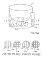
- a maximum contour range computing means 1-21 is started to compute a rectangular parallelepiped 12-2 entirely covering a desired model shape 12-1 as shown in Fig. 12A. Then, a frame corresponding exposure region data computing and storing means 1-22 computes and stores an exposure region data for forming a frame to be solidified at four side walls of the rectangular parallelepiped 12-2.
- such a specific space is specified by coordinate data (X1, Y1) and (X2, Y2) of a diagonal as shown in Fig. 12A, and the means 1-22 computes and stores an exposure region data for forming a frame to be solidified at four side walls of a rectangular parallelepiped 12-3 having a rectangular bottom surface defined by the above diagonal.
- the frame functions as a model shape supporting means in cooperation with a support to be formed inside the frame as will be hereinafter described.
- the operator can also set a support data by using a means 1-6.
- the support data is set by specifying a pitch, line width, and pattern (stripe, normal cross or alternate cross) of a support to be formed in the frame space for every given height by using a means 1-6a.
- an exposure region data is computed so as to form the support in the frame space according to the support data set above.
- pattern data is previously stored in a regular regions (patterns) data computing and storing means 1-23, and one of the pattern data, that is, one of the stripe, normal cross and alternate cross is output from the means 1-23.
- a support corresponding exposure region data computing and storing means 1-26 computes and stores an exposure region data for forming the support by using the above specified pattern data as well as the pitch and line width data.
- Fig. 12B shows a complex of frames 12-4a, 12-4b and 12-4c and supports 12-4b1 and 12-4c1 formed inside the frames 12-4b and 12-4c, respectively, in the frame space 12-3 as the rectangular parallelepiped shown in Fig. 12A.
- the complex consists of a first element formed by the frame 12-4a only in a height range 0 - H1, a second element formed by the frame 12-4b and the stripe supports 12-4b1 in a height range H1 - H2, and a third element formed by the frame 12-4c and the normal cross supports 12-4c1 in a height range H2 - H3.
- the operator can select one of a lower whole region, outside whole region, and inside and outside whole region by using a region setting means 1-6b.
- the support is formed in a lower region 12A of the frame space 12-2 below the desired model shape as shown in Fig. 13A (vertical section).
- a lowermost surface 12-5 of the desired model shape is searched by a lowermost contour surface searching means 1-24.
- the support is formed in a whole region 12B of the frame space 12-2 outside the,desired model shape as shown in Fig. 13B.
- upper surfaces 12-3 and lower surfaces 12-4 of the desired model shape are searched by an upper and lower contour surfaces searching means 1-25.
- the support is formed in the whole of the frame space 12-2.
- the present system also includes a means 1-15 for determining the continuity of a contour corresponding solidifying region.
- the means 1-15 determines whether contour corresponding solidifying regions 14-1 and 14-2 in vertically adjacent sections Z1 and Z0 are continuous with each other.
- the solidifying region 14-1 becomes discontinuous from the solidifying region 14-2. Accordingly, in the case of forming a hollow model, the solidifying region 14-1 would become in a floating state.
- the hollow model setting mode is forcibly converted into the solid model setting mode by a means 1-16, thereby exposing the whole inside region of the section Z0 in this case to the light beam. As a result, even when the desired model shape has a gentle slant surface, a hollow model having a continuous peripheral surface can be fabricated.
- the exposure region data corresponding to the contour, inside region, leg, frame and support are computed and stored in the respective computing and storing means 1-14, 1-18, 1-20, 1-22 and 1-26. Thereafter, the modeling is actually started.
- the leg is formed by the exposure according to the exposure region data corresponding to the leg.
- the frame, support and inside region in the lowermost section are formed by the exposure according to the exposure region data corresponding to the frame, support and inside region.
- the contour is formed by the exposure according to the exposure region data corresponding to the contour.
- the filter 1-39 is controlled by an exposure intensity control means 1-33, and the XY driving mechanism 1-41 for moving the tip 1-40a of the optical fiber 1-40 in the XY directions is controlled by a horizontal exposure position control means 1-34. Further, a scanning speed is controlled by a scanning speed control means 1-35. The filter 1-39 and the scanning speed are controlled in coordination with each other.
- lowering of the base 1-45 by the unit thickness ⁇ Z after the exposure for one section is carried out by a height control means 1-37.
- the brush 1-42 After lowering the base 1-45 by the unit thickness ⁇ Z, the brush 1-42 is moved in a direction (Y direction) perpendicular to a longitudinal direction (X direction) of the brush 1-42 by a brush sweeping control means 1-36.
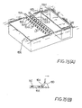
- the brush is comprised of a first brush 15A and a second brush 15B arranged in parallel to each other at a given interval and adapted to be moved together.
- the first brush 15A is provided with a plurality of brush elements 15A1, 15A2, 15A3, etc. spaced at regular intervals in the longitudinal direction of the first brush 15A.
- the second brush 15B is provided with a plurality of brush elements 15B1, 15B2, 15B3, etc.
- the liquid can be coated with a uniform thickness even on a large solidified layer of the model shape as in the case of fabricating a solid model.
- the best result of coating of the liquid was obtained by setting a width L2 of each brush element to 2 mm and setting a spacing L1 between the adjacent brush elements to 1 mm.
- the liquid is carried as the form of waving 15D onto a solidified image 15E by the brush. Accordingly, if the spacing L1 is too wide, a good waving function cannot be obtained. Conversely, if the spacing L1 is too narrow, an amount of the waving 15D becomes large, and accordingly a coating layer 15C of the liquid cannot be desirably formed.
- each brush element if a length of each brush element is too small, the waving 15D cannot be sufficiently formed, and an amount of the liquid to be retained among fibers of the brush element is not sufficient, resulting in defective coating. On the other hand, if the length of each brush element is too large, the amount of the waving 15D becomes large, resulting in defective coating.
- a material, thickness and sweeping speed of the brush element are also important. If the brush element is too hard, the solidified image is broken by the brush element. If the brush element is too soft, or the sweeping speed is too slow, the waving effect cannot be obtained. In these circumstances, these factors should be suitably selected in consideration of the properties of the liquid and the solidified image. In any cases, it is essential that the brush elements are to be spaced at regular intervals in the longitudinal direction of the brush, so as to obtain a good coating.
- the thickness of the coating layer 15C can be made uniform even in the case of sweeping a wide surface of the solidified image 15E.
- the contour corresponding exposure region data is decided in consideration of a three-dimensional offset quantity with respect to a contour of a desired model shape.
- the three-dimensional offset quantity is a quantity for offsetting a contour of a solidified region so as to make the same contact the contour of the desired model shape. Therefore, the contour of the solidified region can be made precisely coincident with the contour of the desired model shape by the exposure according to the data decided in consideration of the offset quantity. Thus, the accuracy of the desired model shape can be greatly improved.
- the solid, hollow or honeycomb model it is possible to desirably select the solid, hollow or honeycomb model according to an intended use of the model. Accordingly, the intended use itself can be widened (for instance, the hollow model can be applied to a casting die), and a modeling time can be shortened according to the intended use of the model to thereby also widen the intended use of the system.
- the supporting structure (support and frame) is formed in the modeling of the desired model shape, the accuracy of the desired model shape can be highly retained.
- a diameter of the beam for forming this supporting structure can be set independently of that for forming the desired model shape. Accordingly, the supporting structure can be easily removed after the modeling is terminated.
- the supporting structure can be formed at a necessary part only, thereby reducing the modeling time.
- the kind, pitch, etc. of the support can be modified in every height of the frame, thereby reducing the modeling time.
- the liquid is coated on the solidified image by using the brush having a plurality of brush elements spaced at regular intervals. Therefore, the liquid can be coated with a uniform thickness in a short time, thereby improving the modeling accuracy and reducing the modeling time.
- system of the preferred embodiment includes various improvements in combination, which is superior to the conventional system.
Landscapes
- Physics & Mathematics (AREA)
- Chemical & Material Sciences (AREA)
- Engineering & Computer Science (AREA)
- Manufacturing & Machinery (AREA)
- Materials Engineering (AREA)
- Mechanical Engineering (AREA)
- Optics & Photonics (AREA)
- Exposure And Positioning Against Photoresist Photosensitive Materials (AREA)
- Heating, Cooling, Or Curing Plastics Or The Like In General (AREA)
Applications Claiming Priority (4)
| Application Number | Priority Date | Filing Date | Title |
|---|---|---|---|
| JP11527190 | 1990-05-02 | ||
| JP115271/90 | 1990-05-02 | ||
| JP297536/90 | 1990-11-02 | ||
| JP2297536A JPH0773884B2 (ja) | 1990-05-02 | 1990-11-02 | 光固化造形装置 |
Publications (2)
| Publication Number | Publication Date |
|---|---|
| EP0459635A1 true EP0459635A1 (de) | 1991-12-04 |
| EP0459635B1 EP0459635B1 (de) | 1995-07-12 |
Family
ID=26453806
Family Applications (1)
| Application Number | Title | Priority Date | Filing Date |
|---|---|---|---|
| EP91303956A Expired - Lifetime EP0459635B1 (de) | 1990-05-02 | 1991-05-01 | Lichthärtungsformungsaparatur |
Country Status (4)
| Country | Link |
|---|---|
| US (1) | US5253177A (de) |
| EP (1) | EP0459635B1 (de) |
| JP (1) | JPH0773884B2 (de) |
| DE (1) | DE69111140T2 (de) |
Cited By (6)
| Publication number | Priority date | Publication date | Assignee | Title |
|---|---|---|---|---|
| DE4134265A1 (de) * | 1991-10-16 | 1993-04-22 | Eos Electro Optical Syst | Stereografie-vorrichtung und -verfahren |
| WO1994016875A1 (de) * | 1993-01-28 | 1994-08-04 | Eos Gmbh Electro Optical Systems | Verfahren und vorrichtung zum herstellen eines dreidimensionalen objekts |
| WO1995029053A2 (en) * | 1994-04-25 | 1995-11-02 | 3D Systems, Inc. | Enhanced building techniques in stereolithography |
| US5965079A (en) * | 1995-04-25 | 1999-10-12 | 3D Systems, Inc. | Method and apparatus for making a three-dimensional object by stereolithography |
| US5999184A (en) * | 1990-10-30 | 1999-12-07 | 3D Systems, Inc. | Simultaneous multiple layer curing in stereolithography |
| CN104827666A (zh) * | 2015-04-30 | 2015-08-12 | 北京敏速自动控制设备有限公司 | 3d打印支撑方法及系统 |
Families Citing this family (13)
| Publication number | Priority date | Publication date | Assignee | Title |
|---|---|---|---|---|
| KR0142904B1 (ko) * | 1992-05-28 | 1998-07-15 | 히데따까 나루까와 | 광경화조형장치와 광경화조형법 |
| JPH06114948A (ja) * | 1992-10-01 | 1994-04-26 | Shiimetsuto Kk | 未硬化液排出口付光硬化造形物とその造形法 |
| JP2853497B2 (ja) * | 1993-01-12 | 1999-02-03 | ソニー株式会社 | 光学的造形装置 |
| JPH0815760B1 (de) * | 1993-04-05 | 1996-02-21 | ||
| WO1995002500A1 (fr) * | 1993-07-15 | 1995-01-26 | Cmet, Inc. | Appareil de modelage par photopolymerisation a fonction de decalage des donnees de triangulation et methode de decalage associee |
| MX9705844A (es) * | 1995-02-01 | 1997-11-29 | 3D Systems Inc | Recubrimiento rapido de objetos tridimensionales con una base en seccion transversal. |
| US5818718A (en) * | 1996-04-01 | 1998-10-06 | University Of Utah Research Foundation | Higher order construction algorithm method for rapid prototyping |
| JP2002331591A (ja) * | 2001-05-08 | 2002-11-19 | Fuji Photo Film Co Ltd | 光造形方法 |
| DE10219983B4 (de) * | 2002-05-03 | 2004-03-18 | Bego Medical Ag | Verfahren zum Herstellen von Produkten durch Freiform-Lasersintern |
| JP4967744B2 (ja) * | 2007-03-26 | 2012-07-04 | 富士通株式会社 | 三次元設計支援方法、三次元設計支援装置及びコンピュータプログラム |
| US9789540B2 (en) * | 2008-02-13 | 2017-10-17 | Materials Solutions Limited | Method of forming an article |
| US8636496B2 (en) * | 2008-05-05 | 2014-01-28 | Georgia Tech Research Corporation | Systems and methods for fabricating three-dimensional objects |
| US9561622B2 (en) | 2008-05-05 | 2017-02-07 | Georgia Tech Research Corporation | Systems and methods for fabricating three-dimensional objects |
Citations (4)
| Publication number | Priority date | Publication date | Assignee | Title |
|---|---|---|---|---|
| FR2583334A1 (fr) * | 1985-06-14 | 1986-12-19 | Cilas Alcatel | Procede et dispositif pour realiser un modele de piece industrielle |
| US4801477A (en) * | 1987-09-29 | 1989-01-31 | Fudim Efrem V | Method and apparatus for production of three-dimensional objects by photosolidification |
| WO1989010256A1 (en) * | 1988-04-18 | 1989-11-02 | 3D Systems, Inc. | Cad/cam stereolithographic data conversion |
| WO1989010254A1 (en) * | 1988-04-18 | 1989-11-02 | 3D Systems, Inc. | Stereolithographic supports |
Family Cites Families (10)
| Publication number | Priority date | Publication date | Assignee | Title |
|---|---|---|---|---|
| US2795758A (en) * | 1956-03-12 | 1957-06-11 | Jr Abry S Cahn | Average speed indicating device |
| JPS56144478A (en) * | 1980-04-12 | 1981-11-10 | Hideo Kodama | Stereoscopic figure drawing device |
| JPS60247515A (ja) * | 1984-05-23 | 1985-12-07 | Oosakafu | 光学的造形法 |
| JPH0634216B2 (ja) * | 1985-07-13 | 1994-05-02 | 大日本印刷株式会社 | 回転体容器の形状決定装置 |
| EP0250121B1 (de) * | 1986-06-03 | 1994-11-02 | Cubital Ltd. | Gerät zur Entwicklung dreidimensionaler Modelle |
| JPH0222035A (ja) * | 1988-03-08 | 1990-01-24 | Osaka Prefecture | 光学的造形法 |
| JPH03501375A (ja) * | 1988-04-11 | 1991-03-28 | オーストラル・エイジアン・レーザーズ・プロプライエタリー・リミテッド | レーザを基本とするプラスチックモデル作成ワークステーション |
| JPH0757532B2 (ja) * | 1988-10-19 | 1995-06-21 | 松下電工株式会社 | 三次元形状の形成方法 |
| US5143663A (en) * | 1989-06-12 | 1992-09-01 | 3D Systems, Inc. | Stereolithography method and apparatus |
| US5071337A (en) * | 1990-02-15 | 1991-12-10 | Quadrax Corporation | Apparatus for forming a solid three-dimensional article from a liquid medium |
-
1990
- 1990-11-02 JP JP2297536A patent/JPH0773884B2/ja not_active Expired - Lifetime
-
1991
- 1991-05-01 EP EP91303956A patent/EP0459635B1/de not_active Expired - Lifetime
- 1991-05-01 US US07/694,333 patent/US5253177A/en not_active Expired - Lifetime
- 1991-05-01 DE DE69111140T patent/DE69111140T2/de not_active Expired - Lifetime
Patent Citations (4)
| Publication number | Priority date | Publication date | Assignee | Title |
|---|---|---|---|---|
| FR2583334A1 (fr) * | 1985-06-14 | 1986-12-19 | Cilas Alcatel | Procede et dispositif pour realiser un modele de piece industrielle |
| US4801477A (en) * | 1987-09-29 | 1989-01-31 | Fudim Efrem V | Method and apparatus for production of three-dimensional objects by photosolidification |
| WO1989010256A1 (en) * | 1988-04-18 | 1989-11-02 | 3D Systems, Inc. | Cad/cam stereolithographic data conversion |
| WO1989010254A1 (en) * | 1988-04-18 | 1989-11-02 | 3D Systems, Inc. | Stereolithographic supports |
Cited By (15)
| Publication number | Priority date | Publication date | Assignee | Title |
|---|---|---|---|---|
| US6264873B1 (en) | 1988-04-18 | 2001-07-24 | 3D Systems, Inc. | Method of making a three-dimensional object by stereolithography |
| US5999184A (en) * | 1990-10-30 | 1999-12-07 | 3D Systems, Inc. | Simultaneous multiple layer curing in stereolithography |
| US6366825B1 (en) | 1990-10-30 | 2002-04-02 | 3D Systems, Inc. | Simultaneous multiple layer curing in stereolithography |
| DE4134265A1 (de) * | 1991-10-16 | 1993-04-22 | Eos Electro Optical Syst | Stereografie-vorrichtung und -verfahren |
| US5582876A (en) * | 1991-10-16 | 1996-12-10 | Eos Gmbh Optical Systems | Stereographic apparatus and method |
| WO1994016875A1 (de) * | 1993-01-28 | 1994-08-04 | Eos Gmbh Electro Optical Systems | Verfahren und vorrichtung zum herstellen eines dreidimensionalen objekts |
| US5536467A (en) * | 1993-01-28 | 1996-07-16 | Eos Gmbh Electro Optical Systems | Method and apparatus for producing a three-dimensional object |
| WO1995029053A3 (en) * | 1994-04-25 | 1996-01-18 | 3D Systems Inc | Enhanced building techniques in stereolithography |
| US6261507B1 (en) | 1994-04-25 | 2001-07-17 | 3D Systems, Inc. | Method of and apparatus for making a three-dimensional object by stereolithography |
| EP1120227A2 (de) * | 1994-04-25 | 2001-08-01 | 3D Systems, Inc. | Fortschrittliche Bautechniken in Stereolithografie |
| WO1995029053A2 (en) * | 1994-04-25 | 1995-11-02 | 3D Systems, Inc. | Enhanced building techniques in stereolithography |
| EP1120227A3 (de) * | 1994-04-25 | 2002-09-18 | 3D Systems, Inc. | Fortschrittliche Bautechniken in Stereolithografie |
| US5965079A (en) * | 1995-04-25 | 1999-10-12 | 3D Systems, Inc. | Method and apparatus for making a three-dimensional object by stereolithography |
| CN104827666A (zh) * | 2015-04-30 | 2015-08-12 | 北京敏速自动控制设备有限公司 | 3d打印支撑方法及系统 |
| CN104827666B (zh) * | 2015-04-30 | 2018-06-19 | 北京敏速自动控制设备有限公司 | 3d打印支撑方法及系统 |
Also Published As
| Publication number | Publication date |
|---|---|
| DE69111140D1 (de) | 1995-08-17 |
| JPH04118222A (ja) | 1992-04-20 |
| DE69111140T2 (de) | 1996-03-28 |
| US5253177A (en) | 1993-10-12 |
| EP0459635B1 (de) | 1995-07-12 |
| JPH0773884B2 (ja) | 1995-08-09 |
Similar Documents
| Publication | Publication Date | Title |
|---|---|---|
| EP0459635B1 (de) | Lichthärtungsformungsaparatur | |
| EP0484183B1 (de) | Lichthärtungsformungsapparatur | |
| US5345391A (en) | Method and apparatus for production of high resolution three-dimensional objects by stereolithography | |
| US6027682A (en) | Thermal stereolithography using slice techniques | |
| US5184307A (en) | Method and apparatus for production of high resolution three-dimensional objects by stereolithography | |
| US5137662A (en) | Method and apparatus for production of three-dimensional objects by stereolithography | |
| US5059359A (en) | Methods and apparatus for production of three-dimensional objects by stereolithography | |
| US6261507B1 (en) | Method of and apparatus for making a three-dimensional object by stereolithography | |
| EP0686480B1 (de) | Stereolithografische Stützen | |
| US4961154A (en) | Three dimensional modelling apparatus | |
| US5031120A (en) | Three dimensional modelling apparatus | |
| US4999143A (en) | Methods and apparatus for production of three-dimensional objects by stereolithography | |
| US9415544B2 (en) | Wall smoothness, feature accuracy and resolution in projected images via exposure levels in solid imaging | |
| EP0484182A1 (de) | Lichthärtungsformungsapparatur mit hoher Präzision | |
| EP0757621B1 (de) | Fortschrittliche bautechniken in stereolithografie | |
| EP1157807B1 (de) | Stereolithographische Formgebungstechniken | |
| JPH0669726B2 (ja) | 光固化造形装置 | |
| Chamberlain | Discrete algorithms for machining and rapid prototyping based on image processing | |
| JPH0778270A (ja) | 物体の曲面作成表示装置 | |
| Combrinck | Development of a cost estimation model for sla prototyping based on volumetric information | |
| Pienaar | Investigation into a low cost StereoLithography system for Rapid Prototyping | |
| Kim | Optimal model-building strategy for rapid prototype manufacturing of sculpture surface |
Legal Events
| Date | Code | Title | Description |
|---|---|---|---|
| PUAI | Public reference made under article 153(3) epc to a published international application that has entered the european phase |
Free format text: ORIGINAL CODE: 0009012 |
|
| AK | Designated contracting states |
Kind code of ref document: A1 Designated state(s): DE FR GB |
|
| 17P | Request for examination filed |
Effective date: 19920514 |
|
| 17Q | First examination report despatched |
Effective date: 19930806 |
|
| GRAA | (expected) grant |
Free format text: ORIGINAL CODE: 0009210 |
|
| AK | Designated contracting states |
Kind code of ref document: B1 Designated state(s): DE FR GB |
|
| ET | Fr: translation filed | ||
| REF | Corresponds to: |
Ref document number: 69111140 Country of ref document: DE Date of ref document: 19950817 |
|
| PLAV | Examination of admissibility of opposition |
Free format text: ORIGINAL CODE: EPIDOS OPEX |
|
| PLBQ | Unpublished change to opponent data |
Free format text: ORIGINAL CODE: EPIDOS OPPO |
|
| PLBI | Opposition filed |
Free format text: ORIGINAL CODE: 0009260 |
|
| 26 | Opposition filed |
Opponent name: EOS GMBH ELECTRO OPTICAL SYSTEMS Effective date: 19960322 |
|
| PLAV | Examination of admissibility of opposition |
Free format text: ORIGINAL CODE: EPIDOS OPEX |
|
| PLBF | Reply of patent proprietor to notice(s) of opposition |
Free format text: ORIGINAL CODE: EPIDOS OBSO |
|
| PLAV | Examination of admissibility of opposition |
Free format text: ORIGINAL CODE: EPIDOS OPEX |
|
| PLBF | Reply of patent proprietor to notice(s) of opposition |
Free format text: ORIGINAL CODE: EPIDOS OBSO |
|
| PLBF | Reply of patent proprietor to notice(s) of opposition |
Free format text: ORIGINAL CODE: EPIDOS OBSO |
|
| REG | Reference to a national code |
Ref country code: GB Ref legal event code: 732E |
|
| REG | Reference to a national code |
Ref country code: FR Ref legal event code: TP |
|
| PLBF | Reply of patent proprietor to notice(s) of opposition |
Free format text: ORIGINAL CODE: EPIDOS OBSO |
|
| PLBF | Reply of patent proprietor to notice(s) of opposition |
Free format text: ORIGINAL CODE: EPIDOS OBSO |
|
| PLBL | Opposition procedure terminated |
Free format text: ORIGINAL CODE: EPIDOS OPPC |
|
| PLBM | Termination of opposition procedure: date of legal effect published |
Free format text: ORIGINAL CODE: 0009276 |
|
| STAA | Information on the status of an ep patent application or granted ep patent |
Free format text: STATUS: OPPOSITION PROCEDURE CLOSED |
|
| 27C | Opposition proceedings terminated |
Effective date: 19970630 |
|
| REG | Reference to a national code |
Ref country code: GB Ref legal event code: IF02 |
|
| PGFP | Annual fee paid to national office [announced via postgrant information from national office to epo] |
Ref country code: GB Payment date: 20100329 Year of fee payment: 20 |
|
| PGFP | Annual fee paid to national office [announced via postgrant information from national office to epo] |
Ref country code: FR Payment date: 20100525 Year of fee payment: 20 |
|
| PGFP | Annual fee paid to national office [announced via postgrant information from national office to epo] |
Ref country code: DE Payment date: 20100430 Year of fee payment: 20 |
|
| REG | Reference to a national code |
Ref country code: DE Ref legal event code: R071 Ref document number: 69111140 Country of ref document: DE |
|
| REG | Reference to a national code |
Ref country code: GB Ref legal event code: PE20 Expiry date: 20110430 |
|
| PG25 | Lapsed in a contracting state [announced via postgrant information from national office to epo] |
Ref country code: GB Free format text: LAPSE BECAUSE OF EXPIRATION OF PROTECTION Effective date: 20110430 |
|
| PG25 | Lapsed in a contracting state [announced via postgrant information from national office to epo] |
Ref country code: DE Free format text: LAPSE BECAUSE OF EXPIRATION OF PROTECTION Effective date: 20110501 |