EP0757621B1 - Fortschrittliche bautechniken in stereolithografie - Google Patents
Fortschrittliche bautechniken in stereolithografie Download PDFInfo
- Publication number
- EP0757621B1 EP0757621B1 EP95917693A EP95917693A EP0757621B1 EP 0757621 B1 EP0757621 B1 EP 0757621B1 EP 95917693 A EP95917693 A EP 95917693A EP 95917693 A EP95917693 A EP 95917693A EP 0757621 B1 EP0757621 B1 EP 0757621B1
- Authority
- EP
- European Patent Office
- Prior art keywords
- vent
- data
- drain
- data set
- drain hole
- Prior art date
- Legal status (The legal status is an assumption and is not a legal conclusion. Google has not performed a legal analysis and makes no representation as to the accuracy of the status listed.)
- Expired - Lifetime
Links
Images


Classifications
-
- G—PHYSICS
- G06—COMPUTING; CALCULATING OR COUNTING
- G06T—IMAGE DATA PROCESSING OR GENERATION, IN GENERAL
- G06T17/00—Three dimensional [3D] modelling, e.g. data description of 3D objects
-
- B—PERFORMING OPERATIONS; TRANSPORTING
- B29—WORKING OF PLASTICS; WORKING OF SUBSTANCES IN A PLASTIC STATE IN GENERAL
- B29C—SHAPING OR JOINING OF PLASTICS; SHAPING OF MATERIAL IN A PLASTIC STATE, NOT OTHERWISE PROVIDED FOR; AFTER-TREATMENT OF THE SHAPED PRODUCTS, e.g. REPAIRING
- B29C64/00—Additive manufacturing, i.e. manufacturing of three-dimensional [3D] objects by additive deposition, additive agglomeration or additive layering, e.g. by 3D printing, stereolithography or selective laser sintering
- B29C64/10—Processes of additive manufacturing
- B29C64/106—Processes of additive manufacturing using only liquids or viscous materials, e.g. depositing a continuous bead of viscous material
- B29C64/124—Processes of additive manufacturing using only liquids or viscous materials, e.g. depositing a continuous bead of viscous material using layers of liquid which are selectively solidified
- B29C64/129—Processes of additive manufacturing using only liquids or viscous materials, e.g. depositing a continuous bead of viscous material using layers of liquid which are selectively solidified characterised by the energy source therefor, e.g. by global irradiation combined with a mask
- B29C64/135—Processes of additive manufacturing using only liquids or viscous materials, e.g. depositing a continuous bead of viscous material using layers of liquid which are selectively solidified characterised by the energy source therefor, e.g. by global irradiation combined with a mask the energy source being concentrated, e.g. scanning lasers or focused light sources
-
- B—PERFORMING OPERATIONS; TRANSPORTING
- B29—WORKING OF PLASTICS; WORKING OF SUBSTANCES IN A PLASTIC STATE IN GENERAL
- B29C—SHAPING OR JOINING OF PLASTICS; SHAPING OF MATERIAL IN A PLASTIC STATE, NOT OTHERWISE PROVIDED FOR; AFTER-TREATMENT OF THE SHAPED PRODUCTS, e.g. REPAIRING
- B29C64/00—Additive manufacturing, i.e. manufacturing of three-dimensional [3D] objects by additive deposition, additive agglomeration or additive layering, e.g. by 3D printing, stereolithography or selective laser sintering
- B29C64/40—Structures for supporting 3D objects during manufacture and intended to be sacrificed after completion thereof
Definitions
- This invention relates a method of and an apparatus for providing a three-dimensional object to be built layer-by-layer by selective solidification of a solidifiable medium, e.g. through application of the principles of stereolithography.
- stereolithography which is described in U.S. Patent No. 4,575,330 (hereinafter the '330 patent).
- a three-dimensional object is formed layer-by-layer in a stepwise fashion out of a material capable of physical transformation upon exposure to synergistic stimulation (e.g., fluid or fluid-like material such as a photopolymer, sinterable powder, or a bindable powder).
- synergistic stimulation e.g., fluid or fluid-like material such as a photopolymer, sinterable powder, or a bindable powder.
- layers of liquid photopolymer are successively formed at the working surface of a volume of the liquid photopolymer contained in a container.
- the working surface is the upper surface of the liquid, wherein the surface is a free surface as its position is not restrained by a physical barrier.
- a stereolithography system will typically form a three-dimensional object in accordance with a corresponding object representation, which representation may be formed in a CAD system or the like. Before such a representation can be used however, it must be sliced into a plurality of layer representations. The stereolithography system will then, in the course of building up the object in a stepwise layer-by-layer buildup, selectively expose the untransformed layers of material in accordance with the layer representation to form the object layers, and thus, the object itself.
- PCT Pub. WO 92/20505 describes various techniques for building an object through stereolithography with reduced post-cure distortion.
- U.S. Patent No. 5,130,064, PCT Pub. WO 91/06378, and PCT Pub. WO 92/20505 describe continuous skinning and weaving techniques for reducing post-cure distortion.
- U.S. Patent No. 5,184,307 describes in great detail the presently preferred stereolithographic apparatus, as well as various methods to form parts therewith.
- Two reference manuals, The SLA-250 User Reference Manual and The SLA-500 Reference Manual accompanied U.S. Patent Application Serial Number 429,435 (now U.S. Patent No. 5,130,064) as Appendices B and C respectively.
- U.S. Patent No. 5,076,974 describes off-absorption-peak wavelength post curing of parts which were formed based on the primary approach to building stereolithographic parts.
- U.S. Patent No. 4,999,143 describes the use of web supports to support and minimize curl in a part being formed.
- U.S. Patent No. 5,182,056 describes the use of multiple penetration depths in the stereolithographic process, along with the use of beam profile characteristics in combination with resin parameters to predict various cure parameters associated with the creation of stereolithographic parts. This application also describes the role of beam profile information in the creation of skin fill and discusses various multiple wavelength curing methods for reducing part distortion.
- U.S. Patent No. 5,234,636 discloses various methods of finishing a stereolithographic part surface to smooth out discontinuities in a post-processing step.
- PCT Publication No. WO 90/03255 discloses the use of a doctor blade for obtaining a uniform coating of resin of known thickness over each cross-section of a stereolithographic part as well as a system for maintaining a known surface level of the building material as the part is being built.
- a problem with prior systems relates to parts intended for use in investment casting applications. With traditional stereolithographic methods, problems have been experienced draining unsolidified material from the internal recesses of such parts. Another problem has been the collapsing of outer walls of such parts after the unsolidified material has been drained.
- the invention provides a method for placing vents and drains in a three-dimensional object representation such that unsolidified material is able to drain from the object after it is built through stereolithography.
- EP-A-0590957 addresses the problem of forming a honeycomb-like structure within an object whilst allowing communication for the flow of unsolidified material between cells of the structure through liquid ejecting ports. These ports are formed by eliminating or offsetting some of the ribs, or forming holes in some of the ribs.
- EP-A-0250121 relates to the formation of three-dimensional objects, and discloses the formation of a drainage conduit and an air conduit. These conduits are formed to a region which was never intended to form part of the object, in particular to a trapped void surrounded by the object. An area not forming part of the object is determined by finding a voxel having a value of 0. Then, the value of voxels overlying and underlying this voxel are changed to 0 so these voxels form a conduit.
- a method of providing a three-dimensional object to be built layer-by-layer by selective solidification of a solidifiable medium in which at least one region of the object, which is indicated as being solid in a first data set defining the object, is built according to a second data set derived from the first data set as a structure having spaces containing unsolidified medium between solidified structural elements, said second data set provides that said object is built to have one or more surfaces defining the said region which close off said spaces from communication with the exterior of the object, in which at least one of said surfaces is provided with a vent or drain hole allowing evacuation of unsolidified material from said spaces.
- an apparatus for providing a three-dimensional object to be built layer-by-layer by selective solidification of a solidifiable medium in which at least one region of the object, which is indicated as being solid in a first data set defining the object, is built according to a second data set derived from the first data set as a structure having spaces containing unsolidified medium between solidified structural elements, the apparatus including a second data set generating means to generate said second data set including one or more surfaces defining the said region which close off said spaces from communication with the exterior of the object in which at least one of said surfaces is provided with a vent or drain hole allowing evacuation of unsolidified material from said spaces.
- the present invention preferably utilizes a combination of two .CTL representations of the object which are scaled relative to each other with the normal orientations of the triangles reversed on the relatively scaled down representation.
- Methods to form an object utilizing different building parameters in two or more shell-like zones and method to obtain the data necessary for such building are disclosed.
- the object may be divided into an exterior zone of specified thickness and an interior zone.
- These methods utilize a combination of three or more object representations scaled relative to each other, with the normal orientations of the triangles of some representations reversed, and with pairs of consecutive representations utilized to define distinct zones.
- This invention provides that objects are formed with a build style that promotes the draining of untransformed building material from the internal portion of it.
- the objects produced according to these techniques have particular usefulness as investment casting patterns.
- the ability of the untransformed building material to be removed from the internal portions of the object is a result of using wide spaced hatch patterns that are periodically offset and/or using at least some hatching patterns that result in broken lines of transformed material. Multiple skins and/or multiple boundaries may also be used.
- more complex embodiments are possible that use different building parameters for different internal portions of the object Some of these more complex embodiments use minimal internal grid structure near the surfaces and boundaries of the object and use more internal grid structure deep within the object. Other embodiments use some grid structure near the surfaces and boundaries of the object but use less or no grid structure in the deep internal regions of the object.
- an improved stereolithographic method may comprise the combined use of hatch with nonconsecutive skin fill in more than the up- and down-facing features.
- an improved stereolithographic method may comprise the method of reducing exposure where vectors intersect and providing discontinuities in skin fill to avoid multiple vector exposure in regions where hatch vectors have been provided.
- layer comparisons are required to determine with which final cross-sections each portion of each initial cross-section will be associated and each portion's appropriate cure depth.
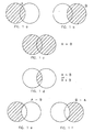
- FIG. 1 graphically depicts these Boolean operations.
- the shaded portion within the circle of Figure 1A depicts a first region known as region A.
- the other circle represents the physical placement of a second region, known as region B, relative to region A.
- the shaded portion within the circle of Figure 1B depicts region B, while the other circle represents region A.
- the shaded portion of Figure 1C represents the result of the Boolean union of regions "A" and "B" (A+B).
- FIG. 1D represents the Boolean intersection of regions "A" and "B" (A ⁇ B, or alternatively A * B).
- FIG. 1E and 1F respectively, depict the result of the Boolean differencing operation of A minus B and B minus A.
- CSlice also uses the NOT operator (-). This operator is equivalent to a differencing operator. Thus the NOT operator reverses whatever it operates on.
- the above Boolean operations have been found to be useful in the CSlice program, of course other Boolean operations can be used as needed.
- the preferred implementation of the horizontal comparison technique is to offset selected points, lines or surfaces known amounts and utilize the offset elements to define new cross-sectional regions.
- a preferred embodiment utilizes positive and negative line width compensation type offsets of existing cross-sectional boundaries.
- Techniques for performing line width compensation are described in detail in U.S. Patent Nos. 5,321,622 and 5,184,307, both previously referenced.
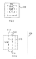
- Figure 2 depicts a simple square cross-section of an object having a boundary 500 as well as first, second, and third offset secondary boundaries, labeled 502, 504 and 506, respectively. These secondary boundaries were created using a line width compensation technique.
- Offset boundary 506 may have been created directly from boundary 500 or alternatively may have been created from boundary 504 which may have been created from boundary 502 which in turn was created from boundary 500.
- any one or all of the offset boundaries could be used to define separate exposure regions for the object.
- the interior of 506 might be one exposure region
- the region between 502 and 506 might be a second exposure region
- the region between 502 and 500 might be a third exposure region.
- the boundaries on which the above offsets are made may be the overall cross-sectional boundaries for a cross-section or alternatively one or more of the down-facing, up-facing or continuing boundaries of the cross-section, either taken in combination or alone.
- a preferred embodiment utilizing this technique involves making improved patterns for investment casting.
- the horizontal comparisons operate on the Layer Boundary (LB) regions of each cross-section to divide them into three regions.
- the first region is that closest to the original LB boundaries and is approximately 15 - 30 mils (0.4 to 0.8 mm) wide.
- This first region forms a completely solidified shell region.
- the solidification of the first region may occur via multiple overlapping offset boundaries (preferred technique) or alternatively it may be filled by a utilization of skin vectors.
- the second region borders the first region and proceeds deeper into the cross-section another 50 to 100 mils (1.3 to 2.5 mm).
- This region is solidified using minimal structure, e.g. a very wide spaced hatch, or possible a broken hatch pattern, that may be used on only periodic layers.
- Each hatch line might be solidified via a single hatch vector or by two or more hatch vectors which are offset from one another. For example, it might be used once every 35 to 150 mils (0.9 to 3.8 mm) and be offset with consecutive uses. Alternatively, for example, it might be used every 100 to 150 mils (2.5 to 3.8 mm) but when used it may be exposed on a series of two or three, or more, consecutive layers without offset. The spacing between the vectors might be 100 to 250 mils (2.5 to 6.4 mm).
- the third region occupies the rest of the original LB region.
- the third region is solidified with a tighter hatch pattern, or one with fewer breaks, than that used in the second region. For example, hatch with a spacing of 100 to 150 mils (2.5 to 3.8 mm) might be used on every layer and offset periodically.
- This embodiment offers a strong outer shell which is directly supported by a very fine grid structure, which in turn is supported by a more rigid grid structure.
- the utilization of the horizontal comparison technique allows implementation of an internal grid structure that is fine enough near the object surfaces to allow resin drainage but structurally rigid enough in the deep interior portions of the object to provide adequate support for large structures so as to ensure structural integrity. Without the horizontal comparison techniques described herein, this embodiment could not readily be implemented on an automated basis.
- these horizontal comparison techniques will be combined with Simultaneous Multi Layer Comparison (SMLC) techniques such as disclosed in WO 92/08200, US 5,321,622 and US 5,192,469 in order to produce a pattern with multiple skins as well as with thicker boundary regions.
- SMLC Simultaneous Multi Layer Comparison
- the combination embodiment is readily implemented by deriving the multiple skins first by utilization of the SMLC techniques and then using the Horizontal comparison technique to further dissect the Final Layer Boundary FLB regions resulting from the layer comparisons.
- the most preferred embodiment extends the last embodiment one step further, by continuing the layer comparison into one or more layers immediately above the multiple down-facing skins and immediately below the multiple up-facing skins so as to provide region designations that allow the regions immediately above and below the down-facing and up-facing surfaces, respectively, to be transformed using a minimal amount of hatch.
- these regions extend beyond the skins by 25 to 150 mils (0.6 to 3.8 mm) and most preferable by 70 to 100 mils (1.8 to 2.5 mm) and are solidified using a series of point exposures, e.g. columns, which may be one, two, three or more linewidths in diameter and spaced from each other by 25 to 150 mils (0.6 to 3.8 mm).
- the columns may not be circular in cross-sectional dimension but may take on some other shape, such as small crosses, boxes or the like.
- Figure 4 depicts such a region 564.
- Figure 4 depicts a side view of a portion of an object, wherein lines 550 define the outer surface of the object, region 552 indicates an up-facing skin, and regions 558 depict the boundaries of continuing regions (FLB). Regions being skinned due to the use of multiple skins are indicated by numerals 552 and 554, while regions being transformed due to the widened solidification zone around the FLBs (e.g.
- region 564 should be solidified but is not. This is due to blanket decision not to utilize widened cure zones around the FLB that are adjacent to skinned regions. The extra care involves utilization of additional comparisons to determine whether or not corresponding FLBs exist on the next consecutive layer and whether or not they are adjacent to skin regions. If such a next consecutive layer is found then the corresponding FLBs for the present layer, and probably one or more previous layers, are supplied with the widened solidification zone. Other horizontal comparison techniques are also possible. For example, regions on a cross-section can be designated by their distance from a line which lies parallel to the plane of the cross-section and which either intersects the cross-section or is outside it.
- FIG. 3 A cross-section is depicted which is defined by boundary 500.
- a line 508 is depicted outside the cross-section.
- line 508 is offset from its original position by known amounts.
- the offset line can be used to create secondary boundary lines for the cross-section.
- These secondary boundary lines can be used to define regions of the object which are located at particular distances from the original line 508.
- Numerals 510, 512 and 514 depict such secondary boundary lines. If it is desired to define actual boundary loops based on the secondary lines, the region between two secondary boundary lines can considered an imaginary solid which is partially defined by the secondary boundary lines.
- this imaginary solid region two additional line segments are attached to the secondary boundaries wherein the attachment is made on either side of the regions which contain the actual cross-section. Two such lines are depicted in the Figure with numerals 516 and 518.
- the fully defined imaginary solid region can be intersected with the cross-sectional region defined by boundary 500 so as to yield the region common to both. This common region is located at a given distance from the original line 508.
- This type of comparison can find utility in a variety of situations. For example, if the line 508 represents an axis around which the completed object is going to be rotated then the moment of inertia from each cross-sectional strip can be used to determine the overall moment of inertia for the object. Appropriate cure parameters can be applied to each strip so as to give the object an overall moment of inertia or to give the strips at similar distances from the line 508 the same cure parameters.
- a point like region can be defined from which a series of negative compensations (expansions) will be performed in order to determine the distance between each portion of the cross-section and the initial point.
- the initial point may be defined as a small square, hexagon, octagon, or other polygon which will give the appropriate geometric shape with each expansion.
- the horizontal comparison techniques can be utilized to help automate the recoating process. If positive multiple line width compensations, i.e. reductions, are made, wherein each compensation step has a known width, wherein the number of steps are counted, and wherein the compensations are repeated until the entire cross-section has been traversed, one can determine the maximum distance from the outer portions of the cross-section to its deepest internal point. This distance determines the maximum distance resin must travel over the surface of the previous cross-section in order to reach the most distance point on the cross-section. This distance is the diameter of what is known as the critical circle. One can correlate the critical circle diameter to the dip depth required to most rapidly form a preliminary coating over the previous cross-section. This in turn can lead to a reduction in build time as the net dipping times can be reduced. Thus before performing the recoating process for each cross-section a look up table or the like can be consulted to determine the appropriate dipping parameters to use during recoating.
- a look up table or the like can be consulted to determine the appropriate
- the recoating process can be further automated by utilizing a combination of the horizontal and vertical comparison techniques to characterize the object configuration over which a smoothing member is passed. Though, many potential object configurations can exist, the characterization of these configurations can hopefully be reduced to a tolerable set.
- the set of different configurations may be divided into two or more categories. Preferably, the set of distinct configuration will have less than 10 to 20 categories. For each predefined category, the optimum recoating parameters can be determined and stored for use during the recoating process for each layer. There are various recoating parameters that can be varied depending on the object configuration.
- these parameters may include: (1) the number of sweeps, (2) the clearance between the smoothing member and object surface during each sweep, (3) the velocity of each sweep, (4) the gap between the bottom of the smoothing member and the desired building level, (5) the sweeping direction, etc.
- another recoating parameter which may be varied might include the type of device utilized, e.g. a flexible blade or a rigid blade, a rotating device, a blade with teeth or multiple appendages, etc.
- Another recoating parameter which might be varied is the orientation of the object relative to the sweeping device, e.g. the object may be formed on a platform that can be rotated in the horizontal plane.
- the rotatable platform that can be turned to an appropriate direction for sweeping then rotated back for during of the next layer or alternatively solidification of the next layer can occur by rotating the orientation of the exposure pattern to be utilized, followed by another rotation of the object for recoating purposes when appropriate and possibly additional rotations and offsets of the exposure pattern.
- variables may be utilized in categorizing the object configuration. For example, these variables may include: (1) layer thickness, (2) maximum depth of the widest trapped volume, (2) the maximum width of the deepest trapped volume, (3) the cross-sectional area of the previously solidified layer, (4) the primary orientation and dimensions of the largest trapped volume, and (5) the primary orientation and dimensions of the previously solidified layer.
- a smoothing member in the stereolithographic recoating process e.g. a doctor blade, is described in PCT Pub. WO 90/03255, which is incorporated herein by reference as if set forth in full.
- QUICKCAST is any of a number of different building styles which allow untransformed material to be removed from the interior of the walls of the object after formation (previous embodiments are described in PCT Pub. WO 92/08200 and PCT Pub. WO 92/20505).
- the ability of the untransformed building material to be removed from the internal portions of the object is a result of using wide spaced hatch patterns that are periodically offset and/or using at least some hatching patterns that result in broken lines of transformed material, for example as described previously. Multiple skins and/or multiple boundaries may also be used.
- the drained objects are typically used as investment casting patterns. Since these build styles produce objects with little distortion and since they also use relatively small amounts of building material, they are considered practical building styles for many applications.
- QUICKCAST Build Style The building technique which produces drainable parts for use as investment casting patterns has become known as a QUICKCAST Build Style. This is a generic name that can be applied to any of a variety of stereolithographic build styles that can be used in forming objects with hollow or drainable walls.
- Presently preferred QUICKCAST building techniques use widely spaced cross-hatch vectors that are derived from hatch paths that are a fixed for a number of layers. This causes the hatch lines that are produced from the hatch vectors to overlay each other for a number of layers. After forming several layers, the hatch paths are shifted and remain in this altered state for a number of layers after which they are shifted back to their original locations. In effect, the shifting of hatch lines only occurs periodically. The most appropriate hatch spacing and hatch height before shifting are resin dependent. It has also been found that these parameters can also be dependent on object configuration.
- the preferred thickness of layers before offset is in the range of 70 to 130 mils (1.8 to 3.3 mm) and more specifically between 80 to 120 mils (2.0 to 3.0 mm) most preferably about 100 mils (2.5 mm) plus or minus 5 mils (0.1 mm) and maybe 10 mils (0.2 mm).
- the height before offset it may be advantageous to reduce the height before offset to as low as 30 or 40 mils (0.8 to 1.0 mm).
- the height before offset it may be advantageous to reduce the height before offset to as low as 30 or 40 mils (0.8 to 1.0 mm).
- curing hatch vectors they are typically supplied an exposure in excess of the layer thickness to ensure that the layers adhere to one another.
- This excess cure depth is typically 5 to 6 mils (0.1 mm) or more.
- This excess cure depth results in a decrease vertical dimension of the openings formed by the offsetting of hatch. This decrease in opening height must be considered when determining the number of layers to draw before offsetting.
- the horizontal spacing of the hatch vectors is also bounded by opposing requirements.
- the spacing of the hatch vectors is too wide, several problems could occur: (1) they might supply inadequate support for the skin and boundary regions surfacing the object, (2) they might provide inadequate strength for overall object integrity, or (3) they might create trapped volumes that could make recoating difficult.
- a spacing of approximately 120 to 180 mils (2.0 to 3.0 mm) is preferred; more specifically a spacing of 130 to 170 mils (1.8 to 3.3 mm) is preferred; and most preferably a spacing of approximately 150 mils (3.8 mm) is used.
- the presently preferred building materials for stereolithographically forming investment casting patterns are hybrid epoxy resins, SL 5170 and SL 5180. These resins are manufactured by Ciba Geigy of Basel Switzerland and sold by 3D Systems, Inc. of Valencia, California.
- the SL 5170 is used in combination with a HeCd laser emitting 325 nm radiation
- SL 5180 is used in combination with an argon-ion laser emitting 351 nm radiation or a krypton laser emitting 351 and 356 nm radiation.
- the preferred layer thickness for SL 5170 is 4 mils (0.1 mm) with a boundary vector overcure of 7 mils (0.2 mm), and other exposure parameters including a hatch vector overcure of 5 mils (0.1 mm) in combination with a triangular hatch pattern, a skin vector spacing of 4 mils (0.1 mm) and a net skin cure depth of 12 mils (0.3 mm),
- the preferred layer thickness for the SL 5180 resin is 6 mils (0.2 mm) with a triangular pattern and other exposure parameters including a boundary overcure of 7 mils (0.2 mm), a hatch overcure of 6 mils (0.2 mm), and with other parameters similar to those used for the SL 5170 resin.
- the most preferred temperatures are equivalent to the temperatures used in forming the objects on the SLA. This temperature range is typically 28 to 30 degrees C. If the temperature is increased significantly above this level increase in object distortion due to temperature has been found to out weight any advantage gained by decreased drainage time.
- These new features may include: (1) formation of multiple down-facing skins so as to increase the structural integrity of down-facing features, (2) no utilization of hatch vectors when forming at least the first layer of down-facing skin which minimizes any wafflish appearance of these features, (3) formation of multiple up-facing skins to increase the structural integrity of the up-facing features, (4) no utilization of hatch vectors when forming at least the last layer of up-facing skin thereby minimizing any wafflish appearance that might result, (5) utilization of multiple boundaries which are offset from one another when forming the exterior portions of each cross-section thereby increasing the structural integrity of the walls of the object, (6) exposing the most exterior boundary last on each cross-section, (7) utilization of wider spaced hatch vectors than possible with the previous version, thereby decreasing drainage time and decreasing the likely hood of trapping pockets of resin in tight regions, (9) utilization of different hatching styles than those preferred for the previous version, eg., rectangular or hexagonal patterns,(10) automatic creation of holes in selected surfaces of the object so as to eliminate or reduce the
- the most preferred parameters when using SL 5170 are: (1) use of 6 mil (0.15 mm) layers; (2) use of 4 boundaries spaced apart by 4 mils (0.10 mm) per consecutive boundary; (3) use of 3 up-facing and down-facing skins exposed using both X- and Y-fill vectors with each set of fill vector supplied with sufficient exposure to yield an 8 mil (0.20 mm) cure depth with no hatch on the first down-facing layer or the last up-facing layer, (4) use of a hatch spacing of between 150 and 350 mils (3.8 to 8.9 mm) and more preferably between 200 and 300 mils (5.1 and 7.6 mm) and most preferably approximately 250 mils (6.4 mm); (5) use of a square hatch pattern, though eventually a hexagonal pattern might be better,
- the hatch vectors are not drawn as continuous lines but are periodically provided with gaps that are sufficiently large in both the horizontal and vertical dimensions so as to allow flow of the liquid resin and its eventual drainage from the interior portions of the walls of the object.
- the spacing of the hatch vectors is preferably equal to or greater than 150 mils (3.8 mm).
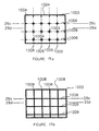
- Figure 17a depicts the boundary 1002 for an arbitrary layer and the hatch pattern 1004 to be cured in association with that layer.
- the hatch lines to be cured on this layer lie on a square grid of hatch paths 1006 (i.e., the dash lines) but only the regions near the intersections of the paths are actually solidified. If the spacing between the consecutive hatch paths is, for example, 150 mils (3.8 mm), the length of the individual lines solidified on each path may be between 30 and 50 mils (0.8 and 1.3 mm). This results in open horizontal regions of 100 to 120 mils (2.5 to 3.0 mm) between each solidified line on each path.
- FIG 17b depicts a hatch pattern 1008 to be cured in association other layers of the object.
- This hatch pattern is based on the same grid 1006 of hatch paths that the short hatch 1004 was based on. Thus it is ensured that the hatch lines lie a top one another.
- the hatch patterns 1004 and 1008 alternate on a periodic basis. This alternation of the patterns should occur so that the object is formed with sufficient structural integrity. At the same time the alternations should be performed using a spacing such that the vertical dimensions of the openings are sufficiently large to allow efficient flow of the liquid material, while at the same time not spaced so far apart so as to form structures that will trap liquid in features thinner than 80 to 120 mils (2.0 to 3.0 mm).
- the 1004 hatch pattern is used on consecutive layers until a height of 80 to 120 mils (2.0 to 3.0 mm) is obtained followed by use of the 1008 hatch pattern on the next consecutive layers for a height of 20 to 40 mils (0.5 to 1.0 mm).
- This layer-to-layer build up process is depicted in the object side view as shown in Figures 17c and 17d which are taken from vertical cuts through a plane of stacked hatch paths and a plane intermediate to the stacked hatch paths.
- this embodiment is less susceptible to trapping volumes of liquid that can result in solidified regions thicker than the acceptable level.
- Other hatch patterns are possible which can lead to the same desired result.
- These other hatching patterns might be based on other hatch path patterns or spacings and/or other combinations of solid and broken hatch, or even of broken and broken hatch.
- each hatch line may actually be formed by exposing two more slightly off-set hatch vectors.
- Another embodiment may not allow the hatch lines on layers containing broken hatch lines to contact the boundaries of the region.
- a minimum separation distance between can be implemented by creating a temporary boundary for hatching purposes via a line width type of compensation of the original boundary.
- the second embodiment is similar to the first embodiment above, except that some of the broken hatch lines are allowed to extend further and thus provide more stability to the structure.
- An additional QUICKCAST building style embodiments exist that can be used in combination with the any of the above embodiments. Some of these additional embodiments involve the use of different hatching patterns at different positions within the object depending on how far the positions are from the surface of the object.
- the hatch When using a single skin and single boundary offset hatch embodiment, the hatch must be relatively closely spaced and offset frequently to ensure that the surfaces of the object are adequately supported and that large regions of liquid won't be trapped within the object.
- closely spaced hatch and frequently offset hatch implies that the flow paths are relatively small and thus considerable time may be required to complete the necessary drainage. Since the internal integrity of the object is less important than the external integrity, as one moves further from the surfaces of the object the spacing of the hatch vectors can be increased significantly.
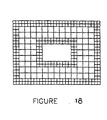
- the first step in implementing an embodiment that changes hatch line quantity as one moves deeper into an object is to determine how deep one is into the object.
- FIG. 18 depicts a cross-section which uses two different hatch types depending on the distance the region is from the surfaces of the cross-section.
- the use of the information about a region's depth into the object can be utilized in an opposite manner to that of the previous embodiment Especially when using a multiple skin and multiple boundary embodiment, one can use less internal structure to support the surfaces and external boundaries of the object. This use of less support structure can lead to much freer drainage of the untransformed material within and near the external surfaces of the object. However, though the surface areas are much more rigid one must still be concerned about overall structural integrity of the object. Based on these concerns this embodiment uses minimal internal structure near the surfaces and boundaries of the object and more structure when one is further from the external features of the object. For example, the hatch spacing may be large when one is within a particular distance to the surface of the object and/or one can ensure that only broken hatch vectors are used within the given distance of the surface.
- horizontal comparisons can be of particular advantage in implementing advanced QUICKCAST build styles.
- the horizontal comparisons operate on the LB regions of each cross-section to divide them into three regions.
- the first region is that closest to the original LB boundaries and is approximately 15-30 mils (0.4 to 0.8 mm) wide.
- This first region forms a completely solidified shell region.
- the solidification of the first region may occur via multiple overlapping offset boundaries (preferred technique) or alternatively it may be filled by a utilization of skin vectors.
- the second region borders the first region and proceeds deeper into the cross-section another 50 to 100 mils (1.3 to 2.5 mm). This region is solidified using minimal structure, e.g.
- Each hatch line might be solidified via a single hatch vector or by two or more hatch vectors which are offset from one another. For example, it might be used once every 25 to 150 mils (0.6 to 3.8 mm) and be offset with consecutive uses. Alternatively, for example, it might be used every 100 to 150 mils (2.5 to 3.8 mm) but when used it may be exposed on a series of two or three, or more, consecutive layers without offset.
- the spacing between the vectors might be 100 to 250 mils (2.5 to 6.4 mm).
- the third region occupies the rest of the original LB region.
- the third region is solidified with a tighter hatch pattern, or one with fewer breaks, than that used in the second region. For example, hatch with a spacing of 100 to 150 mils (2.5 to 3.8 mm) might be used on every layer and offset periodically.
- This embodiment offers a strong outer shell which is directly supported by a very fine grid structure, which in turn is supported by a more rigid grid structure.
- the utilization of the horizontal comparison technique allows implementation of an internal grid structure that is fine enough near the object surfaces to allow resin drainage but structurally rigid enough in the deep interior portions of the object to provide adequate support for large structures so as to ensure structural integrity. Without the horizontal comparison techniques described earlier, this embodiment could not readily be implemented on an automated basis.
- a more preferred embodiment will combine the horizontal comparison generated regions with multiple skins generated by vertical layer comparisons. This combination embodiment is readily generated by the techniques described in the above referenced application.
- the most preferred embodiment extends the last embodiment one step further, by continuing the layer comparisons into one or more layer immediately above the multiple down-facing skins and immediately below the multiple up-facing skins so as to provide region designations that allow the regions immediately above and below the down-facing and up-facing surfaces, respectively, to be transformed using a minimal amount of hatch.
- these regions extend beyond the skins by 25 to 150 mils (0.6 to 3.8 mm) and most preferably by 70 to 100 mils (1.8 to 2.5 mm) and are solidified using a series of point exposures, e.g. columns, which may be one, two, three or more line widths in diameter and spaced from each other by 25 to 150 mils (0.6 to 3.8 mm).
- the columns may not be circular in cross-sectional dimension but may take on some other shape, such as small crosses, boxes, or the like.
- a preferred embodiment, when using the SL 5170 resin and the SL 5180 resin is called ACES building styles. Only boundaries and X and Y skin fill are used on each portion of each cross-section. The sequence of exposing the X and Y vectors is alternated from layer to layer. The first set of skin vectors exposed are given an exposure that results in a net cure depth of slightly under one layer thickness. When the second set of vectors expose the material, the increase in cure depth results in adhesion. Typically, identical exposures are applied to both sets of skin vectors. However, it is possible to use a larger exposure on the second set than that used on the first set.
- the preferred layer thicknesses are 4 mils (0.10 mm) for SL 5170 and 6 mils (0.15 mm) for SL 5180. Though not preferred it is possible to utilize hatch vectors during exposure of the cross-sections, furthermore it is possible to use the ACES building style on a portion of a cross-section or object and some other building style on another portion of the cross-section or object.
- the ACES build style yields highly translucent parts.
- predip delay For the ACES building style when using SL 5170 the time period is typically between 10 and 30 seconds whereas when using SL 5180 it is typically between 45 and 90 seconds.
- the QUICKCAST build styles when using SL 5170 the predip delay is typically between 0 and 15 seconds whereas when using SL 5180, it is typically 10 to 30 seconds. Exact values of predip delay can be obtained from minimal trial and error for particular part geometries.
- predip delay As a technique for eliminating or at least minimizing the impact that predip delay has on part building time, it is possible to use a smart exposure pattern that exposes critical areas first, followed by exposure of less critical areas. In effect, the count down of the predip delay time can begin as soon as all critical regions have been exposed. Thus depending on how long the exposure of the less critical regions takes, the predip delay is either eliminated or at least reduced.
- Critical areas can be considered external boundary regions and external skin regions, with only a grid structure of the non-external regions being considered at least marginally critical.
- One potential work around involves scanning external regions first followed by scanning a gird pattern in the non-external regions, after which predip delay count down begins, followed by exposure of the remaining non-external regions.
- VIEW is configured to display a representation of the object in the .STL format.
- the .STL format is a tesselated triangle format, in which the triangles substantially span the surface of the object, and each triangle is represented by its three vertices (in an exemplary embodiment, the three vertices are each represented by three floating point numbers, and are ordered in accordance with the "right-hand rule") and a normal vector (also represented in an exemplary embodiment by three floating point numbers representing the i, j, and k components of the normal). Additional details about the .STL format are available in U.S. Patent Nos. 5,059,359; 5,137,662; 5,321,622; and 5,345,391.
- the .CTL format provides several advantages relative to the .STL format which are relevant to VIEW. The first is that it facilitates the execution of scaling and rotation operations. The second is that, through appropriate selection of the delta value (the level of acceptable rounding error), detail which is unnecessary from the standpoint of VIEW can be eliminated, enabling the resultant object to be efficiently displayed on relatively slow graphic display devices.
- a first embodiment of an automatic method of adding vents and drains to an object involves displaying a representation of the object, whether in the .CTL or .STL format, and automatically displaying to a user the flat triangles involved in representing the object. Only the flat triangles are highlighted, since in this embodiment, a vent can only be placed in a flat up-facing triangle, while a drain can only be placed in a flat down-facing triangle.
- VIEW is able to determine which triangles are candidates for placement of a vent or drain through the normal vector associated with the triangle: the k component of the normal of all flat triangles is either 1 or -1, with the value of 1 being associated with up-facing triangles, and the value of -1 being associated with down-facing triangles.
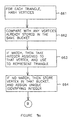
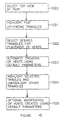
- the process for creating vents involves the steps illustrated in Figure 19.
- the user selects the option of displaying a top view of the part.
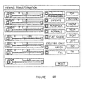
- the user clicks onto the "Top” button using the "Viewing Transformation” window provided by VIEW, which is illustrated in Figure 25.
- the "Viewing Transformation” window provides a user with the capability to specify various characteristics about the display, such as whether to transpose or rotate it in one or more coordinates, whether to zoom it, the perspective of the display (i.e., top, bottom, front, rear, right, light, isomorphic, or tesselated triangle), and the shading of the display. Examples of a display of cube in which one or more of these parameters have been varied are illustrated in Figures 22, 23, 24, and 26.
- the next step is to highlight the candidate triangles in which a vent can be placed, which, as discussed, are the flat up-facing triangles.
- This step is accomplished by clicking on the "Display Vent Triangles" bar provided in the "Vents and Drains” window, both of which are illustrated in Figure 21.
- the flat up-facing triangles are highlighted in the display with a particular color, e.g., blue.
- the next step is to identify selected ones of the flat up-facing triangles in which vents are to be created. This is accomplished by moving the mouse arrow into any of the highlighted triangles, and pressing one of the mouse buttons. The selected triangle will then be highlighted in a different color, e.g., white, than the other up-facing triangles. In this step, more than one triangle can be selected.
- the next step, identified with numeral 1023 in Figure 19 is the automatic creation of the vents. This is accomplished by clicking on the "Create” button displayed as part of the "Vents and Drains” window (illustrated in Figure 21). The result is that a vent is created in every one of the selected triangles using default values. Simultaneously, as depicted by the step identified with numeral 1024 in Figure 19, the vents, and the triangles in which they appear, are highlighted with an appropriate color, e.g., blue. All the other flat up-facing triangles are unhighlighted.
- FIG. 22 to 24 and 26 A vent which has been created in accordance with this process is illustrated in Figures 22 to 24 and 26 (the vent in all four figures is identified with numeral 1032). As discussed, the four figures represent different perspectives and shading of the top of the object.
- the vents when first created, have a default shape and size.
- the default shape of the vent is a circle, but it should be appreciated that other shapes are possible.
- the resins presently preferred for 3D Systems' commercial products Cibatool SL 5170 for the SLA-190/250, and Cibatool SL 5180 for the SLA-500
- the final step illustrated in Figure 19 allows a user to change the default size of the vents, and also allows the user to move a vent (in the X-Y plane) or eliminate certain of the vents created in step 1023.
- To modify or change the size of a vent requires the user first to select it.
- To select a vent the user simply positions the mouse arrow over the vent, and clicks the mouse button.
- the vent will be highlighted using a particular color, e.g., white.
- the x,y,z coordinates of the vent, and the vent radius will then be displayed in the appropriate data entry fields with the "Vents and Drains" window.
- the user can change the location of the selected vent.
- the user need only change the "Vent Radius" field.
- the display is automatically updated to reflect the changes.
- clicking on the "Clear” button the user can deselect all selected vents.
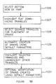
- drains are typically larger than vents (since a drain, unlike a vent, must be large enough to allow unsolidified material to flow), and are created on flat down-facing triangles as opposed to flat up-facing triangles. Therefore, only the differences between this process and the previously-described process of creating vents will be described.
- the process is illustrated in Figure 20.
- the first step, identified with numeral 1026 involves selecting a bottom view of the part using the "Vewing Transformation” window of Figure 25.
- the user selects the "Display Drain Triangles" button from the "Vents and Drains” window ( Figure 21).
- VIEW highlights the flat down-facing triangles using an appropriate color, i.e., yellow.
- the third step, identified with numeral 1028 the user selects from the set of flat down-facing triangles, the desired triangles for the placement of drains.
- VIEW highlights the selected triangles using an appropriate different color, i.e., white.
- the user prompts VIEW to automatically create the drains by clicking on the "Create” button in the "Vents and Drains” window.
- VIEW does so by creating the drains in the selected triangles using default parameters.
- the default shape, position, and size of a drain is a circle centered in the middle of the triangle having a radius of 3.750 mm (0.150 in.) for both the Cibatool SL 5170 (preferred for use with the SLA 190/250) and SL 5180 (preferred for use with the SLA 500).
- VIEW highlights the triangles selected for placement of drains and the drains themselves with an appropriate color, i.e., yellow, and unhighlights the other flat down-facing triangles.
- the user optionally repositions, changes the radius of, or deselects any of the drains using the "Vents and Drains" window. The result is one or more drains as depicted in Figures 43 and 44 (through identifying numerals 1033 and 1034).
- VIEW allows a user to change the default radius of the vents and drains and their positioning. It should be appreciated that the inclusion of additional commands are possible which provide for a default shape. It should also be appreciated that several other refinements and enhancements of this embodiment are possible, including, without limitation, the insertion of vents or drains on near-flat surfaces.
- VIEW allows a user to save the information descriptive of the drains and vents in a data file.
- the information saved by VIEW consists, for each vent or drain, the x, y, z coordinates of the center point of vent or drain, the x, y, z components (I, j, k) of the triangle normal, and the radius of the vent or drain.
- C-SLICE i.e., the Boolean layer comparison SLICE program described in U.S. Patent No. 5,321,622 (the '622 patent), along with the unaltered object representation.
- C-SLICE produces up to three types of borders in relation to an object layer, up-facing boundaries (UB), layer boundaries (LB), and down-facing boundaries (DB).
- C-SLICE manipulates it based on the information provided by VIEW. For a given drain or vent, C-SLICE determines which layer is required to be modified using the z-coordinate of the triangle in which the vent or drain appears (the singular term is used given that the triangles in this first embodiment are constrained to be flat triangles which, by definition, lie entirely within a given z-plane).
- the sign of the k-component of the triangle normal is then used to determine whether to modify the UB or DB information. If the sign is positive, indicative of a vent, the modification is made to the UB information; if negative, the modification is made to the DB information.
- the UB and DB information created by C-SLICE is preferably in the form of a polylist, i.e., an ordered sequence of line segments which circumscribe a solid or hollow feature of the object.
- the order of the coordinates obeys the right-hand rule.
- the segments are ordered in a counterclockwise direction if they define an exterior boundary of the object, i.e., circumscribe a solid portion of the object.
- the segments will be ordered in a clockwise direction.
- the technique involves describing the vent or drain with a polylist.
- a polylist of 255 segments is used, but it should be appreciated that other options are possible.
- the coordinates of the segments are ordered, in accordance with the right-hand rule, in a clockwise direction. That is because, by definition, they describe a hole.
- the sign of the k component of the triangle normal is then evaluated. If the sign is positive, the UB data is earmarked for modification; if the sign is negative, the DB data is earmarked for modification.
- a Boolean union operation as is described in the '622 patent, is then performed between the appropriate data, whether UB or DB, and the polylist describing the hole or vent in question.
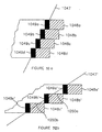
- the circle identified with numeral 1035 depicts a polylist which is representative of a border (whether up-facing or down-facing) enclosing solid area.
- the segments making up the polylist are ordered in a counter-clockwise direction.
- the circle identified with numeral 1036 depicts a polylist which represents a vent or drain.
- the segments making up the polylist are ordered in a clockwise direction since a vent or drain by definition encloses a hollow region.
- the Boolean union of the two polylists is identified with numeral 1037.
- An aspect of QUICKCAST is the creation of multiple layers of skinning of the object in order to create a strong shell for use in investment casting.
- the aforementioned step, in which the polylist making up a hole or vent is Boolean unioned with UB or DB data, must be repeated for each of these skinned layers. If it is only performed with less than all, the hole or vent will become skinned over, i.e., blocked, in the final part.
- this embodiment for automatic vent or drain creation can also be used to drain unsolidified material from trapped volumes within solid parts.
- trapped volumes can lead to leading and trailing edge problems due to the buildup of material during the recoating process.
- the problem can be significant: the buildup of material, once solidified, can interfere with the operation of the doctor blade or sweeper used to recoat.
- the selection of appropriate recoating parameters to at least partly eliminate these problems, as discussed in the previously-referenced U.S. Patent No. 5,258,146, is not an entirely satisfactory solution because it prevents the selection of recoating parameters which are independent of the geometry of the particular part at hand.
- Automatic vent or drain generation would help eliminate trapped volumes.
- the union operation is not only performed on down-facing or up-facing regions but on all regions (down-facing, up-facing and continuing) on all layers between the specified down-facing or up-facing feature and the opposite up-facing or down-facing feature inclusive.
- vents or drains fit within a single triangle, or even within a particular up-or down-facing region. If the vent or drain falls partially outside an up- or down-facing region the vent or drain will be reduced in size since part of it will be missing.
- polylist 1035 representing either an up-facing or down-facing border
- polylist 1036' which, as shown, encircles a hole which is not entirely encompassed by the polylist 1035.
- the result of this union operation is the boundary depicted in Figure 28. Since this boundary defines the limits to which hatch or skin will be created on the layer in question, a vent or drain, identified with numeral 1039, will still be created in the final part, albeit with a reduced surface area in relation to the hole described by polylist 1036'.
- the data provided by VIEW can be use din combination with an object representation formatted in accordance with the SLC format (a contour/layer format described in the '622 patent). Through Boolean union operations, such data can be modified using the vent/drain data provided by VIEW in the manner described.
- vents/drains in a three-dimensional object A second embodiment for automatically inserting vents/drains in a three-dimensional object will now be described.
- the capability is provided for introducing vents or drains in near-flat regions of the object, a capability which is especially useful in the case of parts which, through reorientation to eliminate trapped volumes, facilitate the creation of supports, and the like, have no flat regions.
- a first approach to implementing this second embodiment involves introducing a flat region into the object representation at the originally near flat region, and then applying the just-discussed embodiment to insert a drain or vent in the just-created flat region.
- the technique involves using VIEW to display the object, selecting from library of predetermined representations a representation of a second object having a flat surface (such as a cylinder or rectangular bar), situating in VIEW the second object representation such that the flat area is appropriately situated within the near-flat region of the first object representation, and then performing a Boolean differencing operation between the two representations.
- the previously-discussed embodiment is then used to insert a vent or drain at the resultant flat area created in the first object representation.
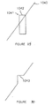
- Figure 29 is shown a near flat area, identified in the figure with numeral 1040, and a representation of a cylinder, identified with numeral 1041, having a flat area 1042 which has been situated within the near flat area.
- a flat region, identified with numeral 1043 is created within the part for insertion of vents or drains.
- a variant of this technique involves performing this Boolean operation in the CAD system, i.e., modifying an .STL file representing the object.
- a second approach to implementing this second embodiment involves a modification to C-SLICE, the Boolean layer comparison "slice" "program described in the '622 patent
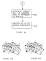
- a flowchart of the technique is illustrated in Figure 31a.
- the first step identified with numeral 1044, involves taking as input the preliminary boundary data described in the '622 patent (used as input to the Boolean layer comparison operations which results in the formation of the UB, LB, and DB data), i.e., the L[i] data, and performing a Boolean differencing between this data and data descriptive of desired vent and drain zones. The effect is to create a flat region for the insertion of a vent/drain.
- This step is illustrated in Figure 31 b.
- the preliminary boundary data for a layer identified with numeral 1057, which is moved/retracted to position 1057, through this Boolean differencing operating. The effect is to create flat region 1058.
- the modified L[i] data is processed through C-SLICE in the traditional way to arrive at UB, LB, and DB data reflecting the inclusion of the vent and drain zones.
- the resultant UB and DB data is modified through a second pass with the data descriptive of the vents and drains in the manner described previously in relation to the first embodiment, i.e.
- a potential problem with these approaches involves the possible formation of relatively large indentations in the object due to the need to create a large enough flat region in order to insert a drain or vent of acceptable size.
- the slope of the slanted surface becomes steeper it is clear that the indentation becomes larger for a given size of the flat feature to be created.
- the indentations thus formed may represent an unacceptable distortion of the object surface.
- An additional potential problem with these approaches arises from the fact that the hole inserted is not located at the lowest extreme of the object feature into which it is inserted. If the hole is to act as a drain, it is apparent that not all of the internal liquid can be drained from the object unless the object is tilted. Of course, if an automatic object tiling feature is added to the platform support structure to which the object is attached, this becomes a non-issue.
- a third approach to implementing this second embodiment simply involves removing the skins associated with a sloped surface and leaving the layer boundaries in place.
- the defined hole would have a slanted orientation wherein portions of the hole would be associated with successive layers.
- the partial hole associated with the successive layers or cross-sections of data can be obtained by projecting the portion of the slanted hole in between two cross-sections onto the appropriate of the two cross-sections (typically the upper portion of the layer or upper cross-section). Techniques for performing the projection operation are described in previously referenced U.S. Patents 5,345,391 and 5,321,622.
- FIG 32a for example, a steep near-flat surface (identified with numeral 1047) is shown.
- the LB regions associated with the respective layers are identified with numerals 1049a, 1049b, 1049c, and 1049d, and the DB regions associated with the respective layers are identified with numerals 1048a, 1048b, 1048c, and 1048d.
- the removal of the DB regions, which the above-described variant will accomplish, will leave no gap in the resultant surface of the object. That is because the surface is so steep, that the LB regions from successive layers are close enough to one another to close any gaps.
- a fourth approach for implementing this second embodiment will now be described.
- An advantageous aspect of this approach is that it can be used to insert vents/drains in vertical as well as near-flat regions.
- a new boundary type is created known as the "anti-boundary."
- a requirement imposed by C-SLICE is that layer boundaries (LB) form closed loops. The requirement is imposed because of the function performed by layer boundaries: they are used to generate hatch and fill vectors. As illustrated in Figure 33, if a break 1052 were to appear in the layer boundary 1051 of an object, it would lead to the creation of unwanted hatch or fill (identified with numeral 1053).
- Temporary boundaries define the portion of layer boundaries which are not to be solidified. Temporary boundaries complement regular boundaries so a complete closed loop is formed. These temporary boundaries are retained for use in generating hatch/fill vectors but are not included with the boundaries to be exposed.
- FIG. 34a-34b An approach for generating temporary boundaries, illustrated in Figures 34a-34b, is from the intersection between the desired vent/drain (as it exists on the near-flat/vertical surface of the object) (identified in the figures with numeral 1054) and the slicing planes (identified in Figure 22a with numerals 1055a, 1055b, 1055c, 1055d, 1055e, and 1055f) used in C-SLICE (layer comparison slice).
- the result is a series of lines (partial boundaries) at various z-positions, identified in Figure 34b with numerals 1056a, 1056b, 1056c, 1056d, and 1056e, which constitute the temporary boundaries.
- two boundaries can be formed, wherein one boundary includes a purposely designed break in it and is used for exposing the material.
- the other boundary forms a complete loop and is used for hatch or fill generation.
- a complete boundary loop can be generated along with one or more "anti-boundary" segments.
- the complete boundary loop is used for generating hatch after which a Boolean difference is taken between the boundary loop and the anti-boundary segment to yield an incomplete or broken boundary to be utilized in exposing the material.
- An .STL representation of an object may be converted into a new representation known as the .CTL file format (the term "CTL” stands for Compressed Triangle List), and then using the resulting .CTL file in the remaining stereolithographic process steps.
- CTL Compressed Triangle List
- the technique involves eliminating redundant vertices, and then expressing triangles which substantially span the surface or surfaces of the object in terms of identifiers of the non-redundant vertices.
- each .STL triangle is first compared to a list, and then added thereto if not already present in the list.
- each .STL triangle is preferably represented by nine floating point numbers which define the Cartesian coordinates of the three triangle vertices, as well as three floating point numbers which define the Cartesian coordinates of the triangle normal.
- the order in which the vertices are listed preferably obeys the "right-hand rule,” according to which the backside of the triangle is taken to surface a solid if they are oriented in a counter-clockwise direction, and are taken to surface a hollow region if they are oriented in a clockwise direction.
- the three floating point numbers are each compared with the corresponding numbers making up each vertex in the list, In performing the comparisons, strict identity is not required. Instead, a "delta" value is used to take account of the rounding error associated with floating point numbers. The value represents a zone by which two floating point numbers can differ and still be considered identical.
- Figure 7 illustrates two triangles, identified with numerals 654 and 655.
- the first triangle identified with numeral 654, is assumed to have the following vertices: (0.00001, 0.0, 0.0), (0.0, 1.0, 1.0), and (0.0, 0.0, 1.0).
- the second triangle, identified with numeral 655 is assumed to have the following vertices: (0.0, 0.0, 0.0001), (1.0, 0.0, 0.0), and (0.0, 1.0, 1.0).
- the vertices of triangle 654 are then evaluated for placement on the list Since the list is presently empty, each vertex of triangle 654 is placed on the list.
- the vertices of triangle 655 are then evaluated for placement on the list. Assuming a delta of .001 is used, this evaluation results in a determination that the first and third vertices (0.0, 0.0, 0.0001) and (0.0, 1.0, 1.0) are already in the list, having been placed there in connection with triangle 654 while the third vertex is new. Thus, the net result of this evaluation process is the placement of the second (1.0, 0.0, 0.0) vertex in the list.
- the list of vertices is as follows:- (0.00001, 0.0, 0.0), (0.0, 1.0, 1.0), (0.0, 0.0, 1.0), and (1.0, 0.0, 0.0).
- any vertex added to the list is represented with a unique integer.
- the integer represents the position or index of the vertex in the list.
- V0 (0.00001, 0.0, 0.0)
- V1 (0.0, 1.0, 1.0)
- V2 (0.0, 0.0, 1.0)
- V3 (1.0, 0.0, 0.0).
- each triangle is represented by the three integers which define the vertices of the triangle.
- the two triangles illustrated in Figure 7 might be represented as follows: T1 (identified with numeral 654 in Figure 7): (0, 1, 2), and T2 (identified with numeral 655 in Figure 7): (0, 3, 1).
- an array of Boolean flags is established, one for each vertex in the list.
- the purpose of the flags is to keep track of which vertices have been moved. Initially, each flag is cleared.
- the flags of all vertices of down-facing triangles are set to a logical "1".
- the down-facing triangles are identified using the Z-component of the triangle normals. In the case of down-facing triangles, such value is negative and will be equal to -1.
- the Z components of the vertices whose flags have been set may be adjusted to correct for Z-error.
- the MSD is 12 mils (0.3 mm) and the desired layer thickness is 4 mils (0.1 mm)
- the Z-components of the vertices of the down-facing triangles would be adjusted upwards by 8 mils (0.2 mm).
- the modified .CTL file which results from this process is then used in lieu of the .STL representation in the remaining steps of the stereolithographic building process.
- that process will have to be modified slightly in order to accommodate the new .CTL format, such modifications are simple to make, and believed to be within the skill of the ordinary practitioner. For example, one could plug actual values in for the identifiers as each vertex is processed. Thus, they will not be further described.
- an advantage of this embodiment over the second is computational efficiency resulting from a reduction in the number of vertices which must be moved.
- it is necessary to move the vertices of the down-facing triangles as well as all vertices which touch or are within a specified rounding error from one another.
- the third embodiment by contrast, only the vertices of the down-facing triangles need be moved.
- the vertices of the other triangles are automatically adjusted because of the manner in which they are represented (i.e., through integers which uniquely identify the vertices making up the triangles).
- the step of adjusting the Z-components of the vertices of the down-facing triangles automatically adjusts all relevant triangles.
- Another advantage relates to a reduction in storage requirements.
- the floating point numbers making up the vertices need only be stored once.
- the redundancy of vertices amongst triangles results in multiple copies of the same vertex being stored.
- the technique involves selection of an appropriate hash function which is effective for the purposes of putting similar vertices, i.e., vertices within a specified rounding error, into the same buckets of the hash table, while simultaneously achieving a wide disparity between dissimilar vertices.
- the technique involves sorting the triangle vertices to a hash table, and eliminating redundant vertices by comparing the vertices which fall within the same bucket or slot of the hash table.
- the non-redundant vertices are then labeled with unique identifying indicia, and the triangles are then expresses in terms of the unique identifying indicia rather than the vertices themselves.
- modulus (integer(abs((x*31.3 + y*24343.0 + z*68.265))), where the term “modulus” refers to the modulus function (i.e., the modulus of a number is the integer remainder, remaining after dividing the number by the base), the term “abs” refers to the absolute value function, the term “integer” refers to the integerization function, the base of the modulus function is the size of the hash table, and x, y, and z refer to the intergized Cartesian coordinates of the vertex in question.
- the first step involves, for a given triangle, hashing the triangle vertices into a bucket of the hash table by applying the hash function to the coordinates of each vertex.
- the vertex is compared with any vertices already stored in the bucket. If there is a "match,” i.e., if the coordinates of the two are determined to be within a specified delta value of one another (and thus redundant), then the vertex is not retained in the table.
- the step identified with numeral 663 in the figure the integer associated with the entry already stored in the table is taken for use in representing the given triangle.
- step identified with numeral 664 if there is no match, indicating that the vertex is not redundant, in the step identified with numeral 664, then the vertex is stored in the bucket, and a unique identifying integer is assigned to the vertex.
- the step identified with numeral 665 the given triangle is represented by the integer used to represent its vertex. This process is then repeated for the remaining vertices in the object representation. After all the triangles have been represented, as illustrated by the step identified with numeral 666, the technique proceeds as discussed in relation to the second embodiment.
- a user may want to display the object, prior to slicing or building it, in order to orient it properly and the like
- Figures 10a-10b The technique is illustrated in Figures 10a-10b.
- the dashed lines illustrate the zones delineated by the large delta chosen. All vertices within a given zone will collapse into a single vertex.
- Figure 10a illustrates the individual vertices prior to their being collapsed.
- Figure 10b illustrates the number of points (emphasized in the figure) into which some of these individual vertices will collapse.
- FIG. 30a shows the points into which the vertices will collapse
- Figure 30b shows the number of distinct vertices which will remain with each triangle. As can be seen, only a very few of the triangles illustrated will remain non-degenerate, i.e., retain three distinct vertices.
- FIGs 32a-32b The expansion of the remaining non-degenerate triangles to cover the resultant space is illustrated in Figures 32a-32b.
- the set of non-degenerate triangles, prior to expansion, is illustrated in Figure 32a. Note that one vertex from one of these triangles is contained in each one of the zones delineated by the delta value. When these vertexes are respectively collapsed into the single points within the respective zones, the effect is to expand the size of the non-degenerate triangles and fill the space left by the removal of the degenerate triangles. This process is illustrated in Figure 32b.
- delta square root (area/desired number of triangles).
- a second additional application of the .CTL representation is the building of a hollow shell of an object.
- a flowchart of a technique for doing so is illustrated in Figure 14.
- a normal of a vertex is computed by averaging the coordinates of the normals of all triangles the vertex is common to or touches upon.
- the average can be computed as a simple arithmetic average, but is preferably a weighted average, with the weights being determined by the relative areas of the respective triangles, or more preferably by the relative sizes of the angles making up the respective triangle vertices.
- the method of weighting by angle size is illustrated in Figure 15.
- the .CTL representation of the object is copied, and then expanded by moving the vertices in the directions called for by the respective vertex normals.
- the expansion is accomplished simply by manipulating the list of vertices.
- the triangles which are represented by groupings of integers representing the triangle vertices, need not be altered at all.
- the degree of expansion depends on the desired thickness of the shell. The level of expansion should be such that the difference between the outer surface of the expanded representation and the original surface is equal to the desired thickness.
- the triangles making up the original .CTL representation are effectively "flipped" to create a representation of the inner surface of the shell. This is accomplished by switching the sign of the triangle normals, and also possibly by changing the order of the vertices to reflect the right-hand rule.
- the expanded file and the original file are merged to produce a .CTL representation of a hollow shell.
- This .CTL file is then used to drive the remaining steps of the stereolithographic process, beginning with the slicing process.
- a copy of the .CTL file can be made and the vertex normals determined.
- the vertex normals can be reversed in the copy.
- the vertices of the copy can be shifted in the direction of the reversed normals to yield a contracted size.
- original step 4 (670 of Figure 14) the original and shifted .CTL files are merged to produce a hollow shell.
- This alternative embodiment is considered most preferred since it leaves the outer dimension of the object as in the original file. However, if the inner dimension of the object is considered most relevant the embodiment of Figure 14 would be considered more preferable.
- the above embodiment for forming a shell can be used to form a solid object wherein two or more different building styles can be sued at different depths into the object.
- a copy of the shifted representation can be made and the normals can be reversed back to their original directions to form a third representation.
- This third representation represents an internal region of the object while the combined first and second representations represent an outer shell region (exterior region) of the object.
- Different build parameters e.g. bordering, hatching, and filling patterns, solidification amounts
- additional copies, offsetting, and normal reversals can be performed to yield additional zones or regions as one moves deeper into the object.
- the offset or shifting amount can vary from level to level.
- a third additional application of the .CTL representation is the building of a scaled-down part which, upon being powder coated or the like (described in U.S. Patent No. 5,234,636), will be at the correct size.
- a technique for producing a .CTL file for such a part involves computing the vertex normals, as described previously, and then moving the vertices in the direction opposite to that specified by the normals until an object representation having the correct scaled down dimensions is created.
Claims (41)
- Verfahren zum Bereitstellen eines dreidimensionalen Objekts, das schichtweise durch die gezielte Verfestigung eines verfestigbaren Mediums aufgebaut werden soll, bei dem zumindest ein Bereich des Objekts, der in einem ersten Datensatz, der das Objekt definiert, als fest angegeben ist, gemäß einem zweiten Datensatz aufgebaut wird, der als eine Struktur mit Zwischenräumen vom ersten Datensatz abgeleitet ist, die nicht verfestigtes Medium zwischen verfestigten Strukturelementen enthalten, wobei der zweite Datensatz vorsieht, dass das Objekt mit einer oder mehreren Oberflächen aufgebaut wird, die den Bereich definieren, und die die Zwischenräume gegenüber der Außenseite des Objekts abdichten, wobei zumindest eine der Oberflächen eine Entlüftungsöffnung oder eine Sickerbohrung (1032, 1033, 1034) aufweist, die das Entleeren von nicht verfestigtem Medium aus den Zwischenräumen ermöglicht.
- Verfahren nach Anspruch 1, wobei die zumindest eine Oberfläche eine flache Oberfläche ist.
- Verfahren nach Anspruch 1, wobei die zumindest eine Oberfläche eine nahezu flache Oberfläche ist.
- Verfahren nach einem der vorangegangenen Ansprüche, in der die Oberfläche eine vertikale Oberfläche ist.
- Verfahren nach einem der vorangegangenen Ansprüche, in der der erste Datensatz die Form des Objekts in der Form von Polygonen definiert, die durch ihre Ecken definiert werden und wobei die Entlüftungsöffnung oder Sickerbohrung (1032, 1033, 1034) durch die Auswahl unter den Oberflächen, die vom ersten Datensatz definiert werden, und durch das Modifizieren des zweiten Datensatzes erhalten wird, um die Entlüftungsöffnung oder die Sickerbohrung (1032, 1033, 1034) in die zumindest eine Oberfläche mit aufzunehmen.
- Verfahren nach einem der Ansprüche 1-4, wobei der erste Datensatz die Form des Objekts in der Form von Polygonen definiert, die durch ihre Ecken definiert werden, und wobei die Entlüftungsöffnung oder Sickerbohrung (1032, 1033, 1034) durch die Auswahl unter den Polygonen, die durch den ersten Datensatz definiert werden und durch das Modifizieren des zweiten Datensatzes erhalten wird, um die Entlüftungsöffnung oder Sickerbohrung 1032, 1033, 1034) in zumindest ein ausgewähltes Polygon mit aufzunehmen.
- Verfahren nach Anspruch 6, wobei das zumindest eine ausgewählte Polygon im wesentlichen flach ist.
- Verfahren nach einem der Ansprüche 1 - 4, wobei der erste Datensatz das Objekt als eine Mehrzahl von Darstellungen der Grenzen von Querschnitten des Objekts definiert, wobei die Entlüftungsöffnung oder Sickerbohrung (1032, 1033, 1034) durch das Modifizieren von zumindest einer Grenzendarstellung des zweiten Datensatzes erhalten wird, um die Entlüftungsöffnung oder Sickerbohrung (1032, 1033, 1034) in die Grenze mit aufzunehmen.
- Verfahren nach einem der vorangegangenen Ansprüche, ferner aufweisend: Speichern von Datensätzen, die die Entlüftungsöffnungen bzw. Sickerbohrungen (1032, 1033, 1034) definieren und bei denen die Aufnahme einer Entlüftungsöffnung oder einer Sickerbohrung (1032, 1033, 1034) in die zumindest eine Oberfläche das Kombinieren eines gespeicherten Datensatzes, der ein Entlüftungsloch oder eine Sickerbohrung definiert (1032, 1033, 1034), mit Daten vom ersten Datensatz, die sich auf die Oberfläche beziehen, in der die Entlüftungsöffnung oder Sickerbohrung (1032, 1033, 1034) bereitgestellt werden soll, umfasst.
- Verfahren nach Anspruch 9, wobei das Kombinieren eines gespeicherten Datensatzes mit Daten aus den ersten Daten eine Boolesche Verknüpfung umfasst.
- Verfahren nach Anspruch 10, wobei die Boolesche Verknüpfung eine Boolesche Multiplikation ist.
- Verfahren nach Anspruch 9 - 11 bei dem die oder zumindest eine Oberfläche aus mehreren Schichten von mehreren Lagen einer Außenschicht aufgebaut wird und wobei das Kombinieren auf jede der mehreren Lagen der Außenschicht angewendet wird.
- Verfahren nach einem der vorangegangenen Ansprüche, bei dem eine weitere Objektdarstellung (1041) mit zumindest einer vertikalen Oberfläche und einer flachen Oberfläche (1042) ausgewählt wird, wobei die weitere Objektdarstellung (1042) so in Bezug auf die erste genannte Objektdarstellung orientiert ist, dass die flache Oberfläche und/oder die vertikale Oberfläche (1042) der weiteren Objektdarstellung nahe einer nahezu flachen Oberfläche der ersten genannten Objektdarstellung angeordnet ist, eine Boolesche Verknüpfung zwischen den Objektdarstellungen durchgeführt wird, um eine modifizierte Objektdarstellung mit einer flachen Oberfläche oder einer vertikalen Oberfläche (1043) zu bilden, die an der nahezu flachen Oberfläche der Objektdarstellung gebildet wird, und bei dem die Sickerbohrung oder Entlüftungsöffnung (1032, 1033, 1034) in die flache oder vertikale Oberfläche (1043) der modifizierten Objektdarstellung eingefügt wird.
- Verfahren nach einem der vorangegangenen Ansprüche, in der die Entlüftungsöffnung oder Sickerbohrung (1032, 1033, 1034) durch einen Ort und eine Dimension spezifiziert wird.
- Verfahren nach Anspruch 14, in der die Dimension der Entlüftungsöffnung oder Sickerbohrung (1032, 1033, 1034) aus einer oder mehreren voreingestellten Dimensionen ausgewählt wird.
- Verfahren nach einem der vorangegangenen Ansprüche, in der die Dimension eine Sickerbohrung (1033, 1034) mit einem nach unten gerichteten Bereich größer ist als die Dimension einer Entlüftungsöffnung (1032) in einem nach oben gerichteten Bereich.
- Verfahren nach einem der vorangegangenen Ansprüche, bei dem das verfestigbare Material eine fotopolymerisierbare Flüssigkeit ist.
- Verfahren nach einem der vorangegangenen Ansprüche, bei dem die Schichten selektiv einer synergistischen Stimulation gemäß der Daten ausgesetzt werden.
- Verfahren nach Anspruch 18, in der die synergistische Stimulation ultraviolette Strahlung umfasst.
- Verfahren nach einem der vorangegangenen Ansprüche, in der jegliches nicht verfestigtes Material innerhalb des Objektes zumindest teilweise, nachdem das Objekt gebildet worden ist, von dem Objekt entfernt wird, durch die zumindest eine Sickerbohrung (1033, 1034).
- Verfahren zum Genauguss, bei dem ein Objekt, das nach Anspruch 20 gebildet worden ist, als Gussmodell verwendet wird.
- Vorrichtung zum Bereitstellen eines dreidimensionalen Objektes, das schichtweise durch die gezielte Verfestigung eines verfestigbaren Mediums aufgebaut werden soll, in der zumindest ein Bereich des Objekts, der in einem ersten Datensatz, der das Objekt definiert, als fest angegeben ist, gemäß einem zweiten Datensatz, der vom ersten Datensatz abgeleitet worden ist, als eine Struktur mit Zwischenräumen aufgebaut wird, die nicht verfestigtes Medium zwischen verfestigten Strukturelementen enthalten, wobei die Vorrichtung ein Erzeugungsmittel für den zweiten Datensatz umfasst, um den zweiten Datensatz mit einer oder mehrere Oberflächen zu erzeugen, die den Bereich definieren und die die Zwischenräume gegenüber der Außenseite des Körpers abdichten, wobei ein eine Entlüftungsöffnung oder eine Sickerbohrung bildendes Mittel bereitgestellt wird, um zumindest auf einer der Oberflächen eine Entlüftungsöffnung oder eine Sickerbohrung (1032, 1033, 1034) bereitzustellen, die die Entleerung von nicht verfestigtem Medium aus den Zwischenräumen ermöglicht.
- Vorrichtung nach Anspruch 22, wobei die zumindest eine Oberfläche eine flache Oberfläche ist.
- Vorrichtung nach Anspruch 22, wobei die zumindest eine Oberfläche eine nahezu flache Oberfläche ist.
- Vorrichtung nach einem der Ansprüche 22 - 24, in der die Oberfläche eine vertikale Oberfläche ist.
- Vorrichtung nach einem der Ansprüche 22 - 25, in der der erste Datensatz die Form des Objektes in der Form von Polygonen definiert, die durch ihre Ecken definiert werden und wobei das Mittel zum Bilden der Entlüftungsöffnung oder der Sickerbohrung ( 1032, 1033, 1034) unter den Oberflächen, die durch den ersten Datensatz definiert werden, auswählt und den zweiten Datensatz modifiziert, um die Entlüftungsöffnung oder die Sickerbohrung (1032, 1033, 1034) in der zumindest einen Oberfläche aufzunehmen.
- Vorrichtung nach einem der Ansprüche 22- 25, in der der erste Datensatz die Form des Objektes in der Form von Polygonen definiert, die durch ihre Ecken definiert werden, und wobei das Mittel zum Bilden der Entlüftungsöffnung oder Sickerbohrung (1032, 1033, 1034) unter den durch den ersten Datensatz definierten Polygonen auswählt und den zweiten Datensatz modifiziert, um die Entlüftungsöffnung oder Sickerbohrung (1032, 1033, 1034) in dem zumindest einen ausgewählten Polygon aufzunehmen.
- Vorrichtung nach Anspruch 26, in der das zumindest eine ausgewählte Polygon im wesentlichen flach ist.
- Vorrichtung nach einem der Ansprüche 22- 25, in der der erste Datensatz das Objekt als eine Mehrzahl von Darstellungen von Grenzen der Querschnitte des Objekts definiert und wobei das Mittel zum Bilden der Entlüftungsöffnung oder Sickerbohrung (1032, 1033, 1034) zumindest eine der Grenzendarstellungen des zweiten Datensatzes modifiziert, um die Entlüftungsöffnung oder die Sickerbohrung in die Grenze aufzunehmen.
- Vorrichtung nach einem der Ansprüche 22- 29 ferner aufweisend ein Mittel zum Speichern von Datensätzen, die Entlüftungsöffnungen und Sickerbohrungen definieren (1032, 1033, 1034) und wobei das Mittel zum Bilden von Entlüftungsöffnungen oder Sickerbohrungen ein Mittel zum Kombinieren eines gespeicherten Datensatzes umfasst, der eine Entlüftungsöffnung oder eine Sickerbohrung (1032, 1033, 1034) definiert, mit Daten aus dem ersten Datensatz, die sich auf die Oberfläche beziehen, in der die Entlüftungsöffnung oder Sickerbohrung (1032, 1033, 1034) bereitgestellt werden soll.
- Vorrichtung nach Anspruch 30, in der das Mittel zum Kombinieren des gespeicherten Datensatzes mit den Daten aus den ersten Daten ein Mittel zum Durchführen einer Booleschen Verknüpfung umfasst.
- Vorrichtung nach Anspruch 31, in der die Boolesche Verknüpfung eine Boolesche Multiplikation ist.
- Vorrichtung nach einem der Ansprüche 30 - 32, in der zumindest eine Oberfläche aus mehreren Lagen von Außenschichten aufgebaut wird und wobei das Mittel zum Kombinieren vorgesehen ist, um die Daten von jeder der mehreren Lagen der Außenschicht zu kombinieren.
- Vorrichtung nach einem der Ansprüche 22 - 33, in der ein Mittel bereitgestellt wird, um eine weitere Objektdarstellung (1041) auszuwählen, die zumindest eine vertikale Oberfläche und eine flache Oberfläche (1042) hat und zum Orientieren der weiteren Objektdarstellung (1041) in Bezug auf die erste genannte Objektdarstellung (1041), so dass die flache Oberfläche (1042) und/oder die vertikale Oberfläche der weiteren Objektdarstellung (1041) nahe einer nahezu flachen Oberfläche der ersten genannten Objektdarstellung angeordnet ist,
ein Mittel zum Durchführen einer Booleschen Verknüpfung zwischen den Objektdarstellungen, um eine modifizierte ersten Darstellung des Objekts zu bilden, die eine flache Oberfläche oder eine vertikale Oberfläche (1043) umfasst, die an der nahezu flachen Oberfläche der ersten Objektdarstellung gebildet wird und in der das Mittel zum Bilden der Sickerbohrung oder Entlüftungsöffnung (1032, 1033, 1034) die Sickerbohrung oder Entlüftungsöffnung (1032, 1033, 1034) in der flachen oder vertikalen Oberfläche der modifizierten Objektdarstellung bildet. - Vorrichtung nach einem der Ansprüche 22- 34, in der die Vorrichtung die Entlüftungsöffnungen oder Sickerbohrung (1032, 1033, 1034) durch einen Ort und eine Dimension spezifiziert.
- Vorrichtung nach Anspruch 35, ferner aufweisend: einen Speicher zum Speichern von einer von mehreren voreingestellter Dimensionen für eine Entlüftungsöffnung oder eine Sickerbohrung (1032, 1033, 1034) und die ein Mittel umfasst, zur Auswahl der Dimension der Entlüftungsöffnung oder Sickerbohrung (1032, 1033, 1043) aus der einen oder der mehreren voreingestellten Dimensionen.
- Vorrichtung nach einem der Ansprüche 22 - 36, in der das Mittel zum Bilden der Entlüftungsöffnung oder Sickerbohrung (1033, 1034) eine Sickerbohrung in einem nach unten gerichteten Bereich mit einer größeren Dimension bildet, als die Dimension einer Entlüftungsöffnung (1032) in einem nach oben gerichteten Bereich.
- Vorrichtung nach einem der Ansprüche 22 - 37, bei der das verfestigbare Material eine fotopolymerisierbare Flüssigkeit ist.
- Vorrichtung nach einem der Ansprüche 22 - 38, ferner aufweisend eine Quelle zur synergistischen Stimulation, in der die Schichten selektiv der synergistischen Stimulation gemäß der Daten ausgesetzt werden.
- Vorrichtung nach Anspruch 39, in der die Quelle der synergistischen Stimulation eine Quelle von ultravioletter Strahlung umfasst.
- Vorrichtung nach einem der Ansprüche 22 - 40, zum Bereitstellen einer Entlüftungsöffnung oder einer Sickerbohrung (1032, 1033, 1034) in einem dreidimensionalen Objekt nach dem Verfahren einer der Ansprüche 1-20.
Priority Applications (1)
| Application Number | Priority Date | Filing Date | Title |
|---|---|---|---|
| EP01201196A EP1120227A3 (de) | 1994-04-25 | 1995-04-25 | Fortschrittliche Bautechniken in Stereolithografie |
Applications Claiming Priority (5)
| Application Number | Priority Date | Filing Date | Title |
|---|---|---|---|
| US23302694A | 1994-04-25 | 1994-04-25 | |
| US233027 | 1994-04-25 | ||
| US08/233,027 US5597520A (en) | 1990-10-30 | 1994-04-25 | Simultaneous multiple layer curing in stereolithography |
| US233026 | 1994-04-25 | ||
| PCT/US1995/005148 WO1995029053A2 (en) | 1994-04-25 | 1995-04-25 | Enhanced building techniques in stereolithography |
Related Child Applications (1)
| Application Number | Title | Priority Date | Filing Date |
|---|---|---|---|
| EP01201196A Division EP1120227A3 (de) | 1994-04-25 | 1995-04-25 | Fortschrittliche Bautechniken in Stereolithografie |
Publications (2)
| Publication Number | Publication Date |
|---|---|
| EP0757621A1 EP0757621A1 (de) | 1997-02-12 |
| EP0757621B1 true EP0757621B1 (de) | 2001-11-21 |
Family
ID=26926564
Family Applications (2)
| Application Number | Title | Priority Date | Filing Date |
|---|---|---|---|
| EP95917693A Expired - Lifetime EP0757621B1 (de) | 1994-04-25 | 1995-04-25 | Fortschrittliche bautechniken in stereolithografie |
| EP01201196A Withdrawn EP1120227A3 (de) | 1994-04-25 | 1995-04-25 | Fortschrittliche Bautechniken in Stereolithografie |
Family Applications After (1)
| Application Number | Title | Priority Date | Filing Date |
|---|---|---|---|
| EP01201196A Withdrawn EP1120227A3 (de) | 1994-04-25 | 1995-04-25 | Fortschrittliche Bautechniken in Stereolithografie |
Country Status (7)
| Country | Link |
|---|---|
| EP (2) | EP0757621B1 (de) |
| JP (3) | JPH09512220A (de) |
| AT (1) | ATE209101T1 (de) |
| AU (1) | AU2365595A (de) |
| CA (1) | CA2186613A1 (de) |
| DE (1) | DE69524080T2 (de) |
| WO (1) | WO1995029053A2 (de) |
Cited By (1)
| Publication number | Priority date | Publication date | Assignee | Title |
|---|---|---|---|---|
| WO2020208064A1 (en) | 2019-04-09 | 2020-10-15 | Dentsply Sirona Inc. | Method of preventing fluid collection / suction in additive manufacturing of 3d objects |
Families Citing this family (16)
| Publication number | Priority date | Publication date | Assignee | Title |
|---|---|---|---|---|
| US5855718A (en) * | 1996-10-07 | 1999-01-05 | 3D Systems, Inc. | Method of and apparatus for making partially solidified three-dimensional objects on a layer-by-layer basis from a solidifiable medium |
| US6001297A (en) * | 1997-04-28 | 1999-12-14 | 3D Systems, Inc. | Method for controlling exposure of a solidfiable medium using a pulsed radiation source in building a three-dimensional object using stereolithography |
| US6084980A (en) * | 1997-05-13 | 2000-07-04 | 3D Systems, Inc. | Method of and apparatus for deriving data intermediate to cross-sectional data descriptive of a three-dimensional object |
| US5945058A (en) * | 1997-05-13 | 1999-08-31 | 3D Systems, Inc. | Method and apparatus for identifying surface features associated with selected lamina of a three-dimensional object being stereolithographically formed |
| US6159411A (en) * | 1999-02-08 | 2000-12-12 | 3D Systems, Inc. | Rapid prototyping method and apparatus with simplified build preparation for production of three dimensional objects |
| US6399010B1 (en) | 1999-02-08 | 2002-06-04 | 3D Systems, Inc. | Method and apparatus for stereolithographically forming three dimensional objects with reduced distortion |
| US6261077B1 (en) | 1999-02-08 | 2001-07-17 | 3D Systems, Inc. | Rapid prototyping apparatus with enhanced thermal and/or vibrational stability for production of three dimensional objects |
| US6574523B1 (en) * | 2000-05-05 | 2003-06-03 | 3D Systems, Inc. | Selective control of mechanical properties in stereolithographic build style configuration |
| US7497977B2 (en) * | 2003-01-29 | 2009-03-03 | Hewlett-Packard Development Company, L.P. | Methods and systems for producing an object through solid freeform fabrication by varying a concentration of ejected material applied to an object layer |
| JP2009132127A (ja) * | 2007-12-03 | 2009-06-18 | Sony Corp | 光造形装置および光造形方法 |
| EP3158399B1 (de) * | 2014-06-23 | 2022-10-26 | Carbon, Inc. | Polyurethanharze mit mehreren mechanismen zum härten zur verwendung bei der herstellung dreidimensionaler objekte |
| WO2016055386A1 (en) * | 2014-10-07 | 2016-04-14 | Materialise N.V. | System and method for recoating in an additive manufacturing environment |
| EP3234922A4 (de) | 2015-04-21 | 2018-12-05 | Hewlett-Packard Development Company, L.P. | Achterbaumserialisierung |
| JP6565495B2 (ja) * | 2015-08-28 | 2019-08-28 | 大日本印刷株式会社 | 立体物造形用データ分離装置 |
| JP6660817B2 (ja) * | 2016-06-10 | 2020-03-11 | 株式会社ミマキエンジニアリング | 立体物造形方法 |
| US10201940B2 (en) | 2015-11-12 | 2019-02-12 | The Boeing Company | Apparatus and method to predetermine a mechanical property of a three-dimensional object built by additive manufacturing |
Family Cites Families (12)
| Publication number | Priority date | Publication date | Assignee | Title |
|---|---|---|---|---|
| ATE113746T1 (de) * | 1986-06-03 | 1994-11-15 | Cubital Ltd | Gerät zur entwicklung dreidimensionaler modelle. |
| US4999789A (en) * | 1987-02-05 | 1991-03-12 | Hewlett-Packard Co. | Method and apparatus for trimming B-spline descriptions of patches in a high performance three dimensional graphics system |
| US4785399A (en) * | 1987-03-03 | 1988-11-15 | International Business Machines Corporation | Shaping geometric objects by cumulative translational sweeps |
| US5121333A (en) * | 1989-06-09 | 1992-06-09 | Regents Of The University Of Minnesota | Method and apparatus for manipulating computer-based representations of objects of complex and unique geometry |
| JPH0776991B2 (ja) * | 1989-10-24 | 1995-08-16 | インターナショナル・ビジネス・マシーンズ・コーポレーション | Nurbsデータ変換方法及び装置 |
| US5182715A (en) * | 1989-10-27 | 1993-01-26 | 3D Systems, Inc. | Rapid and accurate production of stereolighographic parts |
| WO1991012120A1 (en) * | 1990-02-15 | 1991-08-22 | 3D Systems, Inc. | Method of and apparatus for forming a solid three-dimensional article from a liquid medium |
| JPH0773884B2 (ja) * | 1990-05-02 | 1995-08-09 | 三菱商事株式会社 | 光固化造形装置 |
| JP2804829B2 (ja) * | 1990-06-27 | 1998-09-30 | 株式会社日立製作所 | 曲面加工方法 |
| ATE222848T1 (de) * | 1990-10-30 | 2002-09-15 | 3D Systems Inc | Schichtenvergleichstechniken in der stereolithographie |
| US5278949A (en) * | 1991-03-12 | 1994-01-11 | Hewlett-Packard Company | Polygon renderer which determines the coordinates of polygon edges to sub-pixel resolution in the X,Y and Z coordinates directions |
| JPH06114948A (ja) * | 1992-10-01 | 1994-04-26 | Shiimetsuto Kk | 未硬化液排出口付光硬化造形物とその造形法 |
-
1995
- 1995-04-25 CA CA002186613A patent/CA2186613A1/en not_active Abandoned
- 1995-04-25 JP JP7527841A patent/JPH09512220A/ja active Pending
- 1995-04-25 AU AU23655/95A patent/AU2365595A/en not_active Abandoned
- 1995-04-25 EP EP95917693A patent/EP0757621B1/de not_active Expired - Lifetime
- 1995-04-25 WO PCT/US1995/005148 patent/WO1995029053A2/en active IP Right Grant
- 1995-04-25 AT AT95917693T patent/ATE209101T1/de not_active IP Right Cessation
- 1995-04-25 DE DE69524080T patent/DE69524080T2/de not_active Expired - Lifetime
- 1995-04-25 EP EP01201196A patent/EP1120227A3/de not_active Withdrawn
-
2005
- 2005-10-19 JP JP2005304940A patent/JP2006096047A/ja active Pending
- 2005-10-19 JP JP2005304939A patent/JP2006099123A/ja active Pending
Cited By (1)
| Publication number | Priority date | Publication date | Assignee | Title |
|---|---|---|---|---|
| WO2020208064A1 (en) | 2019-04-09 | 2020-10-15 | Dentsply Sirona Inc. | Method of preventing fluid collection / suction in additive manufacturing of 3d objects |
Also Published As
| Publication number | Publication date |
|---|---|
| WO1995029053A3 (en) | 1996-01-18 |
| EP1120227A3 (de) | 2002-09-18 |
| DE69524080T2 (de) | 2002-08-29 |
| ATE209101T1 (de) | 2001-12-15 |
| EP0757621A1 (de) | 1997-02-12 |
| JP2006096047A (ja) | 2006-04-13 |
| JP2006099123A (ja) | 2006-04-13 |
| AU2365595A (en) | 1995-11-16 |
| DE69524080D1 (de) | 2002-01-03 |
| CA2186613A1 (en) | 1995-11-02 |
| EP1120227A2 (de) | 2001-08-01 |
| WO1995029053A2 (en) | 1995-11-02 |
| JPH09512220A (ja) | 1997-12-09 |
Similar Documents
| Publication | Publication Date | Title |
|---|---|---|
| EP0757621B1 (de) | Fortschrittliche bautechniken in stereolithografie | |
| US5999184A (en) | Simultaneous multiple layer curing in stereolithography | |
| US6264873B1 (en) | Method of making a three-dimensional object by stereolithography | |
| EP0354637B1 (de) | Stereolithografische CAD/CAM-Datenkonversion | |
| US5597520A (en) | Simultaneous multiple layer curing in stereolithography | |
| US5184307A (en) | Method and apparatus for production of high resolution three-dimensional objects by stereolithography | |
| US6027682A (en) | Thermal stereolithography using slice techniques | |
| US5137662A (en) | Method and apparatus for production of three-dimensional objects by stereolithography | |
| US5059359A (en) | Methods and apparatus for production of three-dimensional objects by stereolithography | |
| EP1120228B1 (de) | Stereolithografische Unterstützungsstrukturen | |
| JP3436705B2 (ja) | 三次元物体を形成する方法 | |
| US6084980A (en) | Method of and apparatus for deriving data intermediate to cross-sectional data descriptive of a three-dimensional object | |
| US20050131570A1 (en) | Procedures for rapid build and improved surface characteristics in layered manufacture |
Legal Events
| Date | Code | Title | Description |
|---|---|---|---|
| PUAI | Public reference made under article 153(3) epc to a published international application that has entered the european phase |
Free format text: ORIGINAL CODE: 0009012 |
|
| 17P | Request for examination filed |
Effective date: 19960930 |
|
| AK | Designated contracting states |
Kind code of ref document: A1 Designated state(s): AT BE CH DE ES FR GB IT LI PT SE |
|
| AX | Request for extension of the european patent |
Free format text: LT;SI |
|
| 17Q | First examination report despatched |
Effective date: 19981021 |
|
| GRAG | Despatch of communication of intention to grant |
Free format text: ORIGINAL CODE: EPIDOS AGRA |
|
| GRAG | Despatch of communication of intention to grant |
Free format text: ORIGINAL CODE: EPIDOS AGRA |
|
| GRAG | Despatch of communication of intention to grant |
Free format text: ORIGINAL CODE: EPIDOS AGRA |
|
| GRAH | Despatch of communication of intention to grant a patent |
Free format text: ORIGINAL CODE: EPIDOS IGRA |
|
| GRAH | Despatch of communication of intention to grant a patent |
Free format text: ORIGINAL CODE: EPIDOS IGRA |
|
| RIN1 | Information on inventor provided before grant (corrected) |
Inventor name: BEDAL, BRYAN, J., L. Inventor name: EARL, JOCELYN, M. Inventor name: MANNERS, CHRIS, R. Inventor name: VORGITCH, THOMAS, J. Inventor name: ALLEN, KERRY, J. Inventor name: SMALLEY, DENNIS, R. Inventor name: PANG, THOMAS, H. Inventor name: GIGL, JOHN, J. |
|
| GRAA | (expected) grant |
Free format text: ORIGINAL CODE: 0009210 |
|
| AK | Designated contracting states |
Kind code of ref document: B1 Designated state(s): AT BE CH DE ES FR GB IT LI PT SE |
|
| PG25 | Lapsed in a contracting state [announced via postgrant information from national office to epo] |
Ref country code: LI Free format text: LAPSE BECAUSE OF FAILURE TO SUBMIT A TRANSLATION OF THE DESCRIPTION OR TO PAY THE FEE WITHIN THE PRESCRIBED TIME-LIMIT Effective date: 20011121 Ref country code: CH Free format text: LAPSE BECAUSE OF FAILURE TO SUBMIT A TRANSLATION OF THE DESCRIPTION OR TO PAY THE FEE WITHIN THE PRESCRIBED TIME-LIMIT Effective date: 20011121 Ref country code: AT Free format text: LAPSE BECAUSE OF FAILURE TO SUBMIT A TRANSLATION OF THE DESCRIPTION OR TO PAY THE FEE WITHIN THE PRESCRIBED TIME-LIMIT Effective date: 20011121 |
|
| REF | Corresponds to: |
Ref document number: 209101 Country of ref document: AT Date of ref document: 20011215 Kind code of ref document: T |
|
| RIN1 | Information on inventor provided before grant (corrected) |
Inventor name: BEDAL, BRYAN, J., L. Inventor name: EARL, JOCELYN, M. Inventor name: MANNERS, CHRIS, R. Inventor name: VORGITCH, THOMAS, J. Inventor name: ALLEN, KERRY, J. Inventor name: SMALLEY, DENNIS, R. Inventor name: PANG, THOMAS, H. Inventor name: GIGL, JOHN, J. |
|
| REG | Reference to a national code |
Ref country code: CH Ref legal event code: EP |
|
| REG | Reference to a national code |
Ref country code: GB Ref legal event code: IF02 |
|
| REF | Corresponds to: |
Ref document number: 69524080 Country of ref document: DE Date of ref document: 20020103 |
|
| PG25 | Lapsed in a contracting state [announced via postgrant information from national office to epo] |
Ref country code: SE Free format text: LAPSE BECAUSE OF FAILURE TO SUBMIT A TRANSLATION OF THE DESCRIPTION OR TO PAY THE FEE WITHIN THE PRESCRIBED TIME-LIMIT Effective date: 20020221 Ref country code: PT Free format text: LAPSE BECAUSE OF FAILURE TO SUBMIT A TRANSLATION OF THE DESCRIPTION OR TO PAY THE FEE WITHIN THE PRESCRIBED TIME-LIMIT Effective date: 20020221 |
|
| ET | Fr: translation filed | ||
| PG25 | Lapsed in a contracting state [announced via postgrant information from national office to epo] |
Ref country code: ES Free format text: LAPSE BECAUSE OF FAILURE TO SUBMIT A TRANSLATION OF THE DESCRIPTION OR TO PAY THE FEE WITHIN THE PRESCRIBED TIME-LIMIT Effective date: 20020530 |
|
| REG | Reference to a national code |
Ref country code: CH Ref legal event code: PL |
|
| PLBE | No opposition filed within time limit |
Free format text: ORIGINAL CODE: 0009261 |
|
| STAA | Information on the status of an ep patent application or granted ep patent |
Free format text: STATUS: NO OPPOSITION FILED WITHIN TIME LIMIT |
|
| 26N | No opposition filed | ||
| PGFP | Annual fee paid to national office [announced via postgrant information from national office to epo] |
Ref country code: GB Payment date: 20140428 Year of fee payment: 20 |
|
| PGFP | Annual fee paid to national office [announced via postgrant information from national office to epo] |
Ref country code: IT Payment date: 20140429 Year of fee payment: 20 Ref country code: FR Payment date: 20140417 Year of fee payment: 20 Ref country code: DE Payment date: 20140429 Year of fee payment: 20 |
|
| PGFP | Annual fee paid to national office [announced via postgrant information from national office to epo] |
Ref country code: BE Payment date: 20140428 Year of fee payment: 20 |
|
| REG | Reference to a national code |
Ref country code: DE Ref legal event code: R071 Ref document number: 69524080 Country of ref document: DE |
|
| REG | Reference to a national code |
Ref country code: DE Ref legal event code: R071 Ref document number: 69524080 Country of ref document: DE |
|
| REG | Reference to a national code |
Ref country code: GB Ref legal event code: PE20 Expiry date: 20150424 |
|
| PG25 | Lapsed in a contracting state [announced via postgrant information from national office to epo] |
Ref country code: GB Free format text: LAPSE BECAUSE OF EXPIRATION OF PROTECTION Effective date: 20150424 |