EP0459163B1 - Filterkerze - Google Patents
Filterkerze Download PDFInfo
- Publication number
- EP0459163B1 EP0459163B1 EP91106996A EP91106996A EP0459163B1 EP 0459163 B1 EP0459163 B1 EP 0459163B1 EP 91106996 A EP91106996 A EP 91106996A EP 91106996 A EP91106996 A EP 91106996A EP 0459163 B1 EP0459163 B1 EP 0459163B1
- Authority
- EP
- European Patent Office
- Prior art keywords
- filter candle
- filter
- segments
- segment
- candle according
- Prior art date
- Legal status (The legal status is an assumption and is not a legal conclusion. Google has not performed a legal analysis and makes no representation as to the accuracy of the status listed.)
- Expired - Lifetime
Links
- 239000000463 material Substances 0.000 claims abstract description 16
- 238000007789 sealing Methods 0.000 claims description 9
- 238000001914 filtration Methods 0.000 claims description 4
- 229910010293 ceramic material Inorganic materials 0.000 claims description 3
- 239000004033 plastic Substances 0.000 claims description 3
- 229920003023 plastic Polymers 0.000 claims description 3
- 229910052751 metal Inorganic materials 0.000 claims description 2
- 239000002184 metal Substances 0.000 claims description 2
- 238000010276 construction Methods 0.000 claims 4
- 238000005192 partition Methods 0.000 description 8
- 230000006378 damage Effects 0.000 description 4
- -1 polyethylene Polymers 0.000 description 3
- 239000011324 bead Substances 0.000 description 2
- 238000004140 cleaning Methods 0.000 description 2
- 230000007423 decrease Effects 0.000 description 2
- 238000004519 manufacturing process Methods 0.000 description 2
- 229920001343 polytetrafluoroethylene Polymers 0.000 description 2
- 239000004810 polytetrafluoroethylene Substances 0.000 description 2
- 238000005245 sintering Methods 0.000 description 2
- 239000004698 Polyethylene Substances 0.000 description 1
- 239000000919 ceramic Substances 0.000 description 1
- 238000003889 chemical engineering Methods 0.000 description 1
- 238000000576 coating method Methods 0.000 description 1
- 230000000295 complement effect Effects 0.000 description 1
- 230000006835 compression Effects 0.000 description 1
- 238000007906 compression Methods 0.000 description 1
- 229910001385 heavy metal Inorganic materials 0.000 description 1
- 239000002923 metal particle Substances 0.000 description 1
- 150000002739 metals Chemical class 0.000 description 1
- 239000002245 particle Substances 0.000 description 1
- 229920002492 poly(sulfone) Polymers 0.000 description 1
- 229920000573 polyethylene Polymers 0.000 description 1
- 239000002861 polymer material Substances 0.000 description 1
Images

Classifications
-
- B—PERFORMING OPERATIONS; TRANSPORTING
- B01—PHYSICAL OR CHEMICAL PROCESSES OR APPARATUS IN GENERAL
- B01D—SEPARATION
- B01D29/00—Filters with filtering elements stationary during filtration, e.g. pressure or suction filters, not covered by groups B01D24/00 - B01D27/00; Filtering elements therefor
- B01D29/11—Filters with filtering elements stationary during filtration, e.g. pressure or suction filters, not covered by groups B01D24/00 - B01D27/00; Filtering elements therefor with bag, cage, hose, tube, sleeve or like filtering elements
- B01D29/31—Self-supporting filtering elements
- B01D29/33—Self-supporting filtering elements arranged for inward flow filtration
-
- B—PERFORMING OPERATIONS; TRANSPORTING
- B01—PHYSICAL OR CHEMICAL PROCESSES OR APPARATUS IN GENERAL
- B01D—SEPARATION
- B01D29/00—Filters with filtering elements stationary during filtration, e.g. pressure or suction filters, not covered by groups B01D24/00 - B01D27/00; Filtering elements therefor
- B01D29/50—Filters with filtering elements stationary during filtration, e.g. pressure or suction filters, not covered by groups B01D24/00 - B01D27/00; Filtering elements therefor with multiple filtering elements, characterised by their mutual disposition
- B01D29/52—Filters with filtering elements stationary during filtration, e.g. pressure or suction filters, not covered by groups B01D24/00 - B01D27/00; Filtering elements therefor with multiple filtering elements, characterised by their mutual disposition in parallel connection
- B01D29/54—Filters with filtering elements stationary during filtration, e.g. pressure or suction filters, not covered by groups B01D24/00 - B01D27/00; Filtering elements therefor with multiple filtering elements, characterised by their mutual disposition in parallel connection arranged concentrically or coaxially
-
- B—PERFORMING OPERATIONS; TRANSPORTING
- B01—PHYSICAL OR CHEMICAL PROCESSES OR APPARATUS IN GENERAL
- B01D—SEPARATION
- B01D29/00—Filters with filtering elements stationary during filtration, e.g. pressure or suction filters, not covered by groups B01D24/00 - B01D27/00; Filtering elements therefor
- B01D29/96—Filters with filtering elements stationary during filtration, e.g. pressure or suction filters, not covered by groups B01D24/00 - B01D27/00; Filtering elements therefor in which the filtering elements are moved between filtering operations; Particular measures for removing or replacing the filtering elements; Transport systems for filters
-
- B—PERFORMING OPERATIONS; TRANSPORTING
- B01—PHYSICAL OR CHEMICAL PROCESSES OR APPARATUS IN GENERAL
- B01D—SEPARATION
- B01D46/00—Filters or filtering processes specially modified for separating dispersed particles from gases or vapours
- B01D46/24—Particle separators, e.g. dust precipitators, using rigid hollow filter bodies
- B01D46/2403—Particle separators, e.g. dust precipitators, using rigid hollow filter bodies characterised by the physical shape or structure of the filtering element
- B01D46/2407—Filter candles
-
- B—PERFORMING OPERATIONS; TRANSPORTING
- B01—PHYSICAL OR CHEMICAL PROCESSES OR APPARATUS IN GENERAL
- B01D—SEPARATION
- B01D46/00—Filters or filtering processes specially modified for separating dispersed particles from gases or vapours
- B01D46/56—Filters or filtering processes specially modified for separating dispersed particles from gases or vapours with multiple filtering elements, characterised by their mutual disposition
- B01D46/58—Filters or filtering processes specially modified for separating dispersed particles from gases or vapours with multiple filtering elements, characterised by their mutual disposition connected in parallel
- B01D46/60—Filters or filtering processes specially modified for separating dispersed particles from gases or vapours with multiple filtering elements, characterised by their mutual disposition connected in parallel arranged concentrically or coaxially
-
- B—PERFORMING OPERATIONS; TRANSPORTING
- B01—PHYSICAL OR CHEMICAL PROCESSES OR APPARATUS IN GENERAL
- B01D—SEPARATION
- B01D2201/00—Details relating to filtering apparatus
- B01D2201/02—Filtering elements having a conical form
-
- B—PERFORMING OPERATIONS; TRANSPORTING
- B01—PHYSICAL OR CHEMICAL PROCESSES OR APPARATUS IN GENERAL
- B01D—SEPARATION
- B01D2271/00—Sealings for filters specially adapted for separating dispersed particles from gases or vapours
- B01D2271/02—Gaskets, sealings
-
- B—PERFORMING OPERATIONS; TRANSPORTING
- B01—PHYSICAL OR CHEMICAL PROCESSES OR APPARATUS IN GENERAL
- B01D—SEPARATION
- B01D2273/00—Operation of filters specially adapted for separating dispersed particles from gases or vapours
- B01D2273/14—Filters which are moved between two or more positions, e.g. by turning, pushing
Definitions
- the invention relates to a filter candle, in particular for filter apparatus for gas filtration, the filter candle consisting of an inherently stable, porous sintered plastic or sintered ceramic or metal particles of all geometrical cross sections.
- Filter candles are understood to be elongated hollow bodies, usually of cylindrical or other geometrically shaped cross section, which are closed on one end face and open on the other end face and whose jacket walls consist of a filter-effective material. They are usually suspended in the area of their open end faces in filter apparatus and mostly flowed through from the outside in, so that the particles filtered out settle on the outside. (See Ullmann's Encyclopedia of Chemical Engineering, 4th Edition, Volume 2, page 177).
- Such filter cartridges are used in temperature ranges up to hot gas filtration. Sintered plastics and metals, but also ceramic materials, can be used as filter-effective material. Such filter cartridges are inherently stable, i. H. they are essentially rigid, so that a change in shape usually results in destruction. Such a filter candle can be found, for example, in DE-U 87 0 ⁇ 9 0 ⁇ 95.3.
- Such filter candles can only be made up to certain dimensions, since they are otherwise difficult to handle, in particular to be transported and installed. If they are made of sintered material, they are usually very brittle and therefore susceptible to destruction. In addition, expensive sintering furnaces would have to be available for the production of filter candles of great length.
- the invention is therefore based on the object of providing a filter candle which is easy to handle on the one hand and inexpensive to produce on the other hand.
- filter candle segments are easy to handle on their own and therefore not susceptible to destruction. If they are made of sintered material, they can also be produced in small sintering furnaces and in large series. When installed in filter devices, the filter candle segments complement one another when pushed apart to form large filter candles, so that they can also be used in filter devices with a high volume throughput. In the event of damage or blockage of individual areas of the filter cartridge, it does not have to be replaced completely, but only the filter cartridge segment concerned in each case. In addition, the cross section of the filter candle narrows in one direction when pushed apart. As a result, higher gas velocities result when cleaning in this direction, with the result that cleaning is improved.
- the filter candle segments are positively supported against one another in the pushed-apart state.
- This training has the advantage that the filter candle can be installed hanging without the need for additional support elements. Provided If the support extends over the entire circumference, this also provides a seal between the filter candle segments.
- the easiest way to support one another in the pushed-apart state is by projections which are preferably molded onto the filter candle segments. They should form webs projecting inwards on the underside and outwards on the upper side.
- the cross-sectional shape of the webs can be U-shaped, so that a type of labyrinth seal results.
- the inwardly projecting webs can also be directed obliquely downwards and the outwardly projecting webs obliquely upwards, which results in better sealing and automatic centering.
- the inward webs are channel-shaped and the outward webs are bead-shaped - each in terms of their cross-section.
- a positive support of the filter candle segments can also be achieved in that they are conical in such a way that the lower diameter of the outer filter candle segment is smaller than the upper diameter of the adjacent inner filter candle segment. In this case, no additional webs or projections are required, i. H. the production of these filter candle segments is particularly simple.
- the lowest filter cartridge segment should be weighted with an additional weight.
- Sealing rings can be provided, over which the individual filter candles lie against one another in the pushed-apart state.
- the sealing rings can each consist of the right material for the purpose.
- a strand projecting beyond the filter candle segment with the largest cross section is attached on the inside of the filter candle segment with the smallest cross section. If this strand is designed as a rope, the filter candle segments can be raised with this rope in a hanging arrangement and thus pushed into one another. If the strand is designed as a rigid rod, the rod can be raised or lowered for the same purpose. With such a rod, it is also possible to arrange the filter candle upright. In order to avoid excessive stresses or pressures, the rod should be connected to the filter cartridge segment via a spring.
- the filter candle can be assigned a lifting device, the lifting ram of which can be brought into contact with the bottom of the lowest filter candle segment and can be extended upwards.
- the lifting ram can also be designed as a sieve plate in order to be able to simultaneously lift the lowest filter candle segments of several filter candles hanging next to one another.
- the filter cartridge (1) shown in FIG. (1) consists of two filter cartridge segments (2, 3) of cylindrical cross section. Both filter candle segments (2, 3) can be telescopically pushed into one another. In the illustrated pushed-apart state, the lower filter candle segment (3) hangs on the upper filter candle segment (2).
- the upper filter candle segment (2) has an inner web (4) which is groove-shaped at the lower edge and extends over the entire circumference.
- this inner web (4) an outer web (5) integrally formed on the upper edge of the lower filter candle segment (3), namely with its bead-shaped edge.
- the cross sections of the inner web (4) and the outer web (5) are matched to one another in such a way that a large-area and sealing system results.
- the lower filter candle segment (3) also has a trough-shaped inner web (6) which extends over the entire circumference.
- the end plate (7) can also consist of filter-effective material. However, it can preferably also be designed as a heavy metal plate in order to keep the filter candle segments (2, 3) in the shown, pulled-apart position.
- An outer web (9) is formed on the upper edge of the upper filter candle segment (2) and is likewise designed in the form of a bead. This is supported with this outer web (9) Filter candle segment (2) on a partition (10 ⁇ ), which is only indicated by a line. This partition (10 ⁇ ) separates the upper clean gas part from the lower raw gas part within a closed filter apparatus.
- a filter apparatus is described, for example, in VDI guideline 3677, p. 16.
- the filter apparatus has a lower raw gas inlet and a clean gas outlet above the partition (10 ⁇ ).
- the filter candle segments (2, 3) are formed from a filter-effective material.
- a filter-effective material for example, ceramic materials, but also porous, organic and sintered polymer materials, such as polyethylene, polytetrafluoroethylene or polysulfones, come into question. They can also have corresponding coatings, for example made of SiC or polytetrafluoroethylene.
- the raw gas enters from the outside in through the material of the filter candle segments (2, 3) and then flows upwards through the interior enclosed by the filter candle (1) into the upper part of the filter apparatus and leaves it via the clean gas outlet.
- FIG. 1 Another exemplary embodiment of a filter candle (11) is shown in FIG.
- This filter candle (11) is composed of three filter candle segments (12, 13, 14) which can be telescoped into one another and which are formed from filter-effective material.
- the upper filter candle segment (12) and the middle filter candle segment (13) have horizontally projecting inner webs (15, 16) on the underside.
- An inner web (15) of the upper filter candle segment (12) is supported by an outer web (17) protruding horizontally at the upper edge of the middle filter candle segment (13), while a horizontal at the upper edge of the lower filter candle segment is supported on the inner web (16) (14) projecting outer web (18) supports.
- the support is done via sealing rings (19, 20 ⁇ ), which are used to seal the entire scope.
- the filter candle segments (12, 13, 14) have otherwise a cylindrical cross section with a diameter that decreases from segment to segment downwards.
- the lower filter candle segment (14) is closed on the underside.
- the filter candle (11) is suspended according to the example according to Figure (1) on a partition (21) of a filter apparatus, not shown here.
- a horizontally protruding outer web (22) is formed on the upper filter candle segment (12) and rests on a sealing ring (23).
- the gas flow is the same as described for the exemplary embodiment according to FIG. (1), i. H. the raw gas enters from the outside through the filter candle segments (12, 13, 14) into the interior space they enclose and then flows upwards.
- the lower end of a rope (24) is fastened in the bottom area of the lower filter candle segment (14).
- the filter candle segments (12, 13, 14) can be pushed into one another and pulled upwards out of the filter apparatus via this cable. So that the filter candle segments (12, 13) lying above them are taken along, the middle and lower filter candle segments (13, 14) have driving rings (25, 26) attached to the outside, which have been retrofitted, for example glued on.
- FIG. 3 shows a further filter candle (31), which - as in the exemplary embodiment according to FIG. (2) - is composed of three filter candle segments (32, 33, 34) that can be telescoped into one another.
- the filter candle segments (32, 33, 34) have a cylindrical cross-section and differ from those according to FIG. 2 only in that they have different web designs.
- All filter candle segments (32, 33, 34) have U-shaped outer webs (35, 36, 37) at the upper edge in cross section.
- the outer webs (36, 37) of the middle and lower Filter candle segments (33, 34) correspond to inner crosspieces (38, 39) with a U-shaped cross section at the lower edge of the upper and middle filter candle segments (32, 33), ie a pair of outer and inner crosspieces (36, 38) or (37, 39) fit into each other in a form-fitting manner, namely over the entire circumference. In this way, the filter candle segments (32, 33, 34) hang together.
- the upper filter candle segment (32) is supported via the outer web (35) on a partition (40 ⁇ ) of a filter apparatus, not shown here.
- a filter apparatus With regard to the structure of such a filter apparatus, reference is made to the description of FIG. (1).
- the raw gas enters from the outside through the filter-effective material from which the filter candle segments (32, 33, 34) are made into the interior space surrounded by them and flows upwards.
- a threaded rod (41) extends vertically through the interior of the filter candle segments (32, 33, 34) and can be raised and lowered at its end (not shown here). Its lower end is connected via an axial bearing (42) to a coil spring (43) which is coupled to the bottom of the lower filter candle segment (34).
- the coil spring (43) By lowering the threaded rod (41), the coil spring (43) can be compressed and then works as a compression spring. In this way, the surface pressure between the outer webs (36, 37) and the inner webs (38, 39) or the outer web (35) with the partition (40 ⁇ ) can be increased, and thus the sealing in these areas can be improved.
- the filter candle segments (32, 33, 34) are held in the exploded state shown.
- the threaded rod (41) is also suitable for pushing the filter candle segments (32, 33, 34) together and pulling them up.
- - drive rings or the like (not shown here) on the outer sides of the filter candle segments 34) can be attached.
- FIG. 4 shows a further filter candle (51) which consists of three filter candle segments (52, 53, 54) made of porous, filter-effective material.
- the filter candle segments (52, 53, 54) are designed conically with diameters that decrease downwards.
- the lower diameter of the upper filter candle segment (52, 53) is smaller than the upper diameter of the filter candle segment (53) or (54) adjoining the bottom, so that the individual filter candle segments (52, 53, 54) overlap, but cannot slide down. Since the cone angles of all filter candle segments (52, 53, 54) are the same, they lie flat against one another in the overlap area.
- the upper filter candle segment (52) hangs in a corresponding conical opening of a partition wall (55) which belongs to a filter apparatus of the type described above, not shown here.
- the cone opening in the partition (55) is also designed so that the upper filter candle segment (52) cannot slip out downwards.
- the raw gas enters from the outside into the interior enclosed by the filter candle (51) and flows upwards.
- a filter candle (61) is only partially shown, which is composed of a total of six filter candle segments (62, 63, 64, 65, 66, 67) which are telescopically slidable and consist of a porous filter-effective material.
- the filter candle segments (62) to (67) are each cylindrical and have outer webs (68, 69, 70 ⁇ , 71, 72, 73) at their upper edges, each of which extends over the entire circumference and is directed obliquely upwards.
- the outer webs (69, 70 ⁇ , 71, 72, 73) correspond to inner webs (74, 75, 76, 77, 78) on the filter candle segments (62, 63, 64, 65, 66), which protrude at the lower end are directed below.
- Your cone angle corresponds to that of the outer webs (69, 70 ⁇ , 71, 72, 73), so that between them and the inner webs (74, 75, 76, 77, 78) in a pushed-apart state there is a flat system.
- the upper filter candle segment (62) hangs in an opening of a housing (79) of a filter apparatus, which is otherwise not shown here.
- the upper filter candle segment (62) is supported via the outer web (68) on a correspondingly conical bearing surface of the opening. All filter candle segments (62) to (67) are flowed through from the outside in, as already described above for the exemplary embodiment according to FIG. (1).
- a lifting ram (80 61) is provided below the filter candle (61) and bears against the lower filter candle segment (67) via an end plate (81).
- the lifting ram (80 ⁇ ) is partially extended upwards, so that the filter candle segments (63, 64, 65, 66, 67) are already pushed into one another.
- entrainment rings (84, 85, 86, 87, 88) are provided on the outer sides, on which the respective upper filter candle segment (62, 63, 64, 65, 66) can be supported when pushed together.
- a correspondingly wide end plate (81) can also be used, on which the filter candle segments (62, 63, 64, 65, 66, 67) are then placed one after the other when the lifting ram is raised (80 ⁇ ).
Landscapes
- Chemical & Material Sciences (AREA)
- Chemical Kinetics & Catalysis (AREA)
- Physics & Mathematics (AREA)
- Geometry (AREA)
- Filtering Of Dispersed Particles In Gases (AREA)
- Fluid-Pressure Circuits (AREA)
- Cleaning And Drying Hair (AREA)
- Dry Shavers And Clippers (AREA)
- Filtering Materials (AREA)
- Lubrication Details And Ventilation Of Internal Combustion Engines (AREA)
- Sorption Type Refrigeration Machines (AREA)
- Soft Magnetic Materials (AREA)
- Filtration Of Liquid (AREA)
- Pens And Brushes (AREA)
- Separation By Low-Temperature Treatments (AREA)
- Liquid Crystal (AREA)
- Separation Using Semi-Permeable Membranes (AREA)
- Prostheses (AREA)
- Retarders (AREA)
- Liquid Crystal Substances (AREA)
- Fats And Perfumes (AREA)
- Medicines Containing Plant Substances (AREA)
Description
- Die Erfindung betrifft eine Filterkerze, insbesondere für Filterapparate für die Gasfiltration, wobei die Filterkerze aus einem eigenstabilen, porösen gesintertem Kunststoff oder gesintertem Keramik- oder Metallpartikeln aller geometrischer Querschnitte besteht.
- Unter Filterkerzen versteht man länglich ausgebildete Hohlkörper meist zylindrischen oder anders geometrisch geformten Querschnittes, die an einer Stirnseite geschlossen und an der anderen Stirnseite offen ausgebildet sind und deren Mantelwandungen aus einem filterwirksamen Material besteht. Sie werden in der Regel im Bereich ihrer offenen Stirnseiten in Filterapparaten aufgehängt und meist von außen nach innen durchströmt, so daß sich die herausgefilterten Partikel auf der Außenseite absetzen. (Vgl. Ullmanns Enzyklopädie der technischen Chemie, 4. Auflage, Band 2, Seite 177).
- Solche Filterkerzen werden in Temperaturbereichen bis hin zur Heißgasfiltration verwendet. Als filterwirksames Material kommen dabei gesinterte Kunststoffe und Metalle, aber auch Keramikmaterialien in Frage. Solche Filterkerzen sind eigenstabil, d. h. sie sind im wesentlichen starr, so daß eine Formänderung in der Regel die Zerstörung zur Folge hat. Eine solche Filterkerze ist beispielsweise dem DE-U 87 0̸9 0̸95.3 zu entnehmen.
- Solche Filterkerzen können nur bis zu bestimmten Dimensionen hergestellt werden, da sie ansonsten kaum zu handhaben, insbesondere zu transportieren und einzubauen wären. Soweit sie aus gesintertem Material bestehen, sind sie in der Regel sehr spröde und deshalb anfällig gegen Zerstörung. Hinzu kommt, daß für die Herstellung von Filterkerzen großer Länge teure Sinteröfen zur Verfügung stehen müßten.
- Der Erfindung liegt deshalb die Aufgabe zugrunde, eine Filterkerze bereitzustellen, die einerseits einfach zu handhaben und andererseits kostengünstig herzustellen ist.
- Diese Aufgabe wird durch eine Filterkerze gemäß Anspruch 1 gelöst. Solche Filterkerzensegmente sind für sich genommen leicht zu handhaben und deshalb nicht zerstörungsanfällig. Sie können auch - soweit sie aus gesintertem Material bestehen - in kleinen Sinteröfen und in großen Serien hergestellt werden. Beim Einbau in Filterapparate ergänzen sich die Filterkerzensegmente in auseinandergeschobenem Zustand zu großen Filterkerzen, so daß sie auch in Filterapparaten mit hohem Volumendurchsatz eingesetzt werden können. Bei Schäden oder Verstopfung einzelner Bereiche der Filterkerze muß diese nicht vollständig ausgetauscht werden, sondern nur das jeweils betroffene Filterkerzensegment. Hinzu kommt, daß sich der Querschnitt der Filterkerze in auseinandergeschobenem Zustand in einer Richtung verengt. Dies hat zur Folge, daß sich beim Abreinigen in dieser Richtung höhere Gasgeschwindigkeiten ergeben mit der Folge, daß die Abreinigung verbessert wird.
- In Ausbildung des Grundgedankens der Erfindung ist vorgesehen, daß die Filterkerzensegmente sich im auseinandergeschobenen Zustand formschlüssig aneinander abstützen. Diese Ausbildung hat den Vorteil, daß die Filterkerze hängend installiert werden kann, ohne daß es zusätzlicher Stützelemente bedarf. Sofern sich die Abstützung über den gesamten Umfang erstreckt, ist hierdurch auch eine Abdichtung der Filterkerzensegmente untereinander gegeben.
- Am einfachsten kann die gegenseitige Abstützung im auseinandergeschobenen Zustand durch vorzugsweise an die Filterkerzensegmente angeformte Vorsprünge erfolgen. Sie sollten untenseitig nach innen und obenseitig nach außen vorstehende Stege bilden. Für die Querschnittsform der Stege gibt es verschiedene Möglichkeiten. Sie können beispielsweise U-förmig ausgebildet sein, so daß sich eine Art Labyrinthdichtung ergibt. Es besteht jedoch auch die Möglichkeit, die Stege einfach waagerecht vorstehen zu lassen. Abweichend davon können jedoch die nach innen vorstehenden Stege auch schräg nach unten und die nach außen vorstehenden Stege schräg nach oben gerichtet sein, wodurch sich eine bessere Abdichtung und eine automatische Zentrierung ergibt. Schließlich kommt auch in Frage, daß die nach innen gerichteten Stege rinnenförmig und die nach außen gerichteten Stege wulstförmig - jeweils was ihren Querschnitt angeht - ausgebildet sind.
- Eine formschlüssige Abstützung der Filterkerzensegmente läßt sich aber auch dadurch erreichen, daß sie derart konisch ausgebildet sind, daß der untere Durchmesser des jeweils äußeren Filterkerzensegments geringer ist als der obere Durchmesser des jeweils benachbarten, inneren Filterkerzensegments. In diesem Fall bedarf es keiner zusätzlichen Stege oder Vorsprünge, d. h. die Herstellung dieser Filterkerzensegmente ist besonders einfach.
- Um eine gut anliegende Abstützung der Flterkerzensegmente zu erreichen, sollte das unterste Filterkerzensegment mit einem Zusatzgewicht beschwert sein.
- Zur besseren Abdichtung der einzelnen Filterkerzensegmente untereinander können nach einem weiteren Merkmal der Erfindung Dichtungsringe vorgesehen sein, über die die einzelnen Filterkerzensegmte in auseinandergeschobenem Zustand aneinanderliegen. Die Dichtungsringe können jeweils aus dem für den Einsatzzweck passenden Material bestehen.
- Nach einem weiteren Merkmal der Erfindung ist vorgeschlagen, daß am Filterkerzensegment mit dem kleinsten Querschnitt innenseitig ein über das Filterkerzensegment mit dem größten Querschnitt vorstehender Strang befestigt ist. Sofern dieser Strang als Seil ausgebildet ist, können mit diesem Seil die Filterkerzensegmente bei hängender Anordnung angehoben und damit ineinandergeschoben werden. Ist der Strang als starre Stange ausgebildet, kann zum gleichen Zweck die Stange angehoben oder gesenkt werden. Mit einer solchen Stange besteht auch die Möglichkeit, die Filterkerze stehend anzuordnen. Um zu hohe Spannungen oder Pressungen zu vermeiden, sollte die Stange über eine Feder mit dem Filterkerzensegment verbunden sein.
- Desweiteren kann der Filterkerze eine Hubeinrichtung zugeordnet sein, deren Hubstempel am Boden des untersten Filterkerzensegments zur Anlage bringbar und nach oben ausfahrbar ist. Der Hubstempel kann auch als Siebboden ausgebildet sein, um gleichzeitig die untersten Filterkerzensegmente mehrerer, nebeneinander hängender Filterkerzen anheben zu können. In den vorgenannten Fällen ist es zweckmäßig, die ineinderschiebbaren Filterkerzensegmente außenseitig mit Mitnahmevorsprüngen zu versehen.
- In der Zeichnung ist die Erfindung an Hand von Ausführungsbeispielen näher veranschaulicht. Es zeigen jeweils im Vertikalschnitt:
- Figur (1)
- eine Filterkerze mit wulst- bzw. rillenförmigen Stegen;
- Figur (2)
- eine Filterkerze mit waagerechten Stegen;
- Figur (3)
- eine Filterkerze mit U-förmigen Stegen;
- Figur (4)
- eine Filterkerze mit konischen Filterkerzensegmenten;
- Figur (5)
- eine Filterkerze mit geneigten Stegen.
- Die in Figur (1) dargesellte Filterkerze (1) besteht aus zwei Filterkerzensegmenten (2, 3) zylinderischen Querschnittes. Beide Filterkerzensegmente (2, 3) sind teleskopisch ineinanderschiebbar. Im dargestellten auseinandergeschobenen Zustand hängt das untere Filterkerzensegment (3) an dem oberen Filterkerzensegment (2).
- Hierzu weist das obere Filterkerzensegment (2) einen am unteren Rand rinnenförmig ausgebildeten Innensteg (4) auf, der sich über den gesamten Umfang erstreckt. In diesen Innensteg (4) faßt ein am oberen Rand des unteren Filterkerzensegments (3) angeformter Außensteg (5) ein, und zwar mit seinem wulstförmig ausgebildeten Rand. Die Querschnitte des Innensteges (4) und des Außensteges (5) sind derart aneinander angepaßt, daß sich eine großflächige und abdichtende Anlage ergibt.
- Am unteren Ende weist das untere Filterkerzensegment (3) ebenfalls einen rinnenförmigen Innensteg (6) auf, der sich über den gesamten Umfang erstreckt. In diesen Innensteg (6) faßt eine Endplatte (7) mit ihrem entsprechend wulstförmig ausgebildeten Außenrand (8) ein. Die Endplatte (7) kann auch aus filterwirksamen Material bestehen. Vorzugsweise kann sie jedoch auch als schwere Metallplatte ausgebildet sein, um die Filterkerzensegmente (2, 3) in der gezeigten, auseinandergezogenen Stellung zu halten.
- Am oberen Rand des oberen Filterkerzensegments (2) ist ein Außensteg (9) angeformt, der ebenfalls wulstförmig gestaltet ist. Mit diesem Außensteg (9) stützt sich das Filterkerzensegment (2) auf einer Trennwand (10̸) ab, die lediglich durch eine Linie angedeutet ist. Diese Trennwand (10̸) trennt innerhalb eines geschlossenen Filterapparates den oberen Reingasteil vom unteren Rohgasteil. Ein derartiger Filterapparat ist beispielsweise in der VDI-Richtlinie 3677, S. 16 beschrieben. Der Filterapparat hat einen unteren Rohgaseintritt und einen oberhalb der Trennwand (10̸) liegenden Reingasaustritt.
- Die Filterkerzensegmente (2, 3) sind aus einem filterwirksamen Material geformt. Hier kommen beispielsweise keramische Materialien, aber auch poröse, organische und gesinterte Polymermaterialien, wie beispielsweise Polyäthylen, Polytetrafluoräthylen oder Polysulfone in Frage. Sie können auch entsprechende Beschichtungen beispielweise aus SiC oder Polytetrafluoräthylen haben. Das Rohgas tritt von außen nach innen durch das Material der Filterkerzensegmente (2, 3) ein und strömt dann über den von der Filterkerze (1) umschlossenen Innenraum nach oben in den oberen Teil des Filterapparates ein und verläßt ihn über den Reingasaustritt.
- In Figur (2) ist ein anderes Ausführungsbeispiel einer Filterkerze (11) dargestellt. Diese Filterkerze (11) setzt sich aus drei teleskopisch ineinanderschiebbaren Filterkerzensegmenten (12, 13, 14) zusammen, die aus filterwirksamen Material geformt sind.
- Das obere Filterkerzensegment (12) und das mittlere Filterkerzensegment (13) weisen untenseitig waagerecht vorspringende Innenstege (15, 16) auf. An dem Innensteg (15) des oberen Filterkerzensegments (12) stützt sich ein waagerecht am oberen Rand des mittleren Filterkerzensegments (13) vorstehender Außensteg (17) ab, während sich am Innensteg (16) des mittleren Filterkerzensegments ein waagerecht am oberen Rand des unteren Filterkerzensegments (14) vorstehender Außensteg (18) abstützt. Die Abstützung geschieht jeweils über Dichtungsringe (19, 20̸), die für eine Abdichtung über den gesamten Umfang sorgen. Die Filterkerzensegmente (12, 13, 14) haben ansonsten zylindrischen Querschnitt mit sich von Segment zu Segment nach unten verringerndem Durchmesser. Das untere Filterkerzensegment (14) ist untenseitig geschlossen ausgebildet.
- Die Filterkerze (11) ist entsprechend dem Beispiel gemäß Figur (1) an einer Trennwand (21) eines hier nicht näher dargestellten Filterapparates aufgehängt. Hierzu ist an dem oberen Filterkerzensegment (12) ein waagerecht vorstehender Außensteg (22) angeformt, der auf einem Dichtungsring (23) aufliegt. Die Gasführung ist dieselbe, wie zum Ausführungsbeispiel gemäß Figur (1) beschrieben, d. h. das Rohgas tritt von außen durch die Filterkerzensegmente (12, 13, 14) in den von ihnen umschlossenen Innenraum ein und strömt dann nach oben ab.
- Im Bodenbereich des unteren Filterkerzensegments (14) ist das untere Ende eines Seils (24) befestigt. Über dieseses Seil können die Filterkerzensegmente (12, 13, 14) ineinandergeschoben und nach oben aus dem Filterapparat herausgezogen werden. Damit dabei die jeweils darüberliegenden Filterkerzensegmente (12, 13) mitgenommen werden, weisen das mittlere und das untere Filterkerzensegment (13, 14) außenseitig angebrachte Mitnahmeringe (25, 26) auf, die nachträglich angebracht, beispielsweise aufgeklebt worden sind.
- In Figur (3) ist eine weitere Filterkerze (31) dargestellt, die - wie bei dem Ausführungsbeispiel gemäß Figur (2) - aus drei teleskopisch ineinanderschiebbaren Filterkerzensegmenten (32, 33, 34) zusammengesetzt ist. Die Filterkerzensegmente (32, 33, 34) haben zylindrischen Querschnitt und unterscheiden sich von denen nach Figur (2) nur durch andere Stegausbildungen.
- Sämtliche Filterkerzensegmente (32, 33, 34) weisen am oberen Rand im Querschnitt U-förmige Außenstege (35, 36, 37) auf. Die Außenstege (36, 37) der mittleren und unteren Filterkerzensegmente (33, 34) korrespondieren mit im Querschnitt U-förmigen Innenstegen (38, 39) am jeweils unteren Rand der oberen und mittleren Filterkerzensegmente (32, 33), d. h. jeweils ein Paar von Außen- und Innenstegen (36, 38) bzw. (37, 39) fassen formschlüssig ineinander, und zwar über den gesamten Umfang. Auf diese Weise hängen die Filterkerzensegmente (32, 33, 34) aneinander.
- Das obere Filterkerzensegment (32) stützt sich über den Außensteg (35) an einer Trennwand (40̸) eines hier nicht näher dargestellten Filterapparates ab. Hinsichtlich des Aufbaues eines solchen Filterapparates wird auf die Beschreibung zu Figur (1) Bezug genommen. Das Rohgas tritt von außen durch das filterwirksame Material, aus dem die Filterkerzensegmente (32, 33, 34) bestehen, in den von ihnen umgebenen Innenraum ein und strömt nach oben ab.
- Senkrecht durch den Innenraum der Filterkerzensegmente (32, 33, 34) erstreckt sich eine Gewindestange (41), die an ihrem hier nicht dargestellten Ende heb- und senkbar aufgehängt ist. Ihr unteres Ende ist über ein Axiallager (42) mit einer Schraubenfeder (43) verbunden, welche mit dem Boden des unteren Filterkerzensegments (34) gekoppelt ist. Durch Absenken der Gewindestange (41) kann die Schraubenfeder (43) zusammengedrückt werden und arbeitet dann als Druckfeder. Auf diese Weise kann die Flächenpressung zwischen den Außenstegen (36, 37) und den Innenstegen (38, 39) bzw. dem Außensteg (35) mit der Trennwand (40̸) erhöht und damit die Abdichtung in diesen Bereichen verbessert werden. Außerdem werden die Filterkerzensegmente (32, 33, 34) in dem gezeigten auseinandergezogenen Zustand festgehalten.
- Die Gewindestange (41) eignet sich auch zum Ineinanderschieben und Hochziehen der Filterkerzensegmente (32, 33, 34). In diesem Falle müssen jedoch - wie bei dem Ausführungsbeispiel gemäß Figur (2) - hier nicht dargestellte Mitnahmeringe oder dergleichen an den Außenseiten der Filterkerzensegmente (33, 34) angebracht werden.
- In Figur (4) ist eine weitere Filterkerze (51) dargestellt, die aus drei Filterkerzensegmenten (52, 53, 54) aus porösem, filterwirksamen Material besteht. Die Filterkerzensegmente (52, 53, 54) sind konisch mit sich nach unten verringernden Durchmessern gestaltet. Dabei ist jeweils der untere Durchmesser des oberen Filterkerzensegmentes (52, 53) geringer als der obere Durchmesser des sich jeweils nach unten anschließenden Filterkerzensegmentes (53) bzw. (54), so daß sich die einzelnen Filterkerzensegmente (52, 53, 54) überlappen, jedoch nicht nach unten herausrutschen können. Da die Konuswinkel aller Filterkerzensegmente (52, 53, 54) gleich sind, liegen sie untereinander in dem Überlappungsbereich flächig aneinander an.
- Das obere Filterkerzensegment (52) hängt in einer entsprechenden konischen Öffnung einer Trennwand (55), die zu einem hier nicht näher dargestellten Filterapparat der oben beschriebenen Art gehört. Die Konusöffnung in der Trennwand (55) ist ebenfalls so gestaltet, daß das obere Filterkerzensegment (52) nicht nach unten herausrutschen kann. Das Rohgas tritt von außen in den von der Filterkerze (51) umschlossenen Innenraum ein und strömt nach oben ab.
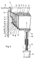
- In Figur (5) ist eine nur teilweise dargestellte Filterkerze (61) gezeigt, die aus insgesamt sechs Filterkerzensegmenten (62, 63, 64, 65, 66, 67) zusammengesetzt ist, welche teleskopisch ineinanderschiebbar sind und aus einem porösen filterwirksamen Material bestehen. Die Filterkerzensegmente (62) bis (67) sind jeweils zylindrisch ausgebildet und weisen an ihren oberen Rändern Außenstege (68, 69, 70̸, 71, 72, 73) auf, die sich jeweils über den gesamten Umfang erstrecken und schräg nach oben gerichet sind. Die Außenstege (69, 70̸, 71, 72, 73) korrespondieren mit jeweils am unteren Ende vorspringenden Innenstegen (74, 75, 76, 77, 78) an den Filterkerzensegmenten (62, 63, 64, 65, 66), welche schräg nach unten gerichtet sind.
- Ihr Konuswinkel entspricht dem der Außenstege (69, 70̸, 71, 72, 73), so daß zwischen diesen und den Innenstegen (74, 75, 76, 77, 78) in auseinandergeschobenem Zustand eine flächige Anlage gegeben ist.
- Das obere Filterkerzensegment (62) hängt in einer Öffnung eines Gehäuses (79) eines Filterapparates, der hier ansonsten nicht näher dargestellt ist. Hierzu stützt sich das obere Filterkerzensegment (62) über den Außensteg (68) an einer entsprechend konisch gestalteten Auflagefläche der Öffnung ab. Sämtliche Filterkerzensegmente (62) bis (67) werden von außen nach innen durchströmt, wie schon oben zum Ausführungsbeispiel gemäß Figur (1) beschrieben.
- Unterhalb der Filterkerze (61) ist ein Hubstempel (80̸) vorgesehen, der über eine Endplatte (81) an dem unteren Filterkerzensegment (67) anliegt. Durch den Hubstempel (80̸) erstreckt sich eine Spindel (82), die von einem Elektromotor (83) angetrieben ist. Durch Verdrehen der Spindel (82) kann der Hubstempel (80̸) vertikal nach oben oder nach unten verfahren werden.
- Im dargestellten Zustand ist der Hubstempel (80̸) teilweise nach oben ausgefahren, so daß die Filterkerzensegmente (63, 64, 65, 66, 67) schon ineinandergeschoben sind. Für deren gegenseitige Mitnahme sind an den Außenseiten Mitnahmeringe (84, 85, 86, 87, 88) vorgesehen, auf denen sich das jeweils obere Filterkerzensegment (62, 63, 64, 65, 66) beim Ineinanderschieben abstützen kann. Statt der Mitnahmeringe (84, 85, 86, 87, 88) kann auch eine entsprechend breite Endplatte (81) verwendet werden, auf der sich dann nacheinander die Filterkerzensegmente (62, 63, 64, 65, 66, 67) beim Hochfahren des Hubstempels (80̸) absetzen.
Claims (18)
- Filterkerze (1, 11, 31, 51, 61), inbesondere für Filterapparate für die Gasfiltration, wobei die Filterkerze (1, 11, 31, 51, 61) aus einem eigenstabilen, porösen, gesinterten Kunststoff- oder Metall oder aus einem eigenstabilen, porösen Keramikmaterial besteht,
dadurch gekennzeichnet, daß die Filterkerze (1, 11, 31, 51, 61) in Filterkerzensegmente (2, 3; 12, 13, 14; 32, 33, 34; 52, 53, 54; 62, 63, 64, 65, 66, 67) unterteilt ist, die aus einer Transportposition, bei der die Filterkerzensegmente (2, 3; 12, 13, 14; 32, 33, 34; 52, 53, 54; 62, 63, 64, 65, 66, 67) teleskopisch ineinandergeschoben sind, in eine Filtrierposition bringbar sind, bei der die Filterkerzensegmente (2, 3; 12, 13, 14; 32, 33, 34; 52, 53, 54; 62, 63, 64, 65, 66, 67) eine große Filterkerze bildend vollständig auseinandergezogen sind. - Filterkerze nach Anspruch 1,
dadurch gekennzeichnet, daß die Filterkerzensegmente (2, 3; 12, 13, 14; 32, 33, 34; 52, 53, 54; 62, 63, 64, 65, 66, 67) sich im auseinandergeschobenen Zustand formschlüssig aneinander abstützen. - Filterkerze nach Anspruch 2,
dadurch gekennzeichnet, daß sich die Abstützung über den gesamten Umfang erstreckt. - Filterkerze nach Anspruch 2 oder 3,
dadurch gekennzeichnet, daß die Filterkerzensegmente (2, 3; 12, 13, 14; 32, 33, 34; 62, 63, 64, 65, 66, 67) sich im auseinandergeschobenen Zustand gegenseitig abstützende Vorsprünge (4, 5; 15, 16, 17, 18; 36, 37, 38, 39; 69, 70̸, 71, 72, 73, 74, 75, 76, 77, 78) aufweisen. - Filterkerze nach Anspruch 4,
dadurch gekennzeichnet, daß die Vorsprünge als untenseitig nach innen und obenseitig nach außen vorstehende Stege (4, 5; 15, 16, 17, 18; 36, 37, 38, 39; 69, 70̸, 71, 72, 73, 74, 75, 76, 77, 78) ausgebildet sind. - Filterkerze nach Anspruch 5,
dadurch gekennzeichnet, daß die Stege (36, 37, 38, 39) U-förmig ausgebildet sind. - Filterkerze nach Anspruch 5,
dadurch gekennzeichnet, daß die Stege (15, 16, 17, 18) waagerecht ausgerichtet sind. - Filterkerze nach Anspruch 5,
dadurch gekennzeichnet, daß die nach innen vorstehenden Stege (74, 75, 76, 77, 78) schräg nach unten und die nach außen vorstehenden Stege (69, 70̸, 71, 72, 73) schräg nach oben gerichtet sind. - Filterkerze nach Anspruch 5,
dadurch gekennzeichnet, daß die nach innen gerichteten Stege (4) rinnenförmig und die nach außen gerichteten Stege (5) wulstförmig ausgebildet sind. - Filterkerze nach Anspruch 2 oder 3,
dadurch gekennzeichnet, daß die Filterkerzensegmente (52, 53, 54) derart konisch ausgebildet sind, daß der untere Durchmesser des jeweils äußeren Filterkerzensegmentes (52, 53) geringer als der obere Durchmesser des jeweils benachbarten inneren Filterkerzensegmentes (53, 54) ist. - Filterkerze nach einem der Ansprüche 2 bis 10̸,
dadurch gekennzeichnet, daß das unterste Filterkerzensegment mit einem Zusatzgewicht beschwert ist. - Filterkerze nach einem der Ansprüche 1 bis 11,
dadurch gekennzeichnet, daß die Filterkerzensegmente (12, 13, 14) in auseinandergeschobenem Zustand über Dichtungsringe (19, 20̸) aneinanderliegen. - Filterkerze nach einem der Ansprüche 1 bis 12,
dadurch gekennzeichnet, daß am Filterkerzensegment (14, 34) mit dem kleinsten Querschnitt innenseitig ein über das Filterkerzenelement (12, 32) mit dem größten Querschnitt vorstehender Strang (24, 41) befestigt ist. - Filterkerze nach Anspruch 13,
dadurch gekennzeichnet, daß der Strang als Seil (24) ausgebildet ist. - Filterkerze nach Anspruch 13,
dadurch gekennzeichnet, daß der Strang als Stange (41) ausgebildet ist. - Filterkerze nach Anspruch 15,
dadurch gekennzeichnet, daß die Stange (41) über eine Feder (43) mit dem Filterkerzensegment (34) verbunden ist. - Filterkerze nach einem der Ansprüche 1 bis 16,
dadurch gekennzeichnet, daß der Filterkerze (61) eine Hubeinrichtung (80̸, 81, 82, 83) zugeordnet ist, deren Hubstempel (80̸) am Boden (81) des untersten Filterkerzensegments (67) zur Anlage bringbar und nach oben ausfahrbar ist. - Filterkerze nach einem der Ansprüche 13 bis 16,
dadurch gekennzeichnet, daß die ineinanderschiebbaren Filterkerzensegmente (13, 14; 63, 64, 65, 66, 67) außenseitig Mitnahmevorsprünge (25, 26; 84, 85, 86, 87, 88) aufweisen.
Applications Claiming Priority (2)
| Application Number | Priority Date | Filing Date | Title |
|---|---|---|---|
| DE4017071A DE4017071A1 (de) | 1990-05-26 | 1990-05-26 | Filterkerze |
| DE4017071 | 1990-05-26 |
Publications (3)
| Publication Number | Publication Date |
|---|---|
| EP0459163A2 EP0459163A2 (de) | 1991-12-04 |
| EP0459163A3 EP0459163A3 (en) | 1992-03-18 |
| EP0459163B1 true EP0459163B1 (de) | 1995-08-09 |
Family
ID=6407295
Family Applications (1)
| Application Number | Title | Priority Date | Filing Date |
|---|---|---|---|
| EP91106996A Expired - Lifetime EP0459163B1 (de) | 1990-05-26 | 1991-04-30 | Filterkerze |
Country Status (9)
| Country | Link |
|---|---|
| US (1) | US5223012A (de) |
| EP (1) | EP0459163B1 (de) |
| AT (1) | ATE126087T1 (de) |
| CA (1) | CA2042705A1 (de) |
| DE (2) | DE4017071A1 (de) |
| DK (1) | DK0459163T3 (de) |
| ES (1) | ES2079511T3 (de) |
| FI (1) | FI92652C (de) |
| NO (1) | NO177486C (de) |
Families Citing this family (41)
| Publication number | Priority date | Publication date | Assignee | Title |
|---|---|---|---|---|
| US5401406A (en) * | 1992-12-11 | 1995-03-28 | Pall Corporation | Filter assembly having a filter element and a sealing device |
| FR2740701B1 (fr) * | 1995-11-02 | 1997-12-19 | Amblard Albert | Dispositif de filtration a montage etanche |
| JP4195099B2 (ja) * | 1997-03-21 | 2008-12-10 | シーメンス アクチエンゲゼルシヤフト | 含じんガス用フィルタとそのフィルタカートリッジ |
| WO1999052617A1 (en) * | 1998-04-15 | 1999-10-21 | Porous Media Corporation | Stacked conical filtration or separation apparatus |
| DE50301103D1 (de) | 2002-03-19 | 2005-10-06 | Bard Dublin Itc Ltd | Vakuum-biopsievorrichtung |
| CA2479349C (en) | 2002-03-19 | 2012-07-03 | Bard Dublin Itc Limited | Biopsy device and biopsy needle module that can be inserted into the biopsy device |
| DE10314240B4 (de) | 2003-03-29 | 2025-05-28 | Bard Dublin Itc Ltd. | Druckerzeugungseinheit |
| SE526406C2 (sv) * | 2004-01-14 | 2005-09-06 | Silvent Ab | Ljuddämpare för pneumatiska maskiner |
| US8052615B2 (en) | 2004-07-09 | 2011-11-08 | Bard Peripheral Vascular, Inc. | Length detection system for biopsy device |
| US7517321B2 (en) | 2005-01-31 | 2009-04-14 | C. R. Bard, Inc. | Quick cycle biopsy system |
| CA2616823C (en) | 2005-08-10 | 2014-06-03 | C.R. Bard Inc. | Single-insertion, multiple sampling biopsy device usable with various transport systems and integrated markers |
| EP1921998B8 (de) | 2005-08-10 | 2021-07-07 | C.R.Bard, Inc. | Biopsievorrichtung mit linearantrieb für mehrfache probennahme mit einzeleinführung |
| CA2616714C (en) | 2005-08-10 | 2017-01-24 | Jon Taylor | Single-insertion, multiple sample biopsy device with integrated markers |
| WO2008024684A2 (en) | 2006-08-21 | 2008-02-28 | C.R. Bard, Inc. | Self-contained handheld biopsy needle |
| DE202006014962U1 (de) * | 2006-09-27 | 2008-02-07 | Mann + Hummel Gmbh | Filtereinrichtung |
| SI2086418T1 (sl) | 2006-10-06 | 2011-05-31 | Bard Peripheral Vascular Inc | Sistem za obdelavo tkiva z zmanjšano izpostavljenostjo operaterja |
| EP3714798A3 (de) | 2006-10-24 | 2020-12-16 | C. R. Bard, Inc. | Biopsienadeln für grosse proben mit geringem aspektverhältnis |
| US8241225B2 (en) | 2007-12-20 | 2012-08-14 | C. R. Bard, Inc. | Biopsy device |
| US8172771B2 (en) * | 2008-02-13 | 2012-05-08 | Suros Surgical Systems, Inc. | Tissue collection system |
| EP2408378A4 (de) | 2009-03-16 | 2013-10-09 | Bard Inc C R | Biopsievorrichtung mit rotationsschneidevorrichtung |
| CA2965976C (en) * | 2009-04-15 | 2019-05-07 | C.R. Bard, Inc. | Biopsy apparatus having integrated fluid management |
| WO2010144012A1 (en) * | 2009-06-11 | 2010-12-16 | Camfil Ab | Compactable air filter |
| WO2011019343A1 (en) | 2009-08-12 | 2011-02-17 | C.R. Bard, Inc. | Biopsy appaparatus having integrated thumbwheel mechanism for manual rotation of biopsy cannula |
| US8283890B2 (en) | 2009-09-25 | 2012-10-09 | Bard Peripheral Vascular, Inc. | Charging station for battery powered biopsy apparatus |
| US8430824B2 (en) | 2009-10-29 | 2013-04-30 | Bard Peripheral Vascular, Inc. | Biopsy driver assembly having a control circuit for conserving battery power |
| US20110105946A1 (en) * | 2009-10-31 | 2011-05-05 | Sorensen Peter L | Biopsy system with infrared communications |
| US20140020561A1 (en) * | 2012-07-18 | 2014-01-23 | Glen Aery | Segmented stackable filter assembly for filtering a gas and method of manufacturing same |
| DE102012107097A1 (de) * | 2012-08-02 | 2014-05-22 | USPRO UG (haftungsbeschränkt) | Filter in Modulbauweise |
| ES2875575T3 (es) | 2013-03-20 | 2021-11-10 | Bard Peripheral Vascular Inc | Dispositivo de biopsia |
| US10456120B2 (en) | 2013-11-05 | 2019-10-29 | C. R. Bard, Inc. | Biopsy device having integrated vacuum |
| AU2015393933B2 (en) | 2015-05-01 | 2020-03-19 | C. R. Bard, Inc. | Biopsy device |
| FR3062318B1 (fr) * | 2017-02-02 | 2020-06-19 | Abp - Aquilina Bouvier Pool | Filtre destine a un dispositif de filtration d'eau |
| DE102017010349B4 (de) * | 2017-11-09 | 2021-08-12 | Hydac Fluidcarecenter Gmbh | Filtervorrichtung |
| GB201820636D0 (en) * | 2018-12-18 | 2019-01-30 | Madison Filter 981 Ltd | Modular filter element and coupling |
| PL4087671T3 (pl) * | 2020-05-22 | 2026-01-05 | Unifrax I Llc | Sposób i urządzenie do łączenia modułowych filtrów świecowych |
| EP3919160B1 (de) * | 2020-06-03 | 2024-10-02 | Pall Corporation | Kerzenfilter |
| MX2023000566A (es) * | 2020-07-13 | 2023-03-15 | Evoqua Water Tech Llc | Filtro de medios regenerativos con difusor de flujo. |
| US20220088541A1 (en) * | 2020-09-18 | 2022-03-24 | Pall Corporation | Filter with interconnected hollow elements and method of use |
| US11612837B2 (en) | 2020-09-18 | 2023-03-28 | Pall Corporation | Filter with interconnected hollow elements and method of use |
| JP2022089422A (ja) * | 2020-12-04 | 2022-06-16 | 株式会社鷺宮製作所 | ストレーナ及び弁装置並びに冷凍サイクルシステム |
| US12215555B2 (en) * | 2023-03-21 | 2025-02-04 | Saudi Arabian Oil Company | Systems and methods for operating candle filters to recover glycols from drilling operations |
Family Cites Families (15)
| Publication number | Priority date | Publication date | Assignee | Title |
|---|---|---|---|---|
| US2220772A (en) * | 1939-01-25 | 1940-11-05 | Millard Ethel | Filter and trap for plumbing fixtures |
| US2521107A (en) * | 1949-01-12 | 1950-09-05 | Robert D Wiley | Filtering device |
| US2863562A (en) * | 1953-06-26 | 1958-12-09 | Sintercast Corp America | Corrosion resistant sintered iron-silicon filter |
| US3349919A (en) * | 1964-09-28 | 1967-10-31 | Rosaen Filter Co | Telescoping filter assembly |
| US3334748A (en) * | 1965-04-29 | 1967-08-08 | Rosaen Filter Co | Variable capacity filter devices |
| US3451197A (en) * | 1967-05-02 | 1969-06-24 | Slick Corp | Baghouse apparatus |
| SU584137A1 (ru) * | 1976-03-25 | 1977-12-15 | Ордена Октябрьской Революции Всесоюзный Государственный Проектно-Изыскательский И Научно-Исследовательский Институт Энергетических Систем И Электрических Сетей "Энергосетьпроект"(Среднеазиатское Отделение) | Гидравлическа муфта |
| US4228012A (en) * | 1978-10-26 | 1980-10-14 | Pall Corporation | End cap coupler system for linking one filter cartridge to another filter cartridge or functional member |
| JPS55119412A (en) * | 1979-03-07 | 1980-09-13 | Ngk Insulators Ltd | Ceramic filter for high temperature |
| DE3024324A1 (de) * | 1980-06-27 | 1982-01-21 | Herding GmbH Entstaubungsanlagen, 8450 Amberg | Filterkoerper zum abscheiden von fest- und/oder schwebstoffen und verfahren zu dessen herstellung |
| US4692176A (en) * | 1986-01-07 | 1987-09-08 | Westinghouse Electric Corp. | Thermal expansion compensating back flush manifold |
| DE8709095U1 (de) * | 1987-05-14 | 1987-10-29 | Thomas Josef Heimbach GmbH & Co., 52353 Düren | Filtermittel |
| DE8715130U1 (de) * | 1987-11-13 | 1988-01-28 | Foseco International Ltd., Birmingham | Filter zur Filtration von Staub aus Heißgas |
| DE3817793A1 (de) * | 1988-05-26 | 1989-11-30 | Seitz Filter Werke | Rohrfoermiges filterelement |
| ES2093610T3 (es) * | 1988-06-04 | 1997-01-01 | Herding Entstaubung | Filtro para la separacion de particulas solidas de medios fluidos o liquidos calientes. |
-
1990
- 1990-05-26 DE DE4017071A patent/DE4017071A1/de not_active Withdrawn
-
1991
- 1991-04-30 EP EP91106996A patent/EP0459163B1/de not_active Expired - Lifetime
- 1991-04-30 DE DE59106186T patent/DE59106186D1/de not_active Expired - Fee Related
- 1991-04-30 ES ES91106996T patent/ES2079511T3/es not_active Expired - Lifetime
- 1991-04-30 AT AT91106996T patent/ATE126087T1/de active
- 1991-04-30 DK DK91106996.1T patent/DK0459163T3/da active
- 1991-05-10 US US07/698,102 patent/US5223012A/en not_active Expired - Fee Related
- 1991-05-16 CA CA002042705A patent/CA2042705A1/en not_active Abandoned
- 1991-05-20 FI FI912430A patent/FI92652C/fi active
- 1991-05-24 NO NO912009A patent/NO177486C/no unknown
Non-Patent Citations (1)
| Title |
|---|
| SOVIET PATENTS ABSTRACTS, Section Ch, Woche 8511, Klasse B, AN 85-067143/11, Derwent Publications Ltd, London, GB; & SU-A-584 137 (BELORUSSIAN POLY) 15-08-1984 * |
Also Published As
| Publication number | Publication date |
|---|---|
| NO912009D0 (no) | 1991-05-24 |
| ES2079511T3 (es) | 1996-01-16 |
| ATE126087T1 (de) | 1995-08-15 |
| DE4017071A1 (de) | 1991-11-28 |
| NO912009L (no) | 1991-11-27 |
| US5223012A (en) | 1993-06-29 |
| FI912430A0 (fi) | 1991-05-20 |
| NO177486B (no) | 1995-06-19 |
| EP0459163A2 (de) | 1991-12-04 |
| CA2042705A1 (en) | 1991-11-27 |
| FI912430L (fi) | 1991-11-27 |
| FI92652B (fi) | 1994-09-15 |
| NO177486C (no) | 1995-09-27 |
| FI92652C (fi) | 1994-12-27 |
| DK0459163T3 (da) | 1995-11-27 |
| EP0459163A3 (en) | 1992-03-18 |
| DE59106186D1 (de) | 1995-09-14 |
Similar Documents
| Publication | Publication Date | Title |
|---|---|---|
| EP0459163A2 (de) | Filterkerze | |
| DE2349702C2 (de) | Verfahren und Vorrichtung zum Fraktionieren einer Suspension mittels Hydrozyklonen | |
| EP0562502B1 (de) | In ein Filtergehäuse einbaubare Filterpatrone | |
| DE69201440T2 (de) | Vorrichtung zum fördern von fliessfähigem schüttgut. | |
| DE102007057304A1 (de) | Filteranordnung | |
| EP0066921A2 (de) | Filterelement | |
| DE3000082A1 (de) | Behaelter | |
| DE3412000C2 (de) | ||
| DE3524640C2 (de) | Vorrichtung zur Behandlung von Flüssigkeiten | |
| DE2800513A1 (de) | Vorrichtung zum einspannen eines kassettenfilters in ein filtergehaeuse | |
| DE1611068C3 (de) | Rückspülfilter mit zylindrischem Käfig | |
| DE3238783C2 (de) | Filterkerze | |
| CH669911A5 (de) | ||
| DE2657031C3 (de) | Ausgleichsplatte für eine Druck* filtrationszelle | |
| DE3705803C2 (de) | Rückspülfilter | |
| WO2000035555A1 (de) | Modulfilter mit zumindest einem zulauf für unfiltrat und einem ablauf für das filtrat und mit zumindest einem filtermodul | |
| EP0810018B1 (de) | Rückspülbare Filteranordnung und Filterkerze | |
| DE2234528A1 (de) | Filtergeraet | |
| DE102017010349A1 (de) | Filterelement und Filtervorrichtung | |
| DE3249756C2 (de) | Filterkerze | |
| DE2934117C2 (de) | Rückspülbares Filter | |
| DE2928299C2 (de) | Vorrichtung zum Filtrieren von Flüssigkeiten | |
| DE4307472C2 (de) | Filter für Flüssigkeiten, Pasten oder andere hochviskose Medien | |
| DE9307614U1 (de) | Filterpatrone | |
| EP0480874B1 (de) | Filter zur Teilchenabscheidung |
Legal Events
| Date | Code | Title | Description |
|---|---|---|---|
| PUAI | Public reference made under article 153(3) epc to a published international application that has entered the european phase |
Free format text: ORIGINAL CODE: 0009012 |
|
| AK | Designated contracting states |
Kind code of ref document: A2 Designated state(s): AT BE CH DE DK ES FR GB IT LI LU NL SE |
|
| PUAL | Search report despatched |
Free format text: ORIGINAL CODE: 0009013 |
|
| AK | Designated contracting states |
Kind code of ref document: A3 Designated state(s): AT BE CH DE DK ES FR GB IT LI LU NL SE |
|
| 17P | Request for examination filed |
Effective date: 19920508 |
|
| 17Q | First examination report despatched |
Effective date: 19940131 |
|
| GRAA | (expected) grant |
Free format text: ORIGINAL CODE: 0009210 |
|
| AK | Designated contracting states |
Kind code of ref document: B1 Designated state(s): AT BE CH DE DK ES FR GB IT LI LU NL SE |
|
| REF | Corresponds to: |
Ref document number: 126087 Country of ref document: AT Date of ref document: 19950815 Kind code of ref document: T |
|
| REF | Corresponds to: |
Ref document number: 59106186 Country of ref document: DE Date of ref document: 19950914 |
|
| ET | Fr: translation filed | ||
| ITF | It: translation for a ep patent filed | ||
| GBT | Gb: translation of ep patent filed (gb section 77(6)(a)/1977) |
Effective date: 19951016 |
|
| REG | Reference to a national code |
Ref country code: DK Ref legal event code: T3 |
|
| REG | Reference to a national code |
Ref country code: ES Ref legal event code: FG2A Ref document number: 2079511 Country of ref document: ES Kind code of ref document: T3 |
|
| PG25 | Lapsed in a contracting state [announced via postgrant information from national office to epo] |
Ref country code: LU Free format text: LAPSE BECAUSE OF NON-PAYMENT OF DUE FEES Effective date: 19960430 |
|
| PLBE | No opposition filed within time limit |
Free format text: ORIGINAL CODE: 0009261 |
|
| STAA | Information on the status of an ep patent application or granted ep patent |
Free format text: STATUS: NO OPPOSITION FILED WITHIN TIME LIMIT |
|
| 26N | No opposition filed | ||
| PGFP | Annual fee paid to national office [announced via postgrant information from national office to epo] |
Ref country code: DK Payment date: 19970423 Year of fee payment: 7 |
|
| PG25 | Lapsed in a contracting state [announced via postgrant information from national office to epo] |
Ref country code: DK Free format text: LAPSE BECAUSE OF NON-PAYMENT OF DUE FEES Effective date: 19980430 |
|
| PGFP | Annual fee paid to national office [announced via postgrant information from national office to epo] |
Ref country code: SE Payment date: 19990412 Year of fee payment: 9 |
|
| PGFP | Annual fee paid to national office [announced via postgrant information from national office to epo] |
Ref country code: ES Payment date: 19990419 Year of fee payment: 9 |
|
| PGFP | Annual fee paid to national office [announced via postgrant information from national office to epo] |
Ref country code: NL Payment date: 19990422 Year of fee payment: 9 Ref country code: CH Payment date: 19990422 Year of fee payment: 9 Ref country code: BE Payment date: 19990422 Year of fee payment: 9 Ref country code: AT Payment date: 19990422 Year of fee payment: 9 |
|
| REG | Reference to a national code |
Ref country code: DK Ref legal event code: EBP |
|
| PG25 | Lapsed in a contracting state [announced via postgrant information from national office to epo] |
Ref country code: LI Free format text: LAPSE BECAUSE OF NON-PAYMENT OF DUE FEES Effective date: 20000430 Ref country code: CH Free format text: LAPSE BECAUSE OF NON-PAYMENT OF DUE FEES Effective date: 20000430 Ref country code: BE Free format text: LAPSE BECAUSE OF NON-PAYMENT OF DUE FEES Effective date: 20000430 Ref country code: AT Free format text: LAPSE BECAUSE OF NON-PAYMENT OF DUE FEES Effective date: 20000430 |
|
| PG25 | Lapsed in a contracting state [announced via postgrant information from national office to epo] |
Ref country code: SE Free format text: LAPSE BECAUSE OF NON-PAYMENT OF DUE FEES Effective date: 20000501 |
|
| PG25 | Lapsed in a contracting state [announced via postgrant information from national office to epo] |
Ref country code: ES Free format text: THE PATENT HAS BEEN ANNULLED BY A DECISION OF A NATIONAL AUTHORITY Effective date: 20000503 |
|
| BERE | Be: lapsed |
Owner name: THOMAS JOSEF HEIMBACH G.M.B.H. & CO. Effective date: 20000430 |
|
| PG25 | Lapsed in a contracting state [announced via postgrant information from national office to epo] |
Ref country code: NL Free format text: LAPSE BECAUSE OF NON-PAYMENT OF DUE FEES Effective date: 20001101 |
|
| REG | Reference to a national code |
Ref country code: CH Ref legal event code: PL |
|
| NLV4 | Nl: lapsed or anulled due to non-payment of the annual fee |
Effective date: 20001101 |
|
| EUG | Se: european patent has lapsed |
Ref document number: 91106996.1 |
|
| REG | Reference to a national code |
Ref country code: GB Ref legal event code: IF02 |
|
| REG | Reference to a national code |
Ref country code: ES Ref legal event code: FD2A Effective date: 20020204 |
|
| PG25 | Lapsed in a contracting state [announced via postgrant information from national office to epo] |
Ref country code: IT Free format text: LAPSE BECAUSE OF NON-PAYMENT OF DUE FEES Effective date: 20050430 |
|
| PGFP | Annual fee paid to national office [announced via postgrant information from national office to epo] |
Ref country code: DE Payment date: 20060227 Year of fee payment: 16 |
|
| PGFP | Annual fee paid to national office [announced via postgrant information from national office to epo] |
Ref country code: FR Payment date: 20060420 Year of fee payment: 16 |
|
| PGFP | Annual fee paid to national office [announced via postgrant information from national office to epo] |
Ref country code: GB Payment date: 20060426 Year of fee payment: 16 |
|
| GBPC | Gb: european patent ceased through non-payment of renewal fee |
Effective date: 20070430 |
|
| PG25 | Lapsed in a contracting state [announced via postgrant information from national office to epo] |
Ref country code: DE Free format text: LAPSE BECAUSE OF NON-PAYMENT OF DUE FEES Effective date: 20071101 |
|
| PG25 | Lapsed in a contracting state [announced via postgrant information from national office to epo] |
Ref country code: GB Free format text: LAPSE BECAUSE OF NON-PAYMENT OF DUE FEES Effective date: 20070430 |
|
| PG25 | Lapsed in a contracting state [announced via postgrant information from national office to epo] |
Ref country code: FR Free format text: LAPSE BECAUSE OF NON-PAYMENT OF DUE FEES Effective date: 20070430 |