EP0457972A1 - Locking bar and counter holder of a locking for hinged side boards of lorries - Google Patents
Locking bar and counter holder of a locking for hinged side boards of lorries Download PDFInfo
- Publication number
- EP0457972A1 EP0457972A1 EP90125628A EP90125628A EP0457972A1 EP 0457972 A1 EP0457972 A1 EP 0457972A1 EP 90125628 A EP90125628 A EP 90125628A EP 90125628 A EP90125628 A EP 90125628A EP 0457972 A1 EP0457972 A1 EP 0457972A1
- Authority
- EP
- European Patent Office
- Prior art keywords
- bolt
- contact surface
- holder
- counter
- lock
- Prior art date
- Legal status (The legal status is an assumption and is not a legal conclusion. Google has not performed a legal analysis and makes no representation as to the accuracy of the status listed.)
- Granted
Links
Images

Classifications
-
- E—FIXED CONSTRUCTIONS
- E05—LOCKS; KEYS; WINDOW OR DOOR FITTINGS; SAFES
- E05C—BOLTS OR FASTENING DEVICES FOR WINGS, SPECIALLY FOR DOORS OR WINDOWS
- E05C19/00—Other devices specially designed for securing wings, e.g. with suction cups
- E05C19/10—Hook fastenings; Fastenings in which a link engages a fixed hook-like member
Definitions
- the invention relates to a bolt and a counterholder of a bolt lock for hinged side walls of trucks according to the preamble of the preceding patent claim 1.
- Bolt locks for foldable side walls of trucks are available in a wide variety of designs.
- a very widespread latch tension lock is described for example in DE-PS 16 78 155. Its bolt is hook-shaped and screwed into a bolt stub so that the end position of the bolt can be adjusted by turning the bolt.
- a frequently used slide bolt lock is given for example in DE-PS 23 61 914. In order to give such fastenings a catch-up ability, they have a run-up surface on the bolt and / or on the counter-holder which runs obliquely to the direction of movement of the bolt.
- latch locks of the known type have a significant disadvantage.
- the invention was based on the object of developing a device of the type in question so that when the cargo is pressed against the side wall the latch lock cannot be fully opened and this pressure is immediately noticeable when an attempt is made to open the lock.
- the bolt lock can only be opened until the contact surface on the bolt presses against the contact surface on the counter holder. Since the contact surface lies in one step at the transition from the first to the second part of the run-up surface, the drop side falls slightly outwards so that the internal pressure is immediately noticeable.
- the bolt and the counter holder can easily be designed so that a conspicuous drop of 10, 15 or even 20 mm is obtained.
- the contact surface on the bolt and the contact surface on the counterholder run approximately perpendicular to the direction of movement of the bolt, the internal pressure must be removed from the side wall in order to open it again so that it can be brought back into its completely vertical position. As a result, the contact surface on the bolt and the contact surface on the counterholder disengage, so that the bolt lock can be opened completely and the side wall can be folded down.
- the bolt has a bolt and two scissor-like bolt parts pivotable against each other.
- the drive of the bolt and the pivotable bolt parts is such that, during the closing process, the pivotable bolt parts are first inserted into an opening in the counter-holder and then spread apart by subsequent advancement of the bolt.
- the pivotable bolt parts and the bolt are collectively referred to in this patent as a bolt.
- the pivotable latch parts each have lugs at their free ends, which engage behind the opening of the counterholder when the latch is closed.
- the lugs have inclined surfaces with an inclination of about 45 o with respect to the direction of movement of the bolt, so that when the lock is pressed internally, one of the lugs slides on the adjacent edge of the opening in the counterholder when the lock is opened, which is why there is no effective inhibition of the opening process . Also, the patent does not mention anywhere that the bolt lock could not be opened completely when the inner wall was pressed.
- a bolt lock is known, which differs from that described in DE-PS 38 17 220 in that the bolt is cylindrical and the pivotable bolt parts are replaced by a sleeve, which on its outer End is divided into elastic fingers by axially running, crosswise machined slots in the sleeve, which by the bolt can be spread.
- the fingers have lugs on their outer ends, which engage behind an opening in the counterholder when the closure is closed.
- the bolt is made up of several parts and is therefore weaker than a one-piece bolt, as is the case with the bolt according to the invention. If, after pulling back the bolt from the pivotable locking parts or from the slotted sleeve, they protrude into the counterholder alone, then the connection is weakened so that it cannot withstand a greater internal pressure and the pivoting locking parts or the sleeve are bent or even break off. In both locks, when the bolt is opened, the bolt is reduced in thickness, so that a drop in the side wall of a maximum of 2 to 3 mm can occur when the cargo is pressed against the side wall. However, due to its insignificance, this is not sufficient to make a possible existing charge pressure noticeable.
- the hook-shaped bolt engages in the closed position behind a bar on the counter-holder.
- the hook bolt can be T-shaped.
- the contact surface can be provided on at least one lateral extension on the crossbar of the hook bolt. In this case, two such lateral extensions are preferably provided, on each of which a contact surface is arranged. A part of the ramp surface is preferably provided on each lateral extension.
- the hook bolt it is also possible to design the hook bolt as a double-angled hook bolt in the case of a bolt-type tension lock and to provide the contact surface within the space delimited by the double angled portion.
- the counter-holder has an opening into which the bolt is inserted in the closed position.
- the counter holder can consist of a stanchion into which the opening mentioned is cut. But even with a slide bolt lock, contact surfaces could be provided in a similar manner on lateral extensions, as is the case with the above-mentioned embodiment of a bolt lock.
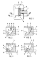
- the device according to the invention of the first embodiment consists of a bolt 11, which is designed as a T-shaped double hook, and a counter-holder 14, which has the shape of a pocket.
- the counter-holder 14 has a bar 15 divided in the middle, behind which the double hook engages in the closed position.
- Lugs 16 are provided on the side of the T-bar of the double hook 11 and come into contact with their contact surfaces 12 on contact surfaces 13 of the counter-holder 14 when the closure is opened, if there is pressure on the side wall from the inside.
- a complete opening of the lock is only possible in such a case if the side wall is relieved of the internal pressure and brought into its completely vertical position, since then the contact surfaces 12 and 13 move past one another when the latch is extended into the open position. So that a bolt lock provided with this bolt has a recovery capability, it has ramp surfaces 17 and 19, which correspond to ramp surfaces 17 and 20 on the counter-holder 14. Between the run-up surfaces 18 and 20 there is a step on the counter-holder 14 in which the contact surface 13 is located. This level is responsible for the fact that when there is internal pressure on the drop side when the lock is opened, the drop side clearly falls outwards, so that the inside pressure is recognized immediately.
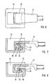
- the device according to the invention of the second embodiment has a bolt which is designed as a double-angled hook bolt 21. In the closed position, it engages with its free end behind a bar 25 of a counter-holder 24, which is also designed as a pocket.
- the contact surface 23 on the counter-holder 24 lies between the two parts 28 and 30 of a run-up surface, to which a run-up surface 27 on the hook 21 corresponds.
- the contact surface 23 lies in one Step between the two parts 28 and 30 of the ramp surface. The operation is the same as that of the first embodiment.
- the device according to the invention of the third embodiment has a slide bolt 31 which, in the closed position, is inserted into an opening 35 of a counter-holder 34, which here consists of a stanchion.
- the latch has an abutment surface 32, which comes into contact with internal pressure against the side wall in the course of the opening process with a surface serving as abutment surface 33 behind the opening 34 of the stanchion 35.
- the contact surface 32 on the bolt 31 lies between the two parts 37 and 39 of the ramp surface.
- the mode of operation corresponds to that of the second and third embodiments.
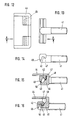
- the device of the fourth embodiment according to the invention has a T-shaped hook bolt 41 and a counter-holder 44, which has the shape of a pocket.
- the counter-holder 44 has a bar 45 divided in the middle, behind which the hook bolt engages in the closed position.
- the bolt 41 has a run-up surface consisting of two parts 47, 49 separated by a step, a contact surface 42 being located in the step.
- the counter-holder 44 has a run-up surface consisting of two parts 48, 50 separated by a step, a contact surface 43 being located in the step.
- the mode of operation is readily apparent and corresponds to that of the three other embodiments.
Landscapes
- Engineering & Computer Science (AREA)
- Mechanical Engineering (AREA)
- Lock And Its Accessories (AREA)
- Fittings On The Vehicle Exterior For Carrying Loads, And Devices For Holding Or Mounting Articles (AREA)
- Seats For Vehicles (AREA)
- Gears, Cams (AREA)
- Vehicle Step Arrangements And Article Storage (AREA)
- Hinges (AREA)
- Bag Frames (AREA)
- Pressure Vessels And Lids Thereof (AREA)
- Clamps And Clips (AREA)
- Mutual Connection Of Rods And Tubes (AREA)
- Connection Of Plates (AREA)
Abstract
Description
Die Erfindung betrifft einen Riegel und einen Gegenhalter eines Riegelverschlusses für abklappbare Bordwände von Lastfahrzeugen gemäß dem Oberbegriff des vorstehenden Patentanspruchs 1.The invention relates to a bolt and a counterholder of a bolt lock for hinged side walls of trucks according to the preamble of the preceding patent claim 1.
Riegelverschlüsse für abklappbare Bordwände von Lastfahrzeugen gibt es in den verschiedensten Ausführungsformen. Ein sehr weit verbreiteter Riegelspannverschluß ist beispielsweise in der DE-PS 16 78 155 beschrieben. Sein Riegel ist hakenförmig ausgebildet und in einen Riegelstumpf eingeschraubt, so daß durch Verdrehen des Riegels die Endlage des Riegels verstellt werden kann. Ein vielfach verwendeter Schubriegelverschluß ist beispielsweise in der DE-PS 23 61 914 angegeben. Um solchen Verschlüssen ein Heranholvermögen zu erteilen, weisen sie am Riegel und/oder am Gegenhalter eine schräg zur Bewegungsrichtung des Riegels verlaufende Auflauffläche auf.Bolt locks for foldable side walls of trucks are available in a wide variety of designs. A very widespread latch tension lock is described for example in DE-PS 16 78 155. Its bolt is hook-shaped and screwed into a bolt stub so that the end position of the bolt can be adjusted by turning the bolt. A frequently used slide bolt lock is given for example in DE-PS 23 61 914. In order to give such fastenings a catch-up ability, they have a run-up surface on the bolt and / or on the counter-holder which runs obliquely to the direction of movement of the bolt.
Es hat sich gezeigt, daß Riegelverschlüsse der bekannten Art einen wesentlichen Nachteil aufweisen. Beim Transport der verschiedensten Güter, wie z.B. gefüllten Säcken, kommt es häufig vor, daß die Ladung verrutscht und sich gegen eine Bordwand legt. Wird dann der Verschluß der Bordwand geöffnet, so wird die Bordwand nach unten geschleudert, wobei das Ladegut herunterfällt. Dabei kann es zu Verletzungen kommen.It has been shown that latch locks of the known type have a significant disadvantage. When transporting a wide variety of goods, such as filled sacks, it often happens that the load slips and lies against a side wall. If the closure of the drop side is then opened, the drop side is flung down, the load falling down. Injuries can result.
Der Erfindung lag die Aufgabe zugrunde, eine Vorrichtung der in Rede stehenden Art so weiterzubilden, daß bei Druck von Ladegut gegen die Bordwand der Riegelverschluß nicht vollständig geöffnet werden kann und dieser Druck beim Versuch des Öffnens des Verschlusses sich sofort auffällig bemerkbar macht.The invention was based on the object of developing a device of the type in question so that when the cargo is pressed against the side wall the latch lock cannot be fully opened and this pressure is immediately noticeable when an attempt is made to open the lock.
Die Aufgabe wird bei einer Vorrichtung der in Rede stehenden Art durch die Hinzufügung der Merkmale des Kennzeichens des vorstehenden Anspruchs 1 gelöst.The object is achieved in a device of the type in question by adding the features of the characterizing part of the preceding claim 1.
Wenn beim Öffnen eines mit den erfindungsgemäßen Teilen ausgerüsteten Riegelverschlusses durch gegen die Bordwand drückendes Ladegut Druck auf die Bordwand ausgeübt wird, dann läßt sich der Riegelverschluß zunächst nur so weit öffnen, bis die Anlagefläche am Riegel gegen die Anlagefläche am Gegenhalter drückt. Da am Übergang vom ersten zum zweiten Teil der Auflauffläche die Anlagefläche in einer Stufe liegt, fällt dabei die Bordwand etwas nach außen, so daß der Innendruck sich sofort auffällig bemerkbar macht. Der Riegel und der Gegenhalter können ohne weiteres so gestaltet werden, daß ein auffälliger Ausfall von 10, 15 oder sogar 20 mm erhalten wird. Da die Anlagefläche am Riegel und die Anlagefläche am Gegenhalter in etwa senkrecht zur Bewegungsrichtung des Riegels verlaufen, muß zum weiteren Öffnen der Innendruck von der Bordwand weggenommen werden, damit diese wieder in ihre vollständig senkrechte Lage gebracht werden kann. Dadurch kommen die Anlagefläche am Riegel und die Anlagefläche am Gegenhalter außer Eingriff, so daß der Riegelverschluß vollständig geöffnet und die Bordwand abgeklappt werden kann.If pressure is exerted on the side wall when a bolt lock equipped with the parts according to the invention is pressed by a load pressing against the side wall, the bolt lock can only be opened until the contact surface on the bolt presses against the contact surface on the counter holder. Since the contact surface lies in one step at the transition from the first to the second part of the run-up surface, the drop side falls slightly outwards so that the internal pressure is immediately noticeable. The bolt and the counter holder can easily be designed so that a conspicuous drop of 10, 15 or even 20 mm is obtained. Since the contact surface on the bolt and the contact surface on the counterholder run approximately perpendicular to the direction of movement of the bolt, the internal pressure must be removed from the side wall in order to open it again so that it can be brought back into its completely vertical position. As a result, the contact surface on the bolt and the contact surface on the counterholder disengage, so that the bolt lock can be opened completely and the side wall can be folded down.
Mit dem Ausdruck "in etwa", wie er im Zusammenhang mit den Anlageflächen verwendet wird, ist gemeint, daß die Richtung dieser Anlageflächen bezüglich der Bewegungsrichtung des Riegels von der senkrechten hierzu verlaufenden Richtung nur so weit abweichen darf, daß bei Innendruck auf die Bordwand eine vollständige Hemmung des Öffnungsvorgangs des Verschlusses eintritt, nachdem die Anlageflächen aneinander in Anlage gekommen sind. Die Anlageflächen dürfen keinesfalls bezüglich der Bewegungsrichtung des Riegels so schräg stehen, daß die Anlageflächen beim Öffnen des Verschlusses aufeinandergleiten und ein vollständiges Öffnen des Verschlusses nicht verhindert wird.By the expression "approximately" as it is used in connection with the contact surfaces, it is meant that the direction of these contact surfaces with respect to the direction of movement of the bolt may only deviate from the direction perpendicular to this so that an internal pressure on the side wall causes a complete inhibition of the opening process of the closure occurs after the contact surfaces come into contact with one another. The contact surfaces must not be so inclined with respect to the direction of movement of the bolt that the contact surfaces slide on each other when the lock is opened and the lock is fully opened is not prevented.
Wenn der Riegel in einen Riegelstumpf eingeschraubt ist, an dem seinerseits der Betätigungsmechanismus des Riegelverschlusses angreift, so ist im Sinne der Erfindung nur der Riegel ohne Riegelstumpf zu verstehen.If the bolt is screwed into a bolt stump on which the actuating mechanism of the bolt lock engages, only the bolt without a bolt stump is to be understood in the sense of the invention.
Aus der DE-PS 38 17 220 ist ein Riegelverschluß bekannt, dessen Riegel einen Bolzen und zwei scherenartig gegeneinander verschwenkbare Riegelteile aufweist. Der Antrieb des Bolzens und der schwenkbaren Riegelteile ist dabei derart, daß beim Schließvorgang zunächst die schwenkbaren Riegelteile in eine Öffnung im Gegenhalter hineingeführt und dann durch anschließenden Vorschub des Bolzens auseinandergespreizt werden. Die schwenkbaren Riegelteile und der Bolzen werden in dieser Patentschrift gemeinsam als Riegel bezeichnet. Die schwenkbaren Riegelteile haben an ihrem freien Ende jeweils Nasen, die im geschlossenen Zustand des Riegels hinter die Öffnung des Gegenhalters greifen. Die Nasen haben aber bezüglich der Bewegungsrichtung des Riegels Schrägflächen mit einer Neigung von etwa 45o, so daß bei Innendruck auf die Bordwand beim Öffnen des Verschlusses eine der Nasen auf der benachbarten Kante der Öffnung im Gegenhalter aufgleitet, weshalb eine wirksame Hemmung des Öffnungsvorgangs nicht eintritt. Auch wird in der Patentschrift nirgends erwähnt, daß der Riegelverschluß bei Innendruck auf die Bordwand nicht vollständig geöffnet werden könnte.From DE-PS 38 17 220 a bolt lock is known, the bolt has a bolt and two scissor-like bolt parts pivotable against each other. The drive of the bolt and the pivotable bolt parts is such that, during the closing process, the pivotable bolt parts are first inserted into an opening in the counter-holder and then spread apart by subsequent advancement of the bolt. The pivotable bolt parts and the bolt are collectively referred to in this patent as a bolt. The pivotable latch parts each have lugs at their free ends, which engage behind the opening of the counterholder when the latch is closed. The lugs have inclined surfaces with an inclination of about 45 o with respect to the direction of movement of the bolt, so that when the lock is pressed internally, one of the lugs slides on the adjacent edge of the opening in the counterholder when the lock is opened, which is why there is no effective inhibition of the opening process . Also, the patent does not mention anywhere that the bolt lock could not be opened completely when the inner wall was pressed.
Weiterhin ist aus der DE-PS 37 17 310 ein Riegelverschluß bekannt, der sich von dem in der DE-PS 38 17 220 beschriebenen dadurch unterscheidet, daß der Bolzen zylindrisch ausgebildet ist und die schwenkbaren Riegelteile durch eine Hülse ersetzt sind, die an ihrem äußeren Ende durch axial verlaufende, kreuzweise in die Hülse eingearbeitete Schlitze in elastische Finger unterteilt ist, die durch den Bolzen gespreizt werden können. Die Finger tragen an ihren äußeren Enden Nasen, welche im geschlossenen Zustand des Verschlusses eine Öffnung im Gegenhalter hintergreifen. Wenn auch nirgends in der Patentschrift davon gesprochen wird, daß die Nasen senkrecht zur Bewegungsrichtung des Riegels verlaufende Anlageflächen aufweisen, so sind solche senkrechte Anlageflächen doch in den Zeichnungen gezeigt, die sich beim Öffnen des Verschlusses auch dann hinter der Öffnung im Gegenhalter verhaken können, wenn der Bolzen bereits eine Lage einnimmt, bei der er die elastischen Finger nicht mehr spreizt. In der gesamten Patentschrift wird nirgends davon gesprochen, daß durch die Anlageflächen an den Nasen ein vollständiges Öffnen des Verschlusses bei Innendruck auf die Bordwand verhindert werden könnte. Sie sind dafür auch viel zu klein.Furthermore, from DE-PS 37 17 310 a bolt lock is known, which differs from that described in DE-PS 38 17 220 in that the bolt is cylindrical and the pivotable bolt parts are replaced by a sleeve, which on its outer End is divided into elastic fingers by axially running, crosswise machined slots in the sleeve, which by the bolt can be spread. The fingers have lugs on their outer ends, which engage behind an opening in the counterholder when the closure is closed. Although nowhere in the patent does it say that the lugs have contact surfaces running perpendicular to the direction of movement of the bolt, such vertical contact surfaces are nevertheless shown in the drawings, which can also get caught behind the opening in the counterholder when the lock is opened if the bolt is already in a position in which it no longer spreads the elastic fingers. Nowhere in the entire patent specification is it mentioned that the contact surfaces on the lugs could prevent the closure from being opened completely when the inside pressure is exerted on the side wall. They are too small for that.
Bei beiden Verschlüssen ist der Riegel aus mehreren Teilen aufgebaut und damit schwächer als ein einstückiger Riegel, wie dies bei dem erfindungsgemäßen Riegel der Fall ist. Wenn außerdem nach Zurückziehen des Bolzens aus den schwenkbaren Riegelteilen bzw. aus der geschlitzten Hülse diese alleine in den Gegenhalter vorstehen, dann ist die Verbindung so geschwächt, daß sie einen größeren Innendruck nicht aushält und die schwenkbaren Riegelteile oder die Hülse verbogen werden oder sogar abbrechen. Bei beiden Verschlüssen tritt beim Öffnen durch das Ausfahren des Bolzens eine Verringerung der Dicke des Riegels ein, so daß bei Ladungsdruck gegen die Bordwand ein Ausfall der Bordwand von höchstens 2 bis 3 mm auftreten kann. Dieser ist aber wegen seiner Geringfügigkeit nicht ausreichend um einen eventuell vorhandenen Ladungsdruck auffällig zu machen. Sehr nachteilig ist an beiden Verschlüssen, daß der Riegel in eine sehr enge Ausnehmung im Gegenhalter eingeschoben werden muß, was sich sowohl beim Schließen als auch beim Öffnen sehr unangenehm bemerkbar macht. Beim Schließen muß die Bordwand so gehalten werden, daß man genau in die Ausnehmung trifft, während beim Öffnen die Nasen an den scherenartigen Teilen bzw. an der geschlitzten Hülse sich leicht zu beiden Seiten der Ausnehmung verhaken können.In both closures, the bolt is made up of several parts and is therefore weaker than a one-piece bolt, as is the case with the bolt according to the invention. If, after pulling back the bolt from the pivotable locking parts or from the slotted sleeve, they protrude into the counterholder alone, then the connection is weakened so that it cannot withstand a greater internal pressure and the pivoting locking parts or the sleeve are bent or even break off. In both locks, when the bolt is opened, the bolt is reduced in thickness, so that a drop in the side wall of a maximum of 2 to 3 mm can occur when the cargo is pressed against the side wall. However, due to its insignificance, this is not sufficient to make a possible existing charge pressure noticeable. It is very disadvantageous with both fasteners that the bolt has to be inserted into a very narrow recess in the counterholder, which is very unpleasantly noticeable both when closing and when opening. When closing the side wall must be held so that you hit exactly in the recess, while the Open the lugs on the scissor-like parts or on the slotted sleeve can easily get caught on both sides of the recess.
Bei einer Ausführungsform der erfindungsgemäßen Vorrichtung für einen Riegelspannverschluß greift der hakenförmig ausgebildete Riegel in der Schließstellung hinter eine Leiste am Gegenhalter. Der Hakenriegel kann T-förmig ausgebildet sein. Dabei kann die Anlagefläche auf mindestens einem seitlichen Fortsatz am Querbalken des Hakenriegels vorgesehen sein. Vorzugsweise sind in diesem Fall zwei solche seitliche Fortsätze vorgesehen, auf denen je eine Anlagefläche angeordnet ist. Vorzugsweise ist auf jedem seitlichen Fortsatz der eine Teil der Auflauffläche vorgesehen. Es ist aber auch möglich, bei einem Riegelspannverschluß den Hakenriegel als doppelt abgewinkelten Hakenriegel auszubilden und die Anlagefläche innerhalb des durch die doppelte Abwinkelung abgegrenzten Raums vorzusehen.In one embodiment of the device according to the invention for a bolt tension lock, the hook-shaped bolt engages in the closed position behind a bar on the counter-holder. The hook bolt can be T-shaped. The contact surface can be provided on at least one lateral extension on the crossbar of the hook bolt. In this case, two such lateral extensions are preferably provided, on each of which a contact surface is arranged. A part of the ramp surface is preferably provided on each lateral extension. However, it is also possible to design the hook bolt as a double-angled hook bolt in the case of a bolt-type tension lock and to provide the contact surface within the space delimited by the double angled portion.
Bei einer anderen Ausführungsform der erfindungsgemäßen Vorrichtung für einen Schubriegelverschluß weist der Gegenhalter eine Öffnung auf, in die der Riegel in der Schließstellung eingeschoben ist. In diesem Fall kann der Gegenhalter aus einer Runge bestehen, in welche die erwähnte Öffnung eingeschnitten ist. Aber auch bei einem Schubriegelverschluß könnten Anlageflächen in ähnlicher Weise an seitlichen Fortsätzen vorgesehen sein, wie dies bei der oben erwähnten Ausführungsform eines Riegelspannverschlusses der Fall ist.In another embodiment of the device for a sliding bolt lock according to the invention, the counter-holder has an opening into which the bolt is inserted in the closed position. In this case, the counter holder can consist of a stanchion into which the opening mentioned is cut. But even with a slide bolt lock, contact surfaces could be provided in a similar manner on lateral extensions, as is the case with the above-mentioned embodiment of a bolt lock.
Vier Ausführungsformen einer erfindungsgemäßen Vorrichtung werden nun anhand der beigefügten Zeichnungen näher erläutert.Four embodiments of a device according to the invention will now be explained in more detail with reference to the accompanying drawings.
In den Zeichnungen zeigen:
- Figur 1
- eine Aufsicht auf die erste Ausführungsform einer erfindungsgemäßen Vorrichtung;
- Figur 2
- einen Schnitt an der Linie II-II von Figur 1;
- Figur 3
- einen Schnitt an der Linie III-III von Figur 1;
- Figur 4
- einen Schnitt an der Linie II-II von Figur 1, wobei jedoch eine Phase während des Schließvorgangs gezeigt ist;
- Figur 5
- einen Schnitt an der Linie II-II von Figur 1, wobei jedoch eine Phase während des Öffnungsvorgangs gezeigt ist;
- Figur 6
- eine Aufsicht auf die zweite Ausführungsform der erfindungsgemäßen Vorrichtung;
- Figur 7
- einen Schnitt durch die Vorrichtung von Figur 6;
- Figur 8
- einen Schnitt durch die Vorrichtung von Figur 6, wobei jedoch eine Phase während des Öffnungsvorgangs gezeigt ist;
- Figur 9
- eine Aufsicht auf die dritte Ausführungsform der erfindungsgemäßen Vorrichtung;
- Figur 10
- einen Schnitt durch die Vorrichtung von Figur 9;
Figur 11- einen Schnitt durch die Vorrichtung von Figur 9, wobei jedoch eine Phase während des Öffnungsvorgangs gezeigt ist;
Figur 12- eine Aufsicht auf den Gegenhalter der vierten Ausführungsform;
Figur 13- eine Aufsicht auf den Riegel der vierten Ausführungsform;
Figur 14- eine Seitenansicht des
Riegels von Figur 13; Figur 15- einen Schnitt an der Linie
A-A von Figur 12und 13, wobei sich Riegel und Gegenhalter in der Schließstellung befinden; und Figur 16- einen Schnitt an der Linie
A-A von Figur 12und 13, wobei sich der Riegel während des Öffnens im Gegenhalter verhakt hat.
- Figure 1
- a top view of the first embodiment of a device according to the invention;
- Figure 2
- a section on the line II-II of Figure 1;
- Figure 3
- a section on the line III-III of Figure 1;
- Figure 4
- a section along the line II-II of Figure 1, but showing a phase during the closing process;
- Figure 5
- a section along the line II-II of Figure 1, but showing a phase during the opening process;
- Figure 6
- a plan view of the second embodiment of the device according to the invention;
- Figure 7
- a section through the device of Figure 6;
- Figure 8
- a section through the device of Figure 6, but showing a phase during the opening process;
- Figure 9
- a supervision of the third embodiment of the device according to the invention;
- Figure 10
- a section through the device of Figure 9;
- Figure 11
- a section through the device of Figure 9, but showing a phase during the opening process;
- Figure 12
- a plan view of the counter holder of the fourth embodiment;
- Figure 13
- a plan view of the bolt of the fourth embodiment;
- Figure 14
- a side view of the bolt of Figure 13;
- Figure 15
- a section on the line AA of Figures 12 and 13, wherein the bolt and counterholder are in the closed position; and
- Figure 16
- a section on the line AA of Figures 12 and 13, wherein the bolt has caught in the counterholder during opening.
Gemäß den Figuren 1 bis 5 besteht die erfindungsgemäße Vorrichtung der ersten Ausführungsform aus einem Riegel 11, der als T-förmiger Doppelhaken ausgebildet ist, und einem Gegenhalter 14, der die Form einer Tasche aufweist. Der Gegenhalter 14 besitzt eine in der Mitte unterteilte Leiste 15, hinter die der Doppelhaken in der Schließstellung greift. Seitlich am T-Balken des Doppelhakens 11 sind Ansätze 16 vorgesehen, die beim Öffnen des Verschlusses mit ihren Anlageflächen 12 an Anlageflächen 13 des Gegenhalters 14 in Anlage kommen, wenn auf der Bordwand von innen her Druck liegt. Ein vollständiges Öffnen des Verschlusses ist in einem solchen Fall nur möglich, wenn die Bordwand vom Innendruck entlastet und in ihre völlig senkrechte Lage gebracht wird, da sich dann die Anlageflächen 12 und 13 beim Ausfahren des Riegels in die Offenstellung aneinander vorbeibewegen. Damit ein mit diesem Riegel versehener Riegelverschluß ein Heranholvermögen aufweist, besitzt er Auflaufflächen 17 und 19, denen Auflaufflächen 17 und 20 am Gegenhalter 14 entsprechen. Zwischen den Auflaufflächen 18 und 20 liegt am Gegenhalter 14 eine Stufe vor, in der sich die Anlagefläche 13 befindet. Diese Stufe ist dafür verantwortlich, daß bei Innendruck auf die Bordwand beim Öffnen des Verschlusses die Bordwand deutlich nach außen fällt, so daß der Innendruck sofort erkannt wird.According to FIGS. 1 to 5, the device according to the invention of the first embodiment consists of a
Gemäß den Figuren 6 bis 8 besitzt die erfindungsgemäße Vorrichtung der zweiten Ausführungsform einen Riegel, der als doppelt abgewinkelter Hakenriegel 21 ausgebildet ist. Er greift in der Schließstellung mit seinem freien Ende hinter eine Leiste 25 eines ebenfalls als Tasche ausgebildeten Gegenhalters 24. Anlageflächen 22 und 23, die am Hakenriegel 21 bzw. am Gegenhalter 24 vorgesehen sind, verlaufen senkrecht zur Bewegungsrichtung des Riegels. Die Anlagefläche 23 am Gegenhalter 24 liegt zwischen den beiden Teilen 28 und 30 einer Auflauffläche, denen eine Auflauffläche 27 am Haken 21 entspricht. Die Anlagefläche 23 liegt in einer Stufe zwischen den beiden Teilen 28 und 30 der Auflauffläche. Die Wirkungsweise ist die gleiche wie bei der ersten Ausführungsform.According to FIGS. 6 to 8, the device according to the invention of the second embodiment has a bolt which is designed as a double-angled
Gemäß den Figuren 9 bis 11 besitzt die erfindungsgemäße Vorrichtung der dritten Ausführungsform einen Schubriegel 31, der in der Schließstellung in eine Öffnung 35 eines Gegenhalters 34, der hier aus einer Runge besteht, eingeschoben ist. Der Riegel weist eine Anlagefläche 32 auf, die bei Innendruck gegen die Bordwand im Verlauf des Öffnungsvorgangs mit einer als Anlagefläche 33 dienenden Fläche hinter der Öffnung 34 der Runge 35 in Anlage kommt. Die Anlagefläche 32 am Riegel 31 liegt zwischen den beiden Teilen 37 und 39 der Auflauffläche. Die Wirkungsweise entspricht derjenigen der zweiten und der dritten Ausführungsform.According to FIGS. 9 to 11, the device according to the invention of the third embodiment has a
Gemäß den Figuren 12 bis 16 besitzt die erfindungsgemäße Vorrichtung der vierten Ausführungsform einen T-förmigen Hakenriegel 41 und einen Gegenhalter 44, der die Form einer Tasche aufweist. Der Gegenhalter 44 besitzt eine in der Mitte unterteilte Leiste 45, hinter die der Hakenriegel in der Schließstellung greift. Der Riegel 41 besitzt eine aus zwei, durch eine Stufe getrennten Teilen 47, 49 bestehende Auflauffläche, wobei sich in der Stufe eine Anlagefläche 42 befindet. In ähnlicher Weise besitzt der Gegenhalter 44 eine aus zwei, durch eine Stufe getrennten Teilen 48, 50 bestehende Auflauffläche, wobei sich in der Stufe eine Anlagefläche 43 befindet. Die Wirkungsweise ist ohne weiteres einzusehen und entspricht derjenigen der drei anderen Ausführungsformen.According to FIGS. 12 to 16, the device of the fourth embodiment according to the invention has a T-shaped
Claims (10)
Priority Applications (1)
| Application Number | Priority Date | Filing Date | Title |
|---|---|---|---|
| AT90125628T ATE85566T1 (en) | 1990-05-21 | 1990-12-28 | BOLT AND COUNTERHOLDER OF A BOLT LOCK FOR FOLDING DOWNBOARDS OF TRUCKS. |
Applications Claiming Priority (2)
| Application Number | Priority Date | Filing Date | Title |
|---|---|---|---|
| DE9005764U DE9005764U1 (en) | 1990-05-21 | 1990-05-21 | |
| DE9005764U | 1990-05-21 |
Publications (3)
| Publication Number | Publication Date |
|---|---|
| EP0457972A1 true EP0457972A1 (en) | 1991-11-27 |
| EP0457972B1 EP0457972B1 (en) | 1993-02-10 |
| EP0457972B2 EP0457972B2 (en) | 1996-11-13 |
Family
ID=6853984
Family Applications (1)
| Application Number | Title | Priority Date | Filing Date |
|---|---|---|---|
| EP90125628A Expired - Lifetime EP0457972B2 (en) | 1990-05-21 | 1990-12-28 | Locking bar and counter holder of a locking for hinged side boards of lorries |
Country Status (6)
| Country | Link |
|---|---|
| EP (1) | EP0457972B2 (en) |
| AT (1) | ATE85566T1 (en) |
| CZ (1) | CZ279117B6 (en) |
| DE (2) | DE9005764U1 (en) |
| ES (1) | ES2038033T5 (en) |
| HU (1) | HU214722B (en) |
Cited By (1)
| Publication number | Priority date | Publication date | Assignee | Title |
|---|---|---|---|---|
| WO2002034611A1 (en) * | 2000-10-26 | 2002-05-02 | Rosen Goran | A locking device at a loading flap of a vehicle |
Families Citing this family (1)
| Publication number | Priority date | Publication date | Assignee | Title |
|---|---|---|---|---|
| DE9109211U1 (en) * | 1991-07-25 | 1991-11-21 | Karl Hildebrand Gmbh, 4006 Erkrath, De |
Citations (3)
| Publication number | Priority date | Publication date | Assignee | Title |
|---|---|---|---|---|
| DE1678155C (en) * | 1972-09-14 | F. Hesterberg & Söhne, 5828 Ennepetal-Milspe | Bolt lock for walls, doors, flaps of vehicles for the transport of goods | |
| DE3717310C1 (en) * | 1987-05-22 | 1988-09-01 | Wilhelm Eudenbach | Bolt lock |
| DE3817220C1 (en) * | 1988-05-20 | 1989-10-19 | Wilhelm 5650 Solingen De Eudenbach | Bolt lock |
Family Cites Families (1)
| Publication number | Priority date | Publication date | Assignee | Title |
|---|---|---|---|---|
| GB774224A (en) * | 1954-12-11 | 1957-05-08 | John Perks & Son Forgings Ltd | Improvements relating to fastening devices for hinged drop-sides or tail-boards of vehicles, or for other hinged parts |
-
1990
- 1990-05-21 DE DE9005764U patent/DE9005764U1/de not_active Expired - Lifetime
- 1990-12-28 EP EP90125628A patent/EP0457972B2/en not_active Expired - Lifetime
- 1990-12-28 AT AT90125628T patent/ATE85566T1/en not_active IP Right Cessation
- 1990-12-28 DE DE9090125628T patent/DE59000888D1/en not_active Expired - Lifetime
- 1990-12-28 ES ES90125628T patent/ES2038033T5/en not_active Expired - Lifetime
-
1991
- 1991-05-20 HU HU911680A patent/HU214722B/en unknown
- 1991-05-20 CZ CS911477A patent/CZ279117B6/en not_active IP Right Cessation
Patent Citations (3)
| Publication number | Priority date | Publication date | Assignee | Title |
|---|---|---|---|---|
| DE1678155C (en) * | 1972-09-14 | F. Hesterberg & Söhne, 5828 Ennepetal-Milspe | Bolt lock for walls, doors, flaps of vehicles for the transport of goods | |
| DE3717310C1 (en) * | 1987-05-22 | 1988-09-01 | Wilhelm Eudenbach | Bolt lock |
| DE3817220C1 (en) * | 1988-05-20 | 1989-10-19 | Wilhelm 5650 Solingen De Eudenbach | Bolt lock |
Cited By (1)
| Publication number | Priority date | Publication date | Assignee | Title |
|---|---|---|---|---|
| WO2002034611A1 (en) * | 2000-10-26 | 2002-05-02 | Rosen Goran | A locking device at a loading flap of a vehicle |
Also Published As
| Publication number | Publication date |
|---|---|
| DE9005764U1 (en) | 1990-09-06 |
| DE59000888D1 (en) | 1993-03-25 |
| EP0457972B2 (en) | 1996-11-13 |
| ES2038033T5 (en) | 1997-04-01 |
| HUT61699A (en) | 1993-03-01 |
| ATE85566T1 (en) | 1993-02-15 |
| EP0457972B1 (en) | 1993-02-10 |
| CS9101477A2 (en) | 1991-12-17 |
| ES2038033T3 (en) | 1993-07-01 |
| HU911680D0 (en) | 1991-11-28 |
| CZ279117B6 (en) | 1995-01-18 |
| HU214722B (en) | 1998-05-28 |
Similar Documents
| Publication | Publication Date | Title |
|---|---|---|
| DE69934527T2 (en) | Locking device on side walls | |
| DE3709536C2 (en) | ||
| DE4025382C2 (en) | Snap lock with ejection spring | |
| DE2412500C3 (en) | Toggle fastener | |
| DE4228132A1 (en) | Locking device for windows, doors or the like | |
| DE2618674A1 (en) | DOOR LOCK | |
| DE3734993A1 (en) | PLASTIC CLASP TAPE | |
| DE2348998A1 (en) | DOOR UNLOCKING, IN PARTICULAR FOR EMERGENCY EXITS | |
| EP0692408A2 (en) | Roller blind or cover device for a motor vehicle boot | |
| EP1063379B1 (en) | Hinge | |
| DE3214092C2 (en) | ||
| DE3308362A1 (en) | LOCK FOR SAFETY BELTS | |
| EP0457972B1 (en) | Locking bar and counter holder of a locking for hinged side boards of lorries | |
| EP1325995B1 (en) | Interlock device preventing the simultaneous opening of elements, in particular for a drawer cabinet | |
| EP0066297A1 (en) | Interlock device for doors, flaps or the like of trucks | |
| DE4216277C2 (en) | Decompression panel for partitions and floors of passenger and cargo compartments in aircraft | |
| EP0075038B1 (en) | Rotary bolt tensioning fastener for a movable body part of trucks, containers and the like | |
| DE2647669A1 (en) | LATCH FOR HANDSUIT AND DGL. | |
| EP0735221A2 (en) | Security device for hinged doorside | |
| AT394838B (en) | LID WITH CHILD LOCK | |
| EP0633557A1 (en) | Device for holding signs | |
| DE3046395A1 (en) | Vehicle door hinge allowing access after accident - has flat surfaces on hinge pin which correspond with gaps in hinge rings | |
| DE4314884C2 (en) | Device for covering the hinge-side gap of doors, windows and the like | |
| DE4005311C2 (en) | ||
| DE2553671C2 (en) | Closure for X-ray cassettes |
Legal Events
| Date | Code | Title | Description |
|---|---|---|---|
| PUAI | Public reference made under article 153(3) epc to a published international application that has entered the european phase |
Free format text: ORIGINAL CODE: 0009012 |
|
| AK | Designated contracting states |
Kind code of ref document: A1 Designated state(s): AT BE CH DE ES FR GB IT LI NL SE |
|
| 17P | Request for examination filed |
Effective date: 19911217 |
|
| 17Q | First examination report despatched |
Effective date: 19920623 |
|
| GRAA | (expected) grant |
Free format text: ORIGINAL CODE: 0009210 |
|
| AK | Designated contracting states |
Kind code of ref document: B1 Designated state(s): AT BE CH DE ES FR GB IT LI NL SE |
|
| REF | Corresponds to: |
Ref document number: 85566 Country of ref document: AT Date of ref document: 19930215 Kind code of ref document: T |
|
| ET | Fr: translation filed | ||
| GBT | Gb: translation of ep patent filed (gb section 77(6)(a)/1977) |
Effective date: 19930222 |
|
| REF | Corresponds to: |
Ref document number: 59000888 Country of ref document: DE Date of ref document: 19930325 |
|
| ITF | It: translation for a ep patent filed |
Owner name: UFFICIO TECNICO ING. A. MANNUCCI |
|
| REG | Reference to a national code |
Ref country code: ES Ref legal event code: FG2A Ref document number: 2038033 Country of ref document: ES Kind code of ref document: T3 |
|
| PLBI | Opposition filed |
Free format text: ORIGINAL CODE: 0009260 |
|
| 26 | Opposition filed |
Opponent name: PESCA ENGINEERING LIMITED, OF HIGHFIELD ROAD INDUS Effective date: 19931109 |
|
| NLR1 | Nl: opposition has been filed with the epo |
Opponent name: PESCA ENGINEERING LIMITED, OF HIGHFIELD ROAD INDUS |
|
| PG25 | Lapsed in a contracting state [announced via postgrant information from national office to epo] |
Ref country code: NL Effective date: 19940701 |
|
| NLV4 | Nl: lapsed or anulled due to non-payment of the annual fee | ||
| EAL | Se: european patent in force in sweden |
Ref document number: 90125628.9 |
|
| APAC | Appeal dossier modified |
Free format text: ORIGINAL CODE: EPIDOS NOAPO |
|
| PLAW | Interlocutory decision in opposition |
Free format text: ORIGINAL CODE: EPIDOS IDOP |
|
| PUAH | Patent maintained in amended form |
Free format text: ORIGINAL CODE: 0009272 |
|
| STAA | Information on the status of an ep patent application or granted ep patent |
Free format text: STATUS: PATENT MAINTAINED AS AMENDED |
|
| 27A | Patent maintained in amended form |
Effective date: 19961113 |
|
| AK | Designated contracting states |
Kind code of ref document: B2 Designated state(s): AT BE CH DE ES FR GB IT LI NL SE |
|
| REG | Reference to a national code |
Ref country code: CH Ref legal event code: AEN Free format text: AUFRECHTERHALTUNG DES PATENTES IN GEAENDERTER FORM |
|
| ITF | It: translation for a ep patent filed |
Owner name: UFFICIO TECNICO ING. A. MANNUCCI |
|
| ET3 | Fr: translation filed ** decision concerning opposition | ||
| GBTA | Gb: translation of amended ep patent filed (gb section 77(6)(b)/1977) |
Effective date: 19961204 |
|
| REG | Reference to a national code |
Ref country code: ES Ref legal event code: DC2A Kind code of ref document: T5 Effective date: 19970213 |
|
| PGFP | Annual fee paid to national office [announced via postgrant information from national office to epo] |
Ref country code: CH Payment date: 20001120 Year of fee payment: 11 |
|
| PGFP | Annual fee paid to national office [announced via postgrant information from national office to epo] |
Ref country code: BE Payment date: 20001130 Year of fee payment: 11 |
|
| PGFP | Annual fee paid to national office [announced via postgrant information from national office to epo] |
Ref country code: SE Payment date: 20001204 Year of fee payment: 11 |
|
| PG25 | Lapsed in a contracting state [announced via postgrant information from national office to epo] |
Ref country code: SE Free format text: LAPSE BECAUSE OF NON-PAYMENT OF DUE FEES Effective date: 20011229 |
|
| PG25 | Lapsed in a contracting state [announced via postgrant information from national office to epo] |
Ref country code: BE Free format text: LAPSE BECAUSE OF NON-PAYMENT OF DUE FEES Effective date: 20011231 Ref country code: LI Free format text: LAPSE BECAUSE OF NON-PAYMENT OF DUE FEES Effective date: 20011231 Ref country code: CH Free format text: LAPSE BECAUSE OF NON-PAYMENT OF DUE FEES Effective date: 20011231 |
|
| REG | Reference to a national code |
Ref country code: GB Ref legal event code: IF02 |
|
| BERE | Be: lapsed |
Owner name: F. HESTERBERG & SOHNE G.M.B.H. & CO. K.G. Effective date: 20011231 |
|
| EUG | Se: european patent has lapsed |
Ref document number: 90125628.9 |
|
| REG | Reference to a national code |
Ref country code: CH Ref legal event code: PL |
|
| APAH | Appeal reference modified |
Free format text: ORIGINAL CODE: EPIDOSCREFNO |
|
| PGFP | Annual fee paid to national office [announced via postgrant information from national office to epo] |
Ref country code: AT Payment date: 20091217 Year of fee payment: 20 Ref country code: ES Payment date: 20091218 Year of fee payment: 20 |
|
| PGFP | Annual fee paid to national office [announced via postgrant information from national office to epo] |
Ref country code: FR Payment date: 20100105 Year of fee payment: 20 Ref country code: GB Payment date: 20091221 Year of fee payment: 20 Ref country code: IT Payment date: 20091224 Year of fee payment: 20 |
|
| PGFP | Annual fee paid to national office [announced via postgrant information from national office to epo] |
Ref country code: DE Payment date: 20100111 Year of fee payment: 20 |
|
| REG | Reference to a national code |
Ref country code: GB Ref legal event code: PE20 Expiry date: 20101227 |
|
| PG25 | Lapsed in a contracting state [announced via postgrant information from national office to epo] |
Ref country code: GB Free format text: LAPSE BECAUSE OF EXPIRATION OF PROTECTION Effective date: 20101227 |
|
| REG | Reference to a national code |
Ref country code: ES Ref legal event code: FD2A Effective date: 20120305 |
|
| PG25 | Lapsed in a contracting state [announced via postgrant information from national office to epo] |
Ref country code: ES Free format text: LAPSE BECAUSE OF EXPIRATION OF PROTECTION Effective date: 20101229 |
|
| PG25 | Lapsed in a contracting state [announced via postgrant information from national office to epo] |
Ref country code: DE Free format text: LAPSE BECAUSE OF EXPIRATION OF PROTECTION Effective date: 20101228 |