EP0457537A2 - Farbbildverarbeitungsgerät - Google Patents
Farbbildverarbeitungsgerät Download PDFInfo
- Publication number
- EP0457537A2 EP0457537A2 EP91304290A EP91304290A EP0457537A2 EP 0457537 A2 EP0457537 A2 EP 0457537A2 EP 91304290 A EP91304290 A EP 91304290A EP 91304290 A EP91304290 A EP 91304290A EP 0457537 A2 EP0457537 A2 EP 0457537A2
- Authority
- EP
- European Patent Office
- Prior art keywords
- color
- brightness
- signal
- color image
- processing apparatus
- Prior art date
- Legal status (The legal status is an assumption and is not a legal conclusion. Google has not performed a legal analysis and makes no representation as to the accuracy of the status listed.)
- Withdrawn
Links
- 238000012545 processing Methods 0.000 title claims abstract description 29
- 238000012937 correction Methods 0.000 claims abstract description 32
- 238000006243 chemical reaction Methods 0.000 claims abstract description 8
- 239000011159 matrix material Substances 0.000 claims description 23
- 230000004044 response Effects 0.000 claims description 3
- 230000001131 transforming effect Effects 0.000 claims 1
- 238000000034 method Methods 0.000 description 18
- 239000003086 colorant Substances 0.000 description 12
- 238000010586 diagram Methods 0.000 description 8
- 230000000873 masking effect Effects 0.000 description 8
- 230000003287 optical effect Effects 0.000 description 8
- 230000006870 function Effects 0.000 description 6
- 239000000976 ink Substances 0.000 description 6
- 230000009466 transformation Effects 0.000 description 6
- 238000004364 calculation method Methods 0.000 description 5
- 238000012935 Averaging Methods 0.000 description 4
- 230000007935 neutral effect Effects 0.000 description 3
- 238000004891 communication Methods 0.000 description 2
- 238000005070 sampling Methods 0.000 description 2
- 230000035945 sensitivity Effects 0.000 description 2
- 238000012546 transfer Methods 0.000 description 2
- 229910021607 Silver chloride Inorganic materials 0.000 description 1
- 238000003705 background correction Methods 0.000 description 1
- 238000012986 modification Methods 0.000 description 1
- 230000004048 modification Effects 0.000 description 1
- 238000010606 normalization Methods 0.000 description 1
- 238000013139 quantization Methods 0.000 description 1
- HKZLPVFGJNLROG-UHFFFAOYSA-M silver monochloride Chemical compound [Cl-].[Ag+] HKZLPVFGJNLROG-UHFFFAOYSA-M 0.000 description 1
- 238000012360 testing method Methods 0.000 description 1
- 230000000007 visual effect Effects 0.000 description 1
Images


Classifications
-
- H—ELECTRICITY
- H04—ELECTRIC COMMUNICATION TECHNIQUE
- H04N—PICTORIAL COMMUNICATION, e.g. TELEVISION
- H04N1/00—Scanning, transmission or reproduction of documents or the like, e.g. facsimile transmission; Details thereof
- H04N1/46—Colour picture communication systems
- H04N1/56—Processing of colour picture signals
- H04N1/60—Colour correction or control
-
- G—PHYSICS
- G06—COMPUTING; CALCULATING OR COUNTING
- G06T—IMAGE DATA PROCESSING OR GENERATION, IN GENERAL
- G06T5/00—Image enhancement or restoration
Definitions
- the present invention relates to a color image processing apparatus for processing an image signal obtained by reading a color image or a transmitted image signal and outputting the processed image signal to a printer or a display and, more particularly, to a color image processing apparatus having a function of correcting a color image signal obtained by reading a color image signal photographed by a camera using a silver chloride film or a color image signal read by a reading apparatus, a brightness reference of which is unknown, by estimating the brightness of an original image.
- an output apparatus such as a color printer or a color display from a color image signal obtained by reading a color image, photographed by a camera using a negative op positive color film, by using an image sensor or a color image signal obtained by sensing an image by means of an electronic camera
- the reproducibility of the color image is significantly reduced if the brightness of a photographing state is inadequate.
- the dynamic range in gradation of an output apparatus is narrower than those of a photographing system and a reading system. For example, if an original image is dark, a dark color portion may not be reproduced because it becomes continuous. On the other hand, if an original image is too bright, a light color portion may not be reproduced because it is whitened.
- the brightness of an original color image is estimated from an input color image signal, and the color image signal is corrected on the basis of the estimated brightness.
- a method called an averaging method or an equivalent neutral density method is known. This method is based on the statistical fact that the total sum of the color densities of an entire color image to be reproduced is close to neutral gray. In this method, therefore, an average value of the color densities of an entire image is calculated, and a brightness is estimated from this average value, thereby executing correction.
- this method however, if an original image is in a color deviated from gray, it is difficult to correctly estimate the brightness.
- a brightness cannot be estimated unless a color image signal of an entire image is input.
- the inventors develops a technique for estimating a brightness by comparing colors similar to each other, and published in 1990 SPRING NATIONAL CONVENTION RECORD, THE INSTITUTE OF ELECTRONICS, INFORMATION AND COMMUNICATION ENGINEERS (March 18-21).
- the inventors' document published in this national convention describes as follows.
- the brightness can be estimated by setting a fine small area for each of the color differences C1 and C2 in accordance with the above equation and comparing the brightness distribution within the fine small area with a brightness distribution.
- a color image processing apparatus wherein a color image signal is obtained by reading a color image or a transmitted color image signal is converted into a first signal which is influenced more easily by the brightness of an original image and second and third signals which are influenced less easily by the brightness of the original image, the value of the first signal in a predetermined local region on a plane (chromaticity plane) formed by the second and third signals is compared with a predetermined standard value, the brightness of the original image is estimated on the basis of the comparison to generate brightness information, and the color image signal is corrected in accordance with the brightness information.
- a color image signal is formed by three primary color signals
- these signals are logarithmically transformed first and then converted into a luminance signal as the first signal and two color difference signals as the second and third signals. That is, although a read color image signal is expressed as a product of gradation information of an original image and brightness information of a light source, a logarithmically transformed color image signal is expressed as a sum of the gradation information of the original image and the brightness information of the light source. Therefore, when a color difference signal between the three primary color signals logarithmically transformed into log density signals is calculated, an influence of the brightness of the light source commonly included in the primary color signals upon photographing or reading is removed. In place of calculation of a color difference executed after the logarithmic transformation, a ratio calculation between the primary color signals may be performed to remove the brightness information of the light source.
- the brightness estimation is basically executed by comparing the luminance in a predetermined local region on a color difference plane formed by the two color difference signals with a predetermined standard luminance.
- the color difference plane is divided into a plurality of regions (to be referred to as blocks hereinafter) in accordance with the values of the color difference signals, and a luminance signal obtained together with the color difference signals is processed in each block to form a histogram about a specific luminance of the block.
- a luminance at a highest frequency in the histogram is compared with the standard luminance to generate brightness information, and the brightness information of each block is averaged using the highest frequency as a weight.
- the brightness correction is executed for the logarithmically transformed three primary color signals in accordance with the brightness information obtained by the brightness estimation.
- a signal value which changes in accordance with the brightness of the light source e.g., a luminance is compared with a standard luminance as a standard value to execute brightness estimation, and brightness correction is executed on the basis of the brightness estimation results.
- the bright information is generated on the basis of the comparison between the luminance in a local region on the color difference plane and the standard luminance, even if an original image is constituted by deviated colors, brightness estimation can be correctly executed without being influenced by brightness differences between the colors. For this reason, a brightness can be estimated with a certain degree of precision from information about only a part of an image.
- the color difference plane is divided into a plurality of blocks and the brightness information of each block obtained by using the luminance histogram is averaged using the highest frequency on the histogram as a weight, the brightness estimation can be executed more stably.
- Fig. 2 is a functional block diagram schematically showing a basic arrangement of a color image processing apparatus according to the present invention.
- This color image processing apparatus comprises signal converting means 1 for converting a color image signal into a first signal (e.g., a luminance signal) which is influenced more easily by the brightness of an image signal and second and third signals (e.g., color difference signals) which are influenced less easily by the brightness of the original image, brightness estimating means 2 for comparing the value of the first signal in a predetermined local region on a plane formed by the second and third signals with a predetermined standard value to generate brightness information about the original image, and brightness correcting means 3 for correcting the color image signal in accordance with the brightness information.
- a first signal e.g., a luminance signal
- second and third signals e.g., color difference signals
- Fig. 1 is a block diagram showing an arrangement of an embodiment in which the above color image processing apparatus of the present invention is applied to a film input/processing apparatus. That is, in this apparatus, a color image on a photographed color film is read by a color sensor, the brightness upon photographing is estimated from the obtained color image signal to execute brightness correction for the signal, and the corrected signal is output from a color printer or the like. In this case, the brightness corresponds to an exposure state during the photographing. When the exposure state is inadequate or when a color image is read on a film by simply using a light source having a constant light amount even if the exposure state is adequate, a reproduced output image may be too bright or too dark. The apparatus of this embodiment corrects this inconvenience.
- a photographed color film is set on a reading optical system 11.
- a color image on the film projected by the reading optical system 11 is read by a color sensor 12 constituted by, e.g., a CCD image sensor, and a color signal Si is output as a color image signal.
- "i" represents the colors of color filters used in the color sensor 12, e.g., three types of R (red), G (green), and B (blue). That is, in this embodiment, the color signal Si as the color image signal is obtained as three primary color signals.
- An operation of this apparatus is executed by two steps of a brightness estimation operation and a brightness correction operation.
- reading of a color image on a color film is executed at a high speed.
- sampling is performed in a subscanning direction, and the color signal Si is output from the color sensor 12.
- the color signal Si is subjected to normalization performed by a shading correcting circuit 13, i.e., subjected to correction of a sensitivity variation of the color sensor 12 or an illuminance variation on a color film to be read caused by the reading optical system 11.
- the color signal corrected by the shading correcting circuit 13 is normalized such that a signal level corresponding to a state in which a film image is removed (i.e., corresponding to the brightness of a light source) is "1" and a signal level corresponding to an OFF state of the light source is "0".
- the color signal Si output from the shading correcting circuit 13 is input to a first color converter 14.
- Sbi is the signal value corresponding to a film base.
- Sbi the signal value corresponding to a film base.
- ⁇ is the logarithmic transformation result which is a value for preventing Di from being infinite.
- Sbi may be substantially "1" when a color film to be read is a positive film, it is preferably changed for higher precision. Therefore, even when a positive film is used, the base color of the film is preferably measured to execute correction. More specifically, a CPU 15 calculates -log[(x/Sbi) + ⁇ ] (where x is the input variable) and supplies the calculation result to the first color converter 14.
- the color signal Di output from the first color converter 10 is supplied to the CPU 15 serving as a brightness estimation firm upon brightness estimation operation.
- the brightness of the color image on the color film i.e., exposure conditions of the input color film upon photographing are estimated. This brightness estimation will be described in more detail later.
- the brightness information obtained by the CPU 15 in accordance with the brightness estimation is used in rewriting of the RAM table in the first color converter 14 and rewriting of a matrix coefficient in a matrix circuit 16, thereby executing brightness correction.
- a color signal Si is output without performing sampling.
- This color signal Si is supplied to the shading correcting circuit 13 and the first color converter 14 and logarithmically transformed into a color signal Di.
- the color signal Di is output to the matrix circuit 16.
- the matrix coefficient in the matrix circuit 16 is rewritten into a proper value beforehand in accordance with the brightness estimation operation.
- the matrix circuit 16 outputs color signals corresponding to the densities of inks of the respective colors.
- Mji represents a 3 x 3 masking matrix.
- the color signal Qj output from the matrix circuit 16 is supplied to a second color converter 17, and an ink amount signal Pj corresponding to an ink amount to be supplied to the output unit 18 is obtained.
- T is a constant.
- the ink amount signal Pj is supplied to the output unit 18.
- the function of the second color converter 17 is determined in accordance with the output unit 18, and the relationship given by equation (3) is obtained by taking thermal transfer recording as an example.
- the constant T is preferably about 0.01.
- the output unit 18 need not be of a thermal transfer recording type but may be of another recording type such as an electro-photographic type or an ink-jet recording type.
- Figs. 3, 4, and 5 show processing flows corresponding to the signal converting means 1, the brightness estimating means 2, and the brightness correcting means 3 shown in Fig. 2, respectively. More specifically, Figs. 3 to 5 show processing executed by the first color converter 14 and the matrix circuit 16 and processing executed by the CPU 15.
- the color signal Si output from the shading correcting circuit 13 is supplied to the first color converter 14 and logarithmically transformed into the color signal Di in accordance with equation (1), and the color signal Di is supplied to the CPU 15 (S11 in Fig. 3).
- the CPU 15 calculates a luminance I and color differences C1 and C2 from the color signal Di in accordance with the following equations (4) (S12 in Fig. 3):
- This operation may be executed by using the following equations (5) instead of equations (4):
- coefficients i1, i2, and i3 are included to match the luminance I with a visual sensitivity, thereby reducing an influence of an estimation error.
- coefficients a1, a2, 1l, and b2 are used to cause the achromatic color axis to coincide with the above axes, thereby increasing an estimation precision.
- a color difference plane formed by the color differences C1 and C2 is divided into a plurality of blocks in accordance with the values of the color differences C1 and C2, and a histogram about the luminance I, i.e., a histogram indicating a relationship between a luminance and a frequency is formed for each block (S21).
- a histogram indicating a relationship between a luminance and a frequency is formed for each block (S21).
- a luminance I H at a highest luminance and a corresponding frequency Hm are obtained for each block (S22).
- an average value ⁇ I H is calculated by the following equation from the luminance difference ⁇ I in each block on the color difference plane obtained in by using the highest frequency Hm(C1,C2) obtained in S24 as a weight (S24):
- the average value ⁇ I H represents a shift from a proper brightness (proper exposure) of the entire frame of the film.
- the matrix coefficient of the matrix circuit 16 is switched (S32). For example, when a negative film is used and a brightness (exposure conditions) is shifted by about 1/2 from a proper value, a coefficient (experimental value) about 1.4 times the proper masking matrix coefficient may be used to obtain an image with a high contrast. When the brightness (exposure conditions) during photographing is shifted by about twice from the proper value, a coefficient (experimental value) about 0.94 times the proper masking matrix coefficient may be used to realize more precise color reproduction.
- Figs. 6A and 6B show histograms in a standard brightness and a brightness twice the standard brightness, respectively. As is apparent from Figs. 6A and 6B, ⁇ I H changes by about 0.3 on the log scale.
- Figs. 7A and 7B show the brightness estimation results.
- (N) represents a standard brightness
- (O) a brightness twice the standard brightness
- (U) a brightness 1/2 the standard brightness.
- Fig. 7A shows results obtained when an original image has a large green area.
- Fig. 7B shows results obtained when an original image is a test chart in which various types of colors are present. When such an image is used, almost no difference is found between brightness estimated values obtained by the averaging method and the present invention.
- the present invention is applied to a film input/processing apparatus.
- the same concept can be applied to a case where a color photograph on normal print paper is to be read by a color sensor via a reflecting reading optical system.
- this frame can be processed by a single parameter.
- histograms are obtained for the individual photographs to determine the parameters of the respective photographs, and the photographs are processed using these different parameters.
- an operation of switching tables in the first color converter 14 for the individual photographs is cumbersome.
- the table in the first color converter 14 is fixed, and a circuit for adding a brightness shift amount ⁇ I H to an output from the first color converter 14 is additionally provided, thereby instantaneously executing brightness correction to perform proper brightness correction for each photograph.
- density histograms especially white-level histograms
- the above embodiment explains the estimation and correction of the brightness only. However, it is necessary for providing a high quality color reproducibility to correct an area to be color-reproduced. In other words, in the preceding embodiment, when the brightness is greatly varied, the color chromaticness and density (i.e., the masking coefficient) is corrected.
- histograms of the brightness and color difference space are formed, and brightness information is estimated by a difference between the histograms and the standard brightness information. Namely, a difference between the average brightness (brightness difference) is calculated by the equation (7). Next, an amount of light incident to the color difference plane is determined by the contents of the brightness histogram obtained previously. Then, a contour (a) representing a maximum color difference on a color difference plane produced more than a predetermined frequency as shown in Fig. 8 is obtained. The contour (a) is compared with a contour (b) of a maximum color difference on a standard color difference plane calculated previously to obtain a difference thereby.
- the color chromaticness and density i.e., the masking coefficient is corrected so that the difference becomes minimum.
- the image may be converted into an image of a high chromaticness. For reason of this, it is required to release the function of the chromaticness correction by means of a control panel 20.
- Fig. 9 is a block diagram showing the second embodiment of the present invention.
- the second embodiment is different from the first embodiment in that a light source 21 is arranged independently from the reading optical system 11 shown in Fig. 1 so as to be controlled by a CPU 15 to perform brightness correction.
- data as a reference required for shading correction is input, and a color film is set on a reading optical system 11.
- this data is read by a color sensor 12, corrected by a shading circuit 13, and converted by a first color converter 14 into a color signal Di, and the color signal Di is input to the CPU 15 to perform brightness estimation.
- the brightness of the light source 21 is multiplied by 10 - ⁇ I H / ⁇ in accordance with the brightness estimated value ⁇ IH estimated by the CPU 15. Note that this ⁇ is strictly a value depending on a color film to be read.
- Setting of the coefficient of the matrix circuit 16 is executed in the same manner as in the above embodiment.
- the brightness correction can also be executed by controlling the light source 21 as described above. In this embodiment, since an image can be read by the color sensor 12 at an optimal brightness by controlling the light amount of the light source 21, quantization noise in a color image signal obtained upon reading can be reduced.
- an image recorded on a color film is read to obtain a color image signal, and this color image signal is processed.
- the brightness estimating system of the present invention can be applied to a color image signal which is transmitted in image communication or in a television conference or a TV telephone system, or a color image signal which is recorded in a medium such as a floppy disk or an optical disk and in which a white reference is unknown.
- the brightness of an original image can be corrected.
- brightness estimation and brightness correction can be executed by applying the techniques to be described in the following third and fourth embodiments.
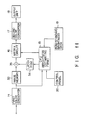
- Fig. 10 is a block diagram showing the third embodiment of the present invention, in which data of a transmitted image signal is input to a terminal 31.
- This image data is temporarily stored in an image memory 32.
- This image memory 3 is a buffer memory having a capacity capable of storing image data having a comparatively significant image area and need not have a capacity of one screen (one frame).
- the input image data is also input to a third color converter 33 and subjected to logarithmic transformation represented by equation (1) by this color converter 33, and the logarithmically transformed image data is input to the CPU 15.
- the signal input to the CPU 15 is processed as in the first embodiment to execute brightness estimation.
- the brightness of an image having only a specific color can be estimated as described above. Therefore, from only a part of an image, brightness estimation can be considerably correctly performed if several types of colors are present. That is, the brightness estimation operation is performed each time image data is input, the brightness correction value ⁇ IH is supplied to a latch 34 when the image memory 32 is almost full with the image data, and an output from the latch 34 is added to an output from a first color converter 14 by an adder 35, thereby executing brightness correction as represented by equation (7).
- data is supplied to a matrix circuit 16 to execute contrast correction as in the first embodiment. In this manner, the brightness estimation and correction can be performed as in the first embodiment to reproduce a precise color image.
- the brightness estimation can be performed using data of only a part of an image and information of an entire image is unnecessary, correct brightness estimation can be performed even when the capacity of the image memory 32 is smaller than a capacity of one frame.
- the brightness estimation operation and the brightness correction operation can be simultaneously performed, the response characteristics can be improved.
- Fig. 5 is a block diagram showing the fourth embodiment as a modification of the embodiment shown in Fig. 4.
- an image memory 32 is arranged after a first color converter 14 so that the color converter 14 can be used in both a brightness estimation operation and a brightness correction operation, thereby simplifying an apparatus.
- a color difference plane is divided into a plurality of blocks, and brightness information is obtained for each block.
- brightness estimation can be executed to some extent to achieve the prescribed object of the present invention.
- color differences are calculated to obtain color difference signals from which an influence of the brightness of an original image (the brightness of a light source) is removed.
- the information about the brightness of the light source can be removed by executing a ratio calculation (division) between the three primary color signals.
- a luminance is compared with a standard luminance in each block on a plane such as a color difference plane, thereby stably estimating brightness information.
- the brightness estimation can be performed by using only a part of an image
- brightness information can be estimated from only a part of transmitted image data or image data of a file to execute brightness correction of the entire image. Therefore, an image memory having a large capacity need not be used, and high-speed processing can be performed.
Applications Claiming Priority (2)
| Application Number | Priority Date | Filing Date | Title |
|---|---|---|---|
| JP123522/90 | 1990-05-14 | ||
| JP2123522A JP3011432B2 (ja) | 1990-05-14 | 1990-05-14 | カラー画像処理装置 |
Publications (2)
| Publication Number | Publication Date |
|---|---|
| EP0457537A2 true EP0457537A2 (de) | 1991-11-21 |
| EP0457537A3 EP0457537A3 (en) | 1992-03-04 |
Family
ID=14862698
Family Applications (1)
| Application Number | Title | Priority Date | Filing Date |
|---|---|---|---|
| EP19910304290 Withdrawn EP0457537A3 (en) | 1990-05-14 | 1991-05-13 | Color image processing apparatus |
Country Status (4)
| Country | Link |
|---|---|
| US (1) | US5278641A (de) |
| EP (1) | EP0457537A3 (de) |
| JP (1) | JP3011432B2 (de) |
| KR (1) | KR940005828B1 (de) |
Cited By (2)
| Publication number | Priority date | Publication date | Assignee | Title |
|---|---|---|---|---|
| EP0833501A2 (de) * | 1996-09-30 | 1998-04-01 | Samsung Electronics Co., Ltd. | Bildqualitätsverbesserungsschaltung und Verfahren dafür |
| US6173560B1 (en) | 1996-11-15 | 2001-01-16 | Kabelschlepp Gmbh | Chain link of different materials and method for its production |
Families Citing this family (33)
| Publication number | Priority date | Publication date | Assignee | Title |
|---|---|---|---|---|
| US6546131B1 (en) * | 1990-12-19 | 2003-04-08 | Canon Kabushiki Kaisha | Image processing method and apparatus for achieving tone reproduction suited to the image |
| DE4310727C2 (de) * | 1992-04-06 | 1996-07-11 | Hell Ag Linotype | Verfahren und Einrichtung zur Analyse von Bildvorlagen |
| DE4309802A1 (de) * | 1993-03-28 | 1994-09-29 | Robert Prof Dr Ing Massen | Produktionsnahe Farbkontrolle mit bildgebenden Sensoren |
| US5495428A (en) * | 1993-08-31 | 1996-02-27 | Eastman Kodak Company | Method for determining color of an illuminant in an image based on histogram data |
| US5450502A (en) * | 1993-10-07 | 1995-09-12 | Xerox Corporation | Image-dependent luminance enhancement |
| JP2702408B2 (ja) * | 1994-07-15 | 1998-01-21 | 日本電気ホームエレクトロニクス株式会社 | 画像変換システム |
| US6043909A (en) * | 1996-02-26 | 2000-03-28 | Imagicolor Corporation | System for distributing and controlling color reproduction at multiple sites |
| US7728845B2 (en) | 1996-02-26 | 2010-06-01 | Rah Color Technologies Llc | Color calibration of color image rendering devices |
| US6445462B2 (en) * | 1996-04-08 | 2002-09-03 | Canon Kabushiki Kaisha | Output control method and apparatus, and output system |
| JP4240236B2 (ja) * | 1996-11-13 | 2009-03-18 | セイコーエプソン株式会社 | 画像処理装置、画像処理方法、画像処理プログラムを記録した媒体および印刷装置 |
| US6351558B1 (en) | 1996-11-13 | 2002-02-26 | Seiko Epson Corporation | Image processing system, image processing method, and medium having an image processing control program recorded thereon |
| WO1999010866A1 (en) * | 1997-08-25 | 1999-03-04 | Imagicolor Corp | A system for distributing and controlling color reproduction at multiple sites |
| WO2000004492A2 (en) | 1998-07-15 | 2000-01-27 | Imation Corp. | Imaging system and method |
| US6807298B1 (en) * | 1999-03-12 | 2004-10-19 | Electronics And Telecommunications Research Institute | Method for generating a block-based image histogram |
| US7262765B2 (en) * | 1999-08-05 | 2007-08-28 | Microvision, Inc. | Apparatuses and methods for utilizing non-ideal light sources |
| US6807301B1 (en) * | 2000-02-25 | 2004-10-19 | Fujitsu Limited | Image production controlling device, image producing device, image production controlling method, and a storage medium |
| US7102648B1 (en) | 2000-04-11 | 2006-09-05 | Rah Color Technologies Llc | Methods and apparatus for calibrating a color display |
| JP4064038B2 (ja) * | 2000-06-09 | 2008-03-19 | 富士フイルム株式会社 | 固体撮像素子を用いた画像取得装置および画像取得方法並びにその方法を実行するためのプログラムを記録した記録媒体 |
| WO2005020130A2 (en) * | 2000-08-18 | 2005-03-03 | Paul Reed Smith Guitars, Limited Partnership | Method of color accentuation with compensation and adjustment |
| US7292369B2 (en) * | 2000-12-28 | 2007-11-06 | Seiko Epson Corporation | Logo data generating method and system |
| US6847377B2 (en) * | 2001-01-05 | 2005-01-25 | Seiko Epson Corporation | System, method and computer program converting pixels to luminance levels and assigning colors associated with luminance levels in printer or display output devices |
| US6950211B2 (en) * | 2001-07-05 | 2005-09-27 | Corel Corporation | Fine moire correction in images |
| JP3992177B2 (ja) * | 2001-11-29 | 2007-10-17 | 株式会社リコー | 画像処理装置、画像処理方法及びコンピュータ・プログラム |
| US20050213125A1 (en) * | 2002-08-19 | 2005-09-29 | Paul Reed Smith Guitars, Limited Partnership | Method of color accentuation with compensation and adjustment |
| US20050212726A1 (en) * | 2004-03-16 | 2005-09-29 | Pioneer Plasma Display Corporation | Method, display apparatus and burn-in reduction device for reducing burn-in on display device |
| JP4359844B2 (ja) * | 2004-11-24 | 2009-11-11 | ノーリツ鋼機株式会社 | フィルムのベース濃度検出方法及びその装置 |
| JP4740602B2 (ja) * | 2005-01-19 | 2011-08-03 | イーストマン コダック カンパニー | オートホワイトバランス装置及びホワイトバランス調整方法 |
| US7894686B2 (en) * | 2006-01-05 | 2011-02-22 | Lsi Corporation | Adaptive video enhancement gain control |
| JP4476955B2 (ja) * | 2006-03-17 | 2010-06-09 | 富士通マイクロエレクトロニクス株式会社 | シェーディング補正回路とその制御方法 |
| KR101018237B1 (ko) * | 2009-02-03 | 2011-03-03 | 삼성전기주식회사 | 단색 영상의 영향을 고려한 자동 화이트 밸런스 조정 장치 및 방법 |
| US20140168253A1 (en) * | 2012-12-18 | 2014-06-19 | Canon Kabushiki Kaisha | Color processing apparatus and method |
| US11386588B2 (en) * | 2016-12-27 | 2022-07-12 | Sony Corporation | Product design system and design image correction apparatus |
| CN113099191B (zh) * | 2021-03-22 | 2023-04-07 | 浙江大华技术股份有限公司 | 一种图像处理方法及装置 |
Citations (3)
| Publication number | Priority date | Publication date | Assignee | Title |
|---|---|---|---|---|
| US4736245A (en) * | 1984-12-12 | 1988-04-05 | Fuji Photo Film Co., Ltd. | Calibration method for color film inspection system |
| EP0369720A2 (de) * | 1988-11-14 | 1990-05-23 | Canon Kabushiki Kaisha | Farbbildverarbeitungsgerät |
| US4975768A (en) * | 1987-12-09 | 1990-12-04 | Canon Kabushiki Kaisha | Image signal processing with suppression of background portion of image |
Family Cites Families (3)
| Publication number | Priority date | Publication date | Assignee | Title |
|---|---|---|---|---|
| EP0145801B1 (de) * | 1983-12-14 | 1987-09-16 | DR.-ING. RUDOLF HELL GmbH | Verfahren und Schaltungsanordnung zur selektiven Korrektur von Farbtönen und Farben |
| DE3629396C2 (de) * | 1986-08-29 | 1993-12-23 | Agfa Gevaert Ag | Verfahren zur elektronischen Bildverarbeitung |
| JPH0722311B2 (ja) * | 1986-11-13 | 1995-03-08 | キヤノン株式会社 | カラ−画像読み取り装置 |
-
1990
- 1990-05-14 JP JP2123522A patent/JP3011432B2/ja not_active Expired - Lifetime
-
1991
- 1991-03-05 US US07/664,726 patent/US5278641A/en not_active Expired - Fee Related
- 1991-05-11 KR KR1019910007609A patent/KR940005828B1/ko not_active IP Right Cessation
- 1991-05-13 EP EP19910304290 patent/EP0457537A3/en not_active Withdrawn
Patent Citations (3)
| Publication number | Priority date | Publication date | Assignee | Title |
|---|---|---|---|---|
| US4736245A (en) * | 1984-12-12 | 1988-04-05 | Fuji Photo Film Co., Ltd. | Calibration method for color film inspection system |
| US4975768A (en) * | 1987-12-09 | 1990-12-04 | Canon Kabushiki Kaisha | Image signal processing with suppression of background portion of image |
| EP0369720A2 (de) * | 1988-11-14 | 1990-05-23 | Canon Kabushiki Kaisha | Farbbildverarbeitungsgerät |
Non-Patent Citations (1)
| Title |
|---|
| IBM TECHNICAL DISCLOSURE BULLETIN vol. 28, no. 3, August 1985, pages 1250 - 1252; 'automatic image brightness scaling' * |
Cited By (3)
| Publication number | Priority date | Publication date | Assignee | Title |
|---|---|---|---|---|
| EP0833501A2 (de) * | 1996-09-30 | 1998-04-01 | Samsung Electronics Co., Ltd. | Bildqualitätsverbesserungsschaltung und Verfahren dafür |
| EP0833501A3 (de) * | 1996-09-30 | 1999-12-01 | Samsung Electronics Co., Ltd. | Bildqualitätsverbesserungsschaltung und Verfahren dafür |
| US6173560B1 (en) | 1996-11-15 | 2001-01-16 | Kabelschlepp Gmbh | Chain link of different materials and method for its production |
Also Published As
| Publication number | Publication date |
|---|---|
| KR910020589A (ko) | 1991-12-20 |
| JP3011432B2 (ja) | 2000-02-21 |
| US5278641A (en) | 1994-01-11 |
| JPH0420072A (ja) | 1992-01-23 |
| KR940005828B1 (ko) | 1994-06-23 |
| EP0457537A3 (en) | 1992-03-04 |
Similar Documents
| Publication | Publication Date | Title |
|---|---|---|
| EP0457537A2 (de) | Farbbildverarbeitungsgerät | |
| US5818975A (en) | Method and apparatus for area selective exposure adjustment | |
| US6919924B1 (en) | Image processing method and image processing apparatus | |
| JP3907783B2 (ja) | 色変換方法 | |
| EP0757473B1 (de) | Bildverarbeitungsgerät und -verfahren | |
| EP0652674B1 (de) | Kaskadenartige Bildverarbeitung mit Histogrammvorhersage | |
| US4931864A (en) | Image forming apparatus which performs gamma correction on the basis of a cumulative frequency distribution produced from a histogram of image data representing a selected area of an image | |
| EP1311111A2 (de) | Verfahren und Vorrichtung zur Korrektur des Weissabgleichs, Verfahren zur Dichtekorrektur und Programmaufzeichnungsmedium | |
| JP2001298619A (ja) | 画像処理方法及び画像処理装置 | |
| US7409082B2 (en) | Method, apparatus, and recording medium for processing image data to obtain color-balance adjusted image data based on white-balance adjusted image data | |
| US6002806A (en) | Method of and apparatus for correcting color | |
| JP2002222413A (ja) | 自動彩度強調 | |
| JP3728744B2 (ja) | プリント方法及び装置 | |
| US7034959B1 (en) | Method, apparatus and recording medium for image processing | |
| US6459500B1 (en) | Image processing apparatus | |
| JP2002125130A (ja) | 画像処理装置、画像処理方法および画像処理プログラムを記録した記録媒体 | |
| US5949962A (en) | Method for calculating color correction conditions, a method for determining an exposure amount for printing, an image processing apparatus, a printing exposure apparatus and a storage medium | |
| US20040036899A1 (en) | Image forming method, image processing apparatus, print producing apparatus and memory medium | |
| EP0578203B1 (de) | Verfahren und Vorrichtung zur Erzeugung von Bilddaten aus Kaskadenartigen photographischen Bildherstellungssystemen | |
| JP3408770B2 (ja) | 画像処理装置 | |
| US5406394A (en) | Color reproducing method used in an image data processing system comprising independent input and output devices | |
| JPH11191871A (ja) | 画像処理装置 | |
| JP2003209856A (ja) | ホワイトバランス補正方法 | |
| JP2000333185A (ja) | 撮影装置並びにホワイトバランス調整方法および装置 | |
| EP0940773B1 (de) | Bilverarbeitungsverfahren und -vorrichtung |
Legal Events
| Date | Code | Title | Description |
|---|---|---|---|
| PUAI | Public reference made under article 153(3) epc to a published international application that has entered the european phase |
Free format text: ORIGINAL CODE: 0009012 |
|
| 17P | Request for examination filed |
Effective date: 19910524 |
|
| AK | Designated contracting states |
Kind code of ref document: A2 Designated state(s): DE FR GB |
|
| PUAL | Search report despatched |
Free format text: ORIGINAL CODE: 0009013 |
|
| AK | Designated contracting states |
Kind code of ref document: A3 Designated state(s): DE FR GB |
|
| 17Q | First examination report despatched |
Effective date: 19940304 |
|
| STAA | Information on the status of an ep patent application or granted ep patent |
Free format text: STATUS: THE APPLICATION IS DEEMED TO BE WITHDRAWN |
|
| 18D | Application deemed to be withdrawn |
Effective date: 19940715 |