EP0456554B1 - Elément conducteur électrique et procédé de fabrication de celui-ci - Google Patents
Elément conducteur électrique et procédé de fabrication de celui-ci Download PDFInfo
- Publication number
- EP0456554B1 EP0456554B1 EP91401141A EP91401141A EP0456554B1 EP 0456554 B1 EP0456554 B1 EP 0456554B1 EP 91401141 A EP91401141 A EP 91401141A EP 91401141 A EP91401141 A EP 91401141A EP 0456554 B1 EP0456554 B1 EP 0456554B1
- Authority
- EP
- European Patent Office
- Prior art keywords
- flame
- electrically conducting
- base
- component according
- retarding substance
- Prior art date
- Legal status (The legal status is an assumption and is not a legal conclusion. Google has not performed a legal analysis and makes no representation as to the accuracy of the status listed.)
- Expired - Lifetime
Links
Images
Classifications
-
- H—ELECTRICITY
- H01—ELECTRIC ELEMENTS
- H01Q—ANTENNAS, i.e. RADIO AERIALS
- H01Q17/00—Devices for absorbing waves radiated from an antenna; Combinations of such devices with active antenna elements or systems
-
- Y—GENERAL TAGGING OF NEW TECHNOLOGICAL DEVELOPMENTS; GENERAL TAGGING OF CROSS-SECTIONAL TECHNOLOGIES SPANNING OVER SEVERAL SECTIONS OF THE IPC; TECHNICAL SUBJECTS COVERED BY FORMER USPC CROSS-REFERENCE ART COLLECTIONS [XRACs] AND DIGESTS
- Y10—TECHNICAL SUBJECTS COVERED BY FORMER USPC
- Y10S—TECHNICAL SUBJECTS COVERED BY FORMER USPC CROSS-REFERENCE ART COLLECTIONS [XRACs] AND DIGESTS
- Y10S428/00—Stock material or miscellaneous articles
- Y10S428/92—Fire or heat protection feature
-
- Y—GENERAL TAGGING OF NEW TECHNOLOGICAL DEVELOPMENTS; GENERAL TAGGING OF CROSS-SECTIONAL TECHNOLOGIES SPANNING OVER SEVERAL SECTIONS OF THE IPC; TECHNICAL SUBJECTS COVERED BY FORMER USPC CROSS-REFERENCE ART COLLECTIONS [XRACs] AND DIGESTS
- Y10—TECHNICAL SUBJECTS COVERED BY FORMER USPC
- Y10S—TECHNICAL SUBJECTS COVERED BY FORMER USPC CROSS-REFERENCE ART COLLECTIONS [XRACs] AND DIGESTS
- Y10S428/00—Stock material or miscellaneous articles
- Y10S428/92—Fire or heat protection feature
- Y10S428/921—Fire or flameproofing
-
- Y—GENERAL TAGGING OF NEW TECHNOLOGICAL DEVELOPMENTS; GENERAL TAGGING OF CROSS-SECTIONAL TECHNOLOGIES SPANNING OVER SEVERAL SECTIONS OF THE IPC; TECHNICAL SUBJECTS COVERED BY FORMER USPC CROSS-REFERENCE ART COLLECTIONS [XRACs] AND DIGESTS
- Y10—TECHNICAL SUBJECTS COVERED BY FORMER USPC
- Y10T—TECHNICAL SUBJECTS COVERED BY FORMER US CLASSIFICATION
- Y10T428/00—Stock material or miscellaneous articles
- Y10T428/24—Structurally defined web or sheet [e.g., overall dimension, etc.]
- Y10T428/24802—Discontinuous or differential coating, impregnation or bond [e.g., artwork, printing, retouched photograph, etc.]
-
- Y—GENERAL TAGGING OF NEW TECHNOLOGICAL DEVELOPMENTS; GENERAL TAGGING OF CROSS-SECTIONAL TECHNOLOGIES SPANNING OVER SEVERAL SECTIONS OF THE IPC; TECHNICAL SUBJECTS COVERED BY FORMER USPC CROSS-REFERENCE ART COLLECTIONS [XRACs] AND DIGESTS
- Y10—TECHNICAL SUBJECTS COVERED BY FORMER USPC
- Y10T—TECHNICAL SUBJECTS COVERED BY FORMER US CLASSIFICATION
- Y10T442/00—Fabric [woven, knitted, or nonwoven textile or cloth, etc.]
- Y10T442/20—Coated or impregnated woven, knit, or nonwoven fabric which is not [a] associated with another preformed layer or fiber layer or, [b] with respect to woven and knit, characterized, respectively, by a particular or differential weave or knit, wherein the coating or impregnation is neither a foamed material nor a free metal or alloy layer
- Y10T442/2418—Coating or impregnation increases electrical conductivity or anti-static quality
- Y10T442/2426—Elemental carbon containing
-
- Y—GENERAL TAGGING OF NEW TECHNOLOGICAL DEVELOPMENTS; GENERAL TAGGING OF CROSS-SECTIONAL TECHNOLOGIES SPANNING OVER SEVERAL SECTIONS OF THE IPC; TECHNICAL SUBJECTS COVERED BY FORMER USPC CROSS-REFERENCE ART COLLECTIONS [XRACs] AND DIGESTS
- Y10—TECHNICAL SUBJECTS COVERED BY FORMER USPC
- Y10T—TECHNICAL SUBJECTS COVERED BY FORMER US CLASSIFICATION
- Y10T442/00—Fabric [woven, knitted, or nonwoven textile or cloth, etc.]
- Y10T442/20—Coated or impregnated woven, knit, or nonwoven fabric which is not [a] associated with another preformed layer or fiber layer or, [b] with respect to woven and knit, characterized, respectively, by a particular or differential weave or knit, wherein the coating or impregnation is neither a foamed material nor a free metal or alloy layer
- Y10T442/2631—Coating or impregnation provides heat or fire protection
Definitions
- the invention relates to an electrically conductive element intended more particularly for the production of elements which absorb electromagnetic waves, in particular radar waves.
- the invention also relates to a method of manufacturing such an electrically conductive surface element.
- electromagnetic wave absorbing elements for the constitution of facades.
- Such absorbers are for example obtained by filling a frame similar to a cassette, alternately by insulating elements in mineral wool and electrically conductive elements, the laminated structure thus obtained being fixed to the building by means of the frame.
- EP-A-414 613 is described a more industrial method of manufacturing such absorbing elements obtained by stacking strips of mineral wool between which are inserted conductive elements electrics obtained for example by impregnating graphite with a nonwoven or constituted by a nonwoven of carbon fibers, the assembly then being cut by vertical cutting and applied to a support strip.
- the lamellar structure can only be obtained on the condition of using binders with mineral wool, binders which lead to products of a combustible nature. Character reinforced by the very combustible nature of the conductive material which permeates the conductive elements.
- the object of the invention is to provide an electrically conductive element making it possible to constitute, with an economical manufacturing process, elements which absorb electromagnetic waves, in particular radar waves, which are non-combustible, possibly satisfying the fire resistance tests required for construction materials.
- Class A according to DIN 4102. This object is achieved by the manufacturing process claimed in claim 10 and by the product claimed in claim 1.
- the element according to the invention is therefore distinguished from the prior art by the presence of a flame retardant substance on the nonwoven base.
- the absorbers constructed with such an element satisfy the fire resistance tests allowing their classification as non-combustible combustion materials of class A in accordance with DIN 4102.
- the added flame retardant substance compensates for degradations in fire behavior due to the application of a conductive material fuel and the use of binders.
- the quantity of conductive material applied no longer has to be limited as a function of the desired fire behavior and can therefore be chosen only as a function of the expected absorption behavior.
- the application of the electromagnetically active conductive material by a printing process also offers the advantage of making industrial production possible with particularly close tolerances of the quantities applied, which results in the possibility of obtaining very absorbers. selective.
- the techniques of application by immersion, deposit with a brush or doctor blade or even by spraying do not allow a suitable and constant distribution of the material, under the usual industrial conditions.
- printing process is preferably meant a screen printing process, the conductive material - in this case preferably carbon black or graphite - being dispersed in a paint base.
- the conductive material in this case preferably carbon black or graphite - being dispersed in a paint base.
- the base of the element is made of a nonwoven, preferably of the veil type of glass fibers, which is particularly effective for the constitution of an absorber with a lamellar structure.
- layers alternating strips of mineral wool and glass fiber veil will be fixed in particular by gluing on a flat support.
- a flame-retardant substance it is more particularly advantageous to use a material which exhibits an endothermic modification of its structure before reaching the maximum admissible temperature.
- Accumulators with a high content of water of crystallization are particularly suitable for this purpose. In the event of a fire, at critical temperatures, release and vaporization of the water of crystallization is observed; a significant slowing effect is then obtained which can be determined with precision over time.
- Aluminum hydroxide is mainly suitable for this purpose and preferably finds its application with an extremely low content of binder, less than 5% on the basis of the dry weight. Can also be used as accumulators hydrated aluminum oxide and dehydrated sodium sulfate.
- the non-woven base fireproofing is preferably carried out by impregnation before applying the conductive material.
- the inorganic flame retardant is thus applied in a relatively large amount in a separate operation.
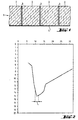
- FIG. 1 represents a planar element produced in the form of a mat having a layered structure formed by layers 2 of mineral wool alternating with narrower strips 3 of an electrically conductive element according to the invention, the assembly forming a system with several layers absorbing the waves scattered by a radar.
- the insulating layers 2 and the conductive strips 3 can be applied separately to a building facade, by gluing, pegging, wedging or in any other way. In the present case, however, they are deposited on a sheet 4, for example a sheet of reinforced aluminum.
- the layered structure 1 is arranged in a cassette-shaped frame, not shown here, which is used for fixing between the masonry and the outer face constituted by a glass plate, or any other cladding plate in any other material.
- the electromagnetic waves reaching the outer cladding plate penetrate largely without reflection through the cladding plate and are substantially absorbed in the layered structure. This results in a weak reflection on the facade.
- the strips 3 advantageously consist of a veil of glass fibers forming the base of the electrically conductive element.
- the electromagnetic conductive substance and a flame-retardant substance are incorporated in the glass fibers, which are decisive substances for damping the reflection of the facade.
- the base is preferably made of a veil of glass fibers but other veils and other materials, for example a thin sheet, can also be used.
- carbon black or graphite or another electrically conductive material is preferably used. These materials must be dispersible.
- the distances between two conductive elements 3 are chosen as a function of the wavelength of the electromagnetic waves to be absorbed, so that there is within the element, absorption, in particular absorption by resonance of the penetrating waves. Furthermore, the degree of absorption depends very closely on the distribution and the quantity of the conductive material.
- a regular distribution of the conductive material on the planar element with a very narrow application tolerance is obtained by a printing process. In this case, a fast-setting colored dispersion, enriched in material, is used as ink. conductive, for example in carbon black.
- the screen printing process is particularly suitable for meeting close tolerances.
- a printing ink specially suitable for screen printing contains organic substances such as emulsifiers, binders and fillers. The printing process thus leads to a relatively significant organic enrichment of the planar element, which certainly results in a layered structure having a high absorption power, but can simultaneously lead to a degradation of the fire resistance.
- a flame retardant substance is applied in an amount such that it forms on the web, an insulating layer which improves the fire content.
- aluminum hydroxide and an extremely low binder content is suitable as a substance.
- Aluminum hydroxide is an accumulation material with a high content of water of crystallization, released in the event of fire.
- hydrated aluminum oxide, hydrated sodium metasilicate or dehydrated sodium sulphate can also be used.
- the process of applying the ink dispersion containing carbon black is carried out in an additional coating operation. .
- the screen printing process leads to an economical consumption of carbon black with low application tolerances.
- the dispersion of liquid ink consists of 70% water and 30% of solids formed by 5% of carbon black, 5% of dispersion auxiliaries and 20% of binder and filler.
- Chalk can for example be chosen as a filler. In this case, it was possible to obtain an excellent absorption behavior of the constant radar throughout the surface of the conducting element.
- the diagram in Figure 2 shows the depreciation of the reflection of microwaves at 600 MHz as a function of the quantity of carbon black incorporated into a veil of glass fibers, previously flame retarded, with a basis weight of 60 g per m 2 .
- This diagram shows very clearly that for elements comprising a quantity of carbon black of 9 to 16 g per m 2 , a very good damping of the reflection, of -11.5 to -15 dB, can be obtained.
- the optimal range is at an applied amount of carbon black of 10 to 12 g per m 2 .
- the damping in reflection of the element in question thus measured in a waveguide gives the direct correlation with the damping of reflection desired of a facade element, for the usual radar frequencies of 1.03 to 1.09 GHz. In this way, a reflection damping of -13.5 to -15 dB could be obtained.
- the conductive material for example carbon black
- an ink dispersion with organic substances emulsifiers and binders
- a prior coating of the glass fiber veil by means of an accumulating material releasing water in the event of fire makes it possible to achieve, for the planar element, favorable properties as regards incombustibility.
- a layered structure formed by means of this element then corresponds to the class of building materials A according to DIN 4102.
- the particular effect obtained by means of the measures in accordance with the invention can be qualified physically as a combined interference and absorption effect for electromagnetic waves. It can also be attributed essentially to an appropriate incorporation of the carbon black particles within the particles forming the ink dispersion and to the conductivity structure which is thus established.
- the screen printing technique leads to a uniform and economical distribution of carbon black particles within the ink dispersion on the veil of glass fibers. This results in a coating with carbon black with very narrow application tolerances and thus optimal damping of the reflection.
- the reproducibility of planar conductive elements having defined absorption properties is an advantage here.
Landscapes
- Shielding Devices Or Components To Electric Or Magnetic Fields (AREA)
- Building Environments (AREA)
- Aerials With Secondary Devices (AREA)
- Parts Printed On Printed Circuit Boards (AREA)
- Laminated Bodies (AREA)
- Fixed Capacitors And Capacitor Manufacturing Machines (AREA)
- Thermistors And Varistors (AREA)
- Encapsulation Of And Coatings For Semiconductor Or Solid State Devices (AREA)
- Chemical Or Physical Treatment Of Fibers (AREA)
Description
- L'invention a pour objet un élément conducteur électrique destiné plus particulièrement à la réalisation d'éléments absorbeurs d'ondes électromagnétiques notamment d'ondes radar. L'invention a également pour objet un procédé de fabrication d'un tel élément de surface conducteur électrique.
- Près des aéroports, le radio repérage nécessaire au contrôle aérien est souvent perturbé par les échos parasites dus à la réflexion des ondes radar par les façades des bâtiments du voisinage. Au sol, ces échos parasites peuvent être filtrés mais les installations nécessaires à ce filtrage sont trop encombrantes pour être montées à bord des appareils. C'est pourquoi il est souhaitable de supprimer dans une large mesure la réflexion des ondes électromagnétiques par les façades.
- Pour ce faire, il est connu d'utiliser pour la constitution des façades des éléments absorbeurs d'ondes électromagnétiques. De tels absorbeurs sont par exemple obtenus en remplissant un cadre semblable à une cassette, en alternance par des éléments isolants en laine minérale et des éléments conducteurs électriques, la structure lamellée ainsi obtenue étant fixée au bâtiment par l'intermédiaire du cadre. Dans la demande de brevet EP-A-414 613 est décrit un procédé plus industriel de fabrication de tels éléments absorbeurs obtenus en empilant des bandes en laine minérale entre lesquelles sont intercalés des éléments conducteurs électriques obtenus par exemple par imprégnation de graphite d'un non-tissé ou constitués par un non-tissé en fibres de carbone, l'ensemble étant ensuite débité par coupe verticale et appliqué sur une bande-support.
- Pour obtenir une bonne sélectivité de l'absorption, il importe de respecter, en fonction de la longueur d'onde à absorber, un rapport précis entre les épaisseurs relatives des éléments isolants et des éléments conducteurs électriques mais aussi un parfait dosage de la quantité de matière conductrice électromagnétiquement active appliquée, dosage qui ne peut être réalisé que de façon semi-artisanale. Par ailleurs, la structure lamellaire ne peut être obtenue qu'à la condition d'utiliser des liants avec la laine minérale, liants qui conduisent à des produits à caractère combustible. Caractère renforcé par la nature combustible même de la matière conductrice qui imprègne les éléments conducteurs.
- L'invention a pour but un élément conducteur électrique permettant de constituer avec un procédé de fabrication économique des éléments absorbeurs d'ondes électromagnétiques, notamment d'ondes radar, non combustibles, satisfaisant éventuellement les tests de tenue au feu exigés pour les matériaux de construction de classe A selon la norme DIN 4102. Ce but est atteint par le procédé de fabrication revendiqué en revendication 10 et par le produit revendiqué en revendication 1.
- L'élément conforme à l'invention se distingue donc de l'art antérieur par la présence d'une substance ignifuge sur la base en non-tissé. Les absorbeurs construits avec un tel élément satisfont les tests de tenue au feu permettant leur classement comme matériaux de combustion incombustible de classe A conformément à la norme DIN 4102. La substance ignifuge ajoutée compense les dégradations de comportement au feu dues à l'application d'une matière conductrice combustible et à l'utilisation de liants. De plus, la quantité de matière conductrice appliquée n'a plus à être limitée en fonction du comportement au feu désiré et peut de ce fait être choisie uniquement en fonction du comportement d'absorption espéré.
- L'application de la matière conductrice électromagnétiquement active par un procédé d'impression offre de plus l'avantage de rendre possible une fabrication industrielle avec des tolérances particulièrement étroites des quantités appliquées, d'où il résulte la possibilité d'obtention d'absorbeurs très sélectifs. D'après l'expérience de la demanderesse, les techniques d'application par immersion, dépôt au pinceau ou à la racle ou encore par pulvérisation ne permettent pas une répartition convenable et constante de la matière, dans les conditions industrielles usuelles.
- L'emploi d'un procédé d'impression n'est cependant rendu possible que grâce à la présence de la substance ignifuge qui compense la dégradation de la tenue au feu entraînée inéluctablement par la présence de produits organiques dans les encres d'impression. Ainsi, en améliorant le comportement au feu de l'absorbeur, on peut respecter des tolérances d'application de la matière conductrice plus étroites et, par un effet de synergie, améliorer indirectement la capacité d'absorption des ondes électromagnétiques.
- Par procédé d'impression, on entend de préférence un procédé sérigraphique, la matière conductrice - dans ce cas de préférence du noir de carbone ou du graphite - étant dispersée dans une base de peinture. Dans ces conditions, il est possible d'appliquer la matière conductrice selon une quantité comprise entre 9 à 16 g par mètre carré et de préférence de 10 à 12 g par mètre-carré, quantité optimale dans le cas visé d'une absorption préférentielle des ondes radar.
- La base de l'élément est faite d'un non-tissé, de préférence du type voile de fibres de verre, ce qui est particulièrement efficace pour la constitution d'un absorbeur à structure lamellaire. En l'occurence, des couches alternées de bandes en laine minérale et de voile de fibres de verre seront fixés notamment par collage sur un support plat.
- A titre de substance ignifuge, il est plus particulièrement avantageux d'utiliser une matière qui présente une modification endothermique de sa structure avant d'atteindre la température maximale admissible. Les matières accumulatrices à haute teneur en eau de cristallisation conviennent particulièrement à cet effet. En cas d'incendie, à des températures critiques, on observe une libération et une vaporisation de l'eau de cristallisation ; on obtient alors un effet de ralentissement sensible qui peut être déterminé avec précision dans le temps. L'hydroxyde d'aluminium convient principalement dans ce but et trouve de préférence son application avec une teneur en liant extrêmement faible, inférieure à 5 % sur la base du poids sec. Peuvent être également employées comme matières accumulatrices l'oxyde d'aluminium hydraté et le sulfate de sodium déshydraté.
- L'ignifugation de la base en non-tissé est effectuée de préférence par imprégnation avant de procéder à l'application de la matière conductrice. La substance ignifuge inorganique est appliquée ainsi en quantité relativement grande, au cours d'une opération distincte.
- Un exemple d'application de l'invention est décrit de façon purement schématique en référence aux dessins annexés qui représentent :
- . figure 1 : la structure d'un absorbeur du type d'un système à plusieurs couches,
- . figure 2 : un diagramme de l'amortissement en réflexion en fonction de la quantité de matière conductrice appliquée, en l'occurrence du noir de carbone.
- La figure 1 représente un élément plan réalisé en forme de mat ayant une structure en couches formée de couches 2 de laine minérale alternant avec des bandes plus étroites 3 d'un élément conducteur électrique selon l'invention, l'ensemble formant un système à plusieurs couches absorbant les ondes diffusées par un radar. Les couches isolantes 2 et les bandes conductrices 3 peuvent être appliquées séparément sur une façade de bâtiment, par collage, chevillage, coincement ou de toute autre manière. Dans le cas présent, elles sont cependant déposées sur une nappe 4, par exemple une feuille d'aluminium armée. Pour l'équipement d'une façade, la structure en couches 1 est disposée dans un cadre en forme de cassette, ici non représenté, qui sert à la fixation entre la maçonnerie et la face extérieure constituée par une plaque en verre, ou toute autre plaque de bardage en toute autre matière.
- Les ondes électromagnétiques atteignant la plaque de bardage extérieure pénètrent largement sans réflexion à travers la plaque de bardage et sont sensiblement absorbées dans la structure en couches. Il en résulte une faible réflexion sur la façade.
- Les bandes 3 sont constituées avantageusement d'un voile de fibres de verre formant la base de l'élément conducteur électrique. La substance conductrice électromagnétique et une substance ignifuge sont incorporées dans les fibres de verre, substances décisives pour l'amortissement de la réflexion de la façade.
- La base est de préférence faite d'un voile de fibres de verre mais d'autres voiles et d'autres matières, par exemple une feuille mince, peuvent être également utilisés.
- Comme matière conductrice, on utilise de préférence le noir de carbone ou le graphite ou une autre matière conductrice d'électricité. Ces matières doivent être dispersables.
- Dans la structure en couches, les distances entre deux éléments conducteurs 3 sont choisies en fonction de la longueur d'onde des ondes électromagnétiques à absorber, pour qu'il y ait au sein de l'élément, une absorption, en particulier une absorption par résonance des ondes ayant pénétré. Par ailleurs, le degré d'absorption dépend très étroitement de la répartition et de la quantité de la matière conductrice. Une répartition régulière de la matière conductrice sur l'élément plan avec une tolérance d'application fort étroite, est obtenue par un procédé d'impression. En l'occurrence, on utilise comme encre une dispersion colorée à prise rapide, enrichie en matière conductrice, par exemple en noir de carbone. Le procédé sérigraphique convient particulièrement pour le respect de tolérances étroites. Une encre pour l'impression convenant spécialement pour la sérigraphie contient des substances organiques tels des émulsionnants, liants et charges. Le procédé par impression conduit ainsi à un enrichissement organique relativement important de l'élément plan, ce qui a certes pour conséquence une structure en couches ayant un haut pouvoir d'absorption, mais peut simultanément conduire à une dégradation de la tenue au feu.
- Ceci est compensé par le fait qu'au cours d'une opération supplémentaire, en particulier avant l'application de la matière conductrice, une substance ignifuge est appliquée en une quantité telle qu'il se forme sur le voile, une couche isolante qui améliore la teneur au feu. En particulier, l'hydroxyde d'aluminium et une teneur en liant extrêmement faible, avantageusement inférieure à 5 % en poids sur base sèche, convient comme substance. L'hydroxyde d'aluminium constitue une matière d'accumulation présentant une haute teneur en eau de cristallisation, dégagée en cas d'incendie. Comme matière à haute teneur en eau de cristallisation, on peut utiliser aussi l'oxyde d'aluminium hydraté, le métasilicate de sodium hydraté ou le sulfate de sodium déshydraté.
- Après avoir revêtu la base, à savoir le voile de fibres de verre, au moyen de la substance ignifuge, on procède, au cours d'une opération de revêtement supplémentaire, à l'application de la dispersion d'encre contenant du noir de carbone. Le procédé sérigraphique conduit à une consommation économe du noir de carbone avec de faibles tolérances d'application.
- Selon une variante, la dispersion d'encre liquide est constituée par 70 % d'eau et 30 % de solides formés par 5 % de noir de carbone, 5 % d'auxiliaires de dispersion et 20 % de liant et charge. La craie peut par exemple être choisie comme charge. Dans ce cas, on a pu obtenir un excellent comportement d'absorption du radar constant dans toute la surface de l'élément conducteur.
- Le diagramme de la figure 2 montre l'amortissement de la réflexion de micro-ondes à 600 MHz en fonction de la quantité de noir de carbone incorporée à un voile de fibres de verre, préalablement ignifugé, d'un grammage de 60 g par m2. Ce diagramme montre très clairement que pour des éléments comportant une quantité de noir de carbone de 9 à 16g par m2, un très bon amortissement de la réflexion, de -11,5 à -15 dB, peut être obtenu. Le domaine optimal se situe à une quantité appliquée de noir de carbone de 10 à 12 g par m2. L'amortissement en réflexion de l'élément en question ainsi mesuré dans un guide d'ondes donne la corrélation directe avec l'amortissement de réflexion souhaité d'un élément de façade, pour les fréquences radar habituelles de 1,03 à 1,09 GHz. De cette façon, un amortissement de réflexion de -13,5 à -15 dB a pu être obtenu.
- Des tolérances d'application étroites sont atteintes grâce à une application de la matière conductrice, par exemple le noir de carbone, suivant une technique d'impression. On utilise dans ce cas une dispersion d'encre avec des substances organiques (émulsionnants et liants). Un revêtement préalable du voile de fibres de verre au moyen d'une matière accumulatrice dégageant de l'eau en cas d'incendie, permet d'atteindre, pour l'élément plan, des propriétés favorables quant à l'incombustibilité. Une structure en couches formée au moyen de cet élément correspond alors à la classe des matériaux de construction A suivant la norme DIN 4102.
- L'effet particulier obtenu grâce aux mesures conformes à l'invention, peut être qualifié physiquement d'effet combiné d'interférence et d'absorption pour les ondes électromagnétiques. Il peut être aussi attribué essentiellement à une incorporation appropriée des particules de noir de carbone au sein des particules formant la dispersion d'encre et à la structure de conductibilité qui s'établit ainsi. La technique sérigraphique conduit quant à elle à une répartition uniforme et économe des particules de noir de carbone au sein de la dispersion d'encre sur le voile de fibres de verre. Il en résulte un revêtement par du noir de carbone avec des tolérances d'application fort étroites et ainsi un amortissement optimal de la réflexion. La reproductibilité des éléments plans conducteurs possèdant des propriétés d'absorption définies, constitue en l'occurrence un avantage.
Claims (12)
- Elément conducteur électrique (3) pour un absorbeur d'ondes électromagnétiques dans la gamme des ondes très courtes, destiné à la configuration de façades, comportant un voile constitué d'un non-tissé, servant de base et une couche d'une matière electriquement conductrice, caractérisé en ce que le non-tissé est revêtu d'une substance ignifuge, la matière électriquement conductrice étant appliquée comme couche homogène suivant un procédé d'impression sur la face du voile revêtu de la substance ignifuge.
- Elément conducteur électrique suivant la revendication 1, caractérisé en ce que la matière conductrice, formée du noir de carbone, du graphite ou analogue, est appliquée sur le voile revêtu d'une substance ignifuge par un procédé sérigraphique.
- Elément conducteur électrique suivant la revendication 1 ou 2, caractérisé en ce que la matière conductrice est appliquée conjointement avec une dispersion adhésive sur la base.
- Elément conducteur électrique suivant la revendication 3, caractérisé en ce que la dispersion adhésive est formée par des matières organiques, en particulier des emulsionnants, des liants et des charges.
- Elément conducteur électrique suivant quelconque des revendications précédentes, caractérisé en ce que la base est formée par un voile de fibres de verre.
- Elément conducteur électrique suivant quelconque des revendications précédentes, caractérisé en ce que la base est revêtue d'une matière modifiant de façon endothermique sa structure, avant d'atteindre une température maximale admissible, comme substance ignifuge.
- Elément conducteur électrique suivant la revendication 6, caractérisé en ce que la substance ignifuge est une matière accumulatrice ayant une haute teneur en eau de cristallisation.
- Elément conducteur électrique suivant la revendication 7, caractérisé en ce que la substance ignifuge est de l'hydroxyde d'aluminium, de l'oxyde d'aluminium hydraté, du métallicate de sodium hydraté ou du sulfate de sodium déshydraté.
- Elément conducteur électrique suivant la revendication 8, caractérisé en ce que la substance ignifuge a une faible teneur en liant, de préférance inférieure à 5 % à la base du poids sec.
- Procédé de fabrication d'un élément conducteur électrique (3), suivant les revendications 1 à 9, comportant une étape de revêtement d'un voile constitue d'un non-tissé servant de base, avec une matière électriquement conductrice caractérisé en ce que la base est préalablement revêtue d'une substance ignifuge avant l'application de la matière conductrice.
- Procédé suivant la revendication 10, caractérisé en ce qu'après le revêtement de la base au moyen de la substance ignifuge, la matière conductrice est appliquée dans une dispersion adhésive.
- Procédé suivant la revendication 10 ou 11, caractérisé en ce que le facteur de noir de carbone est appliqué sur la base en une quantité de 9 à 16 et de préférence de 10 à 12 g par m2.
Applications Claiming Priority (2)
| Application Number | Priority Date | Filing Date | Title |
|---|---|---|---|
| DE4014453A DE4014453C2 (de) | 1990-05-06 | 1990-05-06 | Elektrisch leitfähiges Flächenelement sowie Verfahren zur Herstellung desselben |
| DE4014453 | 1990-05-06 |
Publications (3)
| Publication Number | Publication Date |
|---|---|
| EP0456554A2 EP0456554A2 (fr) | 1991-11-13 |
| EP0456554A3 EP0456554A3 (en) | 1993-09-29 |
| EP0456554B1 true EP0456554B1 (fr) | 1997-03-12 |
Family
ID=6405772
Family Applications (1)
| Application Number | Title | Priority Date | Filing Date |
|---|---|---|---|
| EP91401141A Expired - Lifetime EP0456554B1 (fr) | 1990-05-06 | 1991-04-30 | Elément conducteur électrique et procédé de fabrication de celui-ci |
Country Status (8)
| Country | Link |
|---|---|
| US (1) | US5223327A (fr) |
| EP (1) | EP0456554B1 (fr) |
| JP (1) | JP2971168B2 (fr) |
| AT (1) | ATE150216T1 (fr) |
| CA (1) | CA2041823A1 (fr) |
| DE (2) | DE4014453C2 (fr) |
| DK (1) | DK0456554T3 (fr) |
| ES (1) | ES2099144T3 (fr) |
Families Citing this family (12)
| Publication number | Priority date | Publication date | Assignee | Title |
|---|---|---|---|---|
| DE4215954A1 (de) * | 1992-02-04 | 1993-08-05 | Rheinhold & Mahla Ag | Absorber fuer elektromagnetische wellen |
| US5840383A (en) * | 1996-02-12 | 1998-11-24 | Bgf Industries, Inc. | Electromagnetic wave reflective fabric |
| DE19610197C1 (de) * | 1996-03-15 | 1997-08-28 | Daimler Benz Aerospace Ag | Fassadenaufbau von Gebäuden |
| JP2000516018A (ja) * | 1996-08-07 | 2000-11-28 | シーメンス アクチエンゲゼルシヤフト | 絶縁スリーブ形成用の低導電性材料 |
| IT1289932B1 (it) * | 1997-02-19 | 1998-10-19 | Indutex S R L | Tessuto non tessuto presentante caratteristiche antistatiche e utilizzabile in vari campi |
| DE19717682A1 (de) * | 1997-04-28 | 1998-10-29 | Helmut Dr Reichelt | Beschichtungsmaterial für Strahlungsflächen zur Erzeugung elektromagnetischer Wellen und Verfahren zu dessen Herstellung |
| DE19747622A1 (de) * | 1997-10-28 | 1999-04-29 | Gruenzweig & Hartmann | Dämmplatten mit einer Abschirmung gegen elektromagnetische Felder |
| JP3983404B2 (ja) * | 1999-01-13 | 2007-09-26 | 本田技研工業株式会社 | レーダ搭載車両用ゲート |
| DE19942882B4 (de) * | 1999-09-08 | 2005-11-03 | Sto Ag | Armierung |
| US7686061B2 (en) * | 2002-04-24 | 2010-03-30 | Overhead Door Corporation | Winding assembly for door counterbalance system |
| US7846546B2 (en) * | 2005-09-20 | 2010-12-07 | Ube Industries, Ltd. | Electrically conducting-inorganic substance-containing silicon carbide-based fine particles, electromagnetic wave absorbing material and electromagnetic wave absorber |
| CN108716063A (zh) * | 2018-06-25 | 2018-10-30 | 中原工学院 | 一种导电阻燃抗菌纤维水刺非织造防屏蔽材料的制备方法 |
Family Cites Families (28)
| Publication number | Priority date | Publication date | Assignee | Title |
|---|---|---|---|---|
| DE1234281B (fr) * | 1957-12-13 | |||
| US4038660A (en) * | 1975-08-05 | 1977-07-26 | The United States Of America As Represented By The Secretary Of The Army | Microwave absorbers |
| DE2750776C3 (de) * | 1977-11-14 | 1980-06-04 | Precitronic Gesellschaft Fuer Feinmechanik Und Electronic Mbh, 2000 Hamburg | Azimutal richtbare Abschußvorrichtung |
| US4327364A (en) * | 1978-12-22 | 1982-04-27 | Rockwell International Corporation | Apparatus for converting incident microwave energy to thermal energy |
| CH653290A5 (de) * | 1979-05-29 | 1985-12-31 | Ebnoether Ag | Nicht textiles wandbekleidungsmaterial. |
| GB2058469B (en) * | 1979-08-31 | 1983-12-14 | Plessey Co Ltd | Radiation-absorbing materials |
| DE3024888A1 (de) * | 1980-07-01 | 1982-02-04 | Bayer Ag, 5090 Leverkusen | Verbundmaterial zur abschirmung elektromagnetischer strahlung |
| US4347284A (en) * | 1980-11-03 | 1982-08-31 | Hiraoka & Co., Ltd. | White cover sheet material capable of reflecting ultraviolet rays |
| JPS6146099A (ja) * | 1984-08-10 | 1986-03-06 | 株式会社ブリヂストン | 電磁波反射体 |
| US4606848A (en) * | 1984-08-14 | 1986-08-19 | The United States Of America As Represented By The Secretary Of The Army | Radar attenuating paint |
| DE3507889A1 (de) * | 1985-03-06 | 1986-09-11 | Clouth Gummiwerke AG, 5000 Köln | Mit einer beschichtung versehenes objekt |
| EP0193636A1 (fr) * | 1985-03-08 | 1986-09-10 | Konrad Hornschuch Aktiengesellschaft | Bande textile réflectrice, procédé pour sa préparation et son utilisation |
| JPS62216300A (ja) * | 1986-03-17 | 1987-09-22 | 株式会社イナックス | 導電性不織布樹脂複合成形板の製法 |
| JPH0686100B2 (ja) * | 1986-04-24 | 1994-11-02 | 積水化学工業株式会社 | 導電性布状物とその製造方法及び導電性シ−ト又はフイルム |
| JPH071837B2 (ja) * | 1987-09-04 | 1995-01-11 | 宇部興産株式会社 | 電磁波吸収材 |
| US4940619A (en) * | 1987-10-05 | 1990-07-10 | Smith Novis W Jr | Radiation absorption device |
| EP0323826B1 (fr) * | 1988-01-05 | 1997-10-15 | Nec Corporation | Absorbant pour ondes électromagnétiques |
| JPH084198B2 (ja) * | 1988-02-26 | 1996-01-17 | 株式会社ペトカ | 可撓性の電磁波反射材料 |
| JP2812953B2 (ja) * | 1988-05-27 | 1998-10-22 | イー・アンド・シー・エンジニアリング 株式会社 | 広帯域耐高電力型電波吸収体 |
| DE3818114A1 (de) * | 1988-05-27 | 1989-11-30 | Gruenzweig & Hartmann Montage | Absorber fuer elektromagnetische und akustische wellen |
| US5160787A (en) * | 1989-01-12 | 1992-11-03 | Mitsubishi Gas Chemical Company, Inc. | Electrical laminate having ability to absorb ultraviolet rays |
| US4965408A (en) * | 1989-02-01 | 1990-10-23 | Borden, Inc. | Composite sheet material for electromagnetic radiation shielding |
| ES2018767T3 (es) * | 1989-02-15 | 1994-12-16 | Ytong Ag | Producto para el amortiguamiento de ondas electromagneticas procedimiento para su fabricacion; asi como su utilizacion. |
| US4935281A (en) * | 1989-04-05 | 1990-06-19 | Springs Industries, Inc. | Flame barrier office building materials |
| DE69024796T2 (de) * | 1990-02-06 | 1996-05-30 | Bell Helicopter Textron Inc | Struktur für elektromagnetische wellenverminderung und enteisung |
| DE4012672A1 (de) * | 1990-04-20 | 1991-10-24 | Gruenzweig & Hartmann | Flaechiges widerstandselement sowie verfahren zur herstellung desselben |
| US5155316A (en) * | 1990-12-24 | 1992-10-13 | Chiu Sou Kuein | Heat-conducting mat for absorbing microwave and electromagnetic wave energy |
| US5155319A (en) * | 1991-01-17 | 1992-10-13 | Chiu Sou Kuein | Heat-conducting film for absorbing electromagnetic wave and microwave energy |
-
1990
- 1990-05-06 DE DE4014453A patent/DE4014453C2/de not_active Expired - Fee Related
-
1991
- 1991-04-30 AT AT91401141T patent/ATE150216T1/de not_active IP Right Cessation
- 1991-04-30 DE DE69125049T patent/DE69125049T2/de not_active Expired - Fee Related
- 1991-04-30 DK DK91401141.6T patent/DK0456554T3/da active
- 1991-04-30 EP EP91401141A patent/EP0456554B1/fr not_active Expired - Lifetime
- 1991-04-30 ES ES91401141T patent/ES2099144T3/es not_active Expired - Lifetime
- 1991-05-03 CA CA002041823A patent/CA2041823A1/fr not_active Abandoned
- 1991-05-06 US US07/695,909 patent/US5223327A/en not_active Expired - Fee Related
- 1991-05-07 JP JP3101231A patent/JP2971168B2/ja not_active Expired - Lifetime
Also Published As
| Publication number | Publication date |
|---|---|
| ATE150216T1 (de) | 1997-03-15 |
| JP2971168B2 (ja) | 1999-11-02 |
| DE4014453C2 (de) | 1994-09-08 |
| US5223327A (en) | 1993-06-29 |
| CA2041823A1 (fr) | 1991-11-07 |
| JPH04229698A (ja) | 1992-08-19 |
| EP0456554A2 (fr) | 1991-11-13 |
| EP0456554A3 (en) | 1993-09-29 |
| DE69125049T2 (de) | 1997-06-19 |
| ES2099144T3 (es) | 1997-05-16 |
| DK0456554T3 (da) | 1997-08-18 |
| DE4014453A1 (de) | 1991-11-14 |
| DE69125049D1 (de) | 1997-04-17 |
Similar Documents
| Publication | Publication Date | Title |
|---|---|---|
| FI72288B (fi) | Eldfast laminat av skumplast | |
| EP0456554A2 (fr) | Elément conducteur électrique et procédé de fabrication de celui-ci | |
| CN103351150B (zh) | 含气凝胶的垫层 | |
| EP0044178B1 (fr) | Matériaux composites fibreux, leur fabrication et leur utilisation | |
| US20040121152A1 (en) | Flame-resistant insulation | |
| RU97112468A (ru) | Нетканый комбинированный многослойный материал в виде аэрогели, содержащий двухкомпонентные волокна, способ его получения, а также его применение | |
| MXPA02009192A (es) | Panel acustico termoformable. | |
| EP2736711A1 (fr) | Revêtement mural absorbant acoustique | |
| KR101780649B1 (ko) | 흡음 및 전자파 차단 효과가 우수한 단열패드 | |
| EP0938254A1 (fr) | Ecran absorbant d'ondes radio non inflammable | |
| FR2485516A1 (fr) | Procede de production de feuilles planes et comprimees d'amiante-ciment stratifiees a l'aide de melamine, et feuilles stratifiees ainsi obtenues | |
| CZ303420B6 (cs) | Izolacní výrobek z minerálních vláken, zpusob jeho výroby a použití | |
| US4678700A (en) | Fibrous composite materials | |
| WO2008085394A1 (fr) | Revêtement de bâtiment destiné à être utilisé dans des ensembles de mur externes ayant des façades appliquées à l'état humide | |
| KR20150056218A (ko) | 불연성 로이단열재 | |
| KR101287380B1 (ko) | 불연성이 우수한 투습방수성 열반사 단열재 | |
| FR2796443A1 (fr) | Materiau isolant anti-feu, adapte a l'isolation aeronautique, procede et dispositif de fabrication correspondants | |
| JP4266204B2 (ja) | 電磁波吸収材およびその製造方法 | |
| RU2848485C1 (ru) | Композиционный гидроизоляционный электропроводный материал | |
| EA043202B1 (ru) | Способ изготовления угленаполненного поглотителя электромагнитного излучения и угленаполненный поглотитель электромагнитного излучения, изготовленный этим способом | |
| EP1015709A1 (fr) | Produit d'isolation phonique et procede de fabrication d'un tel produit | |
| FR2830268A1 (fr) | Substrat textile a resistance au feu amelioree | |
| JP2000307286A (ja) | 電波吸収体 | |
| FR2796444A1 (fr) | Materiau isolant anti-feu, adapte a l'isolation aeronautique, procede et dispositif de fabrication correspondants | |
| JP2007066949A (ja) | 平板型電波吸収体 |
Legal Events
| Date | Code | Title | Description |
|---|---|---|---|
| PUAI | Public reference made under article 153(3) epc to a published international application that has entered the european phase |
Free format text: ORIGINAL CODE: 0009012 |
|
| AK | Designated contracting states |
Kind code of ref document: A2 Designated state(s): AT BE CH DE DK ES FR GB IT LI NL SE |
|
| PUAL | Search report despatched |
Free format text: ORIGINAL CODE: 0009013 |
|
| AK | Designated contracting states |
Kind code of ref document: A3 Designated state(s): AT BE CH DE DK ES FR GB IT LI NL SE |
|
| 17P | Request for examination filed |
Effective date: 19940215 |
|
| 17Q | First examination report despatched |
Effective date: 19960115 |
|
| GRAG | Despatch of communication of intention to grant |
Free format text: ORIGINAL CODE: EPIDOS AGRA |
|
| GRAH | Despatch of communication of intention to grant a patent |
Free format text: ORIGINAL CODE: EPIDOS IGRA |
|
| GRAH | Despatch of communication of intention to grant a patent |
Free format text: ORIGINAL CODE: EPIDOS IGRA |
|
| GRAA | (expected) grant |
Free format text: ORIGINAL CODE: 0009210 |
|
| AK | Designated contracting states |
Kind code of ref document: B1 Designated state(s): AT BE CH DE DK ES FR GB IT LI NL SE |
|
| REF | Corresponds to: |
Ref document number: 150216 Country of ref document: AT Date of ref document: 19970315 Kind code of ref document: T |
|
| REG | Reference to a national code |
Ref country code: CH Ref legal event code: EP Ref country code: CH Ref legal event code: NV Representative=s name: E. BLUM & CO. PATENTANWAELTE |
|
| GBT | Gb: translation of ep patent filed (gb section 77(6)(a)/1977) |
Effective date: 19970312 |
|
| REF | Corresponds to: |
Ref document number: 69125049 Country of ref document: DE Date of ref document: 19970417 |
|
| REG | Reference to a national code |
Ref country code: ES Ref legal event code: FG2A Ref document number: 2099144 Country of ref document: ES Kind code of ref document: T3 |
|
| ITF | It: translation for a ep patent filed | ||
| REG | Reference to a national code |
Ref country code: DK Ref legal event code: T3 |
|
| PLBE | No opposition filed within time limit |
Free format text: ORIGINAL CODE: 0009261 |
|
| STAA | Information on the status of an ep patent application or granted ep patent |
Free format text: STATUS: NO OPPOSITION FILED WITHIN TIME LIMIT |
|
| 26N | No opposition filed | ||
| PGFP | Annual fee paid to national office [announced via postgrant information from national office to epo] |
Ref country code: SE Payment date: 19980326 Year of fee payment: 8 |
|
| PGFP | Annual fee paid to national office [announced via postgrant information from national office to epo] |
Ref country code: FR Payment date: 19980417 Year of fee payment: 8 |
|
| PGFP | Annual fee paid to national office [announced via postgrant information from national office to epo] |
Ref country code: AT Payment date: 19980423 Year of fee payment: 8 Ref country code: DK Payment date: 19980423 Year of fee payment: 8 |
|
| PGFP | Annual fee paid to national office [announced via postgrant information from national office to epo] |
Ref country code: CH Payment date: 19980424 Year of fee payment: 8 |
|
| PG25 | Lapsed in a contracting state [announced via postgrant information from national office to epo] |
Ref country code: CH Free format text: LAPSE BECAUSE OF NON-PAYMENT OF DUE FEES Effective date: 19990430 Ref country code: LI Free format text: LAPSE BECAUSE OF NON-PAYMENT OF DUE FEES Effective date: 19990430 Ref country code: AT Free format text: LAPSE BECAUSE OF NON-PAYMENT OF DUE FEES Effective date: 19990430 Ref country code: DK Free format text: LAPSE BECAUSE OF NON-PAYMENT OF DUE FEES Effective date: 19990430 |
|
| PG25 | Lapsed in a contracting state [announced via postgrant information from national office to epo] |
Ref country code: SE Free format text: LAPSE BECAUSE OF NON-PAYMENT OF DUE FEES Effective date: 19990501 |
|
| REG | Reference to a national code |
Ref country code: CH Ref legal event code: PL |
|
| PG25 | Lapsed in a contracting state [announced via postgrant information from national office to epo] |
Ref country code: FR Free format text: LAPSE BECAUSE OF NON-PAYMENT OF DUE FEES Effective date: 19991231 |
|
| REG | Reference to a national code |
Ref country code: FR Ref legal event code: ST |
|
| EUG | Se: european patent has lapsed |
Ref document number: 91401141.6 |
|
| REG | Reference to a national code |
Ref country code: DK Ref legal event code: EBP |
|
| PGFP | Annual fee paid to national office [announced via postgrant information from national office to epo] |
Ref country code: GB Payment date: 20000412 Year of fee payment: 10 |
|
| PGFP | Annual fee paid to national office [announced via postgrant information from national office to epo] |
Ref country code: BE Payment date: 20000425 Year of fee payment: 10 |
|
| PGFP | Annual fee paid to national office [announced via postgrant information from national office to epo] |
Ref country code: ES Payment date: 20000426 Year of fee payment: 10 |
|
| PGFP | Annual fee paid to national office [announced via postgrant information from national office to epo] |
Ref country code: NL Payment date: 20000427 Year of fee payment: 10 |
|
| PG25 | Lapsed in a contracting state [announced via postgrant information from national office to epo] |
Ref country code: GB Free format text: LAPSE BECAUSE OF NON-PAYMENT OF DUE FEES Effective date: 20010430 Ref country code: BE Free format text: LAPSE BECAUSE OF NON-PAYMENT OF DUE FEES Effective date: 20010430 |
|
| PG25 | Lapsed in a contracting state [announced via postgrant information from national office to epo] |
Ref country code: ES Free format text: LAPSE BECAUSE OF NON-PAYMENT OF DUE FEES Effective date: 20010503 |
|
| BERE | Be: lapsed |
Owner name: ISOVER SAINT-GOBAIN Effective date: 20010430 Owner name: GRUNZWEIG + HARTMANN UND GLASFASER A.G. Effective date: 20010430 |
|
| PG25 | Lapsed in a contracting state [announced via postgrant information from national office to epo] |
Ref country code: NL Free format text: LAPSE BECAUSE OF NON-PAYMENT OF DUE FEES Effective date: 20011101 |
|
| GBPC | Gb: european patent ceased through non-payment of renewal fee |
Effective date: 20010430 |
|
| NLV4 | Nl: lapsed or anulled due to non-payment of the annual fee |
Effective date: 20011101 |
|
| REG | Reference to a national code |
Ref country code: ES Ref legal event code: FD2A Effective date: 20030303 |
|
| PG25 | Lapsed in a contracting state [announced via postgrant information from national office to epo] |
Ref country code: IT Free format text: LAPSE BECAUSE OF NON-PAYMENT OF DUE FEES;WARNING: LAPSES OF ITALIAN PATENTS WITH EFFECTIVE DATE BEFORE 2007 MAY HAVE OCCURRED AT ANY TIME BEFORE 2007. THE CORRECT EFFECTIVE DATE MAY BE DIFFERENT FROM THE ONE RECORDED. Effective date: 20050430 |
|
| PGFP | Annual fee paid to national office [announced via postgrant information from national office to epo] |
Ref country code: DE Payment date: 20090423 Year of fee payment: 19 |
|
| PG25 | Lapsed in a contracting state [announced via postgrant information from national office to epo] |
Ref country code: DE Free format text: LAPSE BECAUSE OF NON-PAYMENT OF DUE FEES Effective date: 20101103 |