EP0456540B1 - Dosingpump - Google Patents
Dosingpump Download PDFInfo
- Publication number
- EP0456540B1 EP0456540B1 EP91401042A EP91401042A EP0456540B1 EP 0456540 B1 EP0456540 B1 EP 0456540B1 EP 91401042 A EP91401042 A EP 91401042A EP 91401042 A EP91401042 A EP 91401042A EP 0456540 B1 EP0456540 B1 EP 0456540B1
- Authority
- EP
- European Patent Office
- Prior art keywords
- valve
- disc
- bar
- forming
- dosing pump
- Prior art date
- Legal status (The legal status is an assumption and is not a legal conclusion. Google has not performed a legal analysis and makes no representation as to the accuracy of the status listed.)
- Expired - Lifetime
Links
- 239000012528 membrane Substances 0.000 claims description 17
- 210000002105 tongue Anatomy 0.000 claims description 11
- 239000000463 material Substances 0.000 claims description 9
- 239000007788 liquid Substances 0.000 claims description 8
- 238000007789 sealing Methods 0.000 claims description 7
- 238000005086 pumping Methods 0.000 claims description 4
- 230000037431 insertion Effects 0.000 claims 1
- 238000003780 insertion Methods 0.000 claims 1
- 208000031968 Cadaver Diseases 0.000 description 4
- 235000010603 pastilles Nutrition 0.000 description 4
- 239000008188 pellet Substances 0.000 description 4
- 229920003002 synthetic resin Polymers 0.000 description 4
- 239000000057 synthetic resin Substances 0.000 description 4
- 239000000126 substance Substances 0.000 description 3
- 238000005452 bending Methods 0.000 description 2
- 230000005489 elastic deformation Effects 0.000 description 2
- 239000012263 liquid product Substances 0.000 description 2
- 238000000465 moulding Methods 0.000 description 2
- 229940012982 picot Drugs 0.000 description 2
- 229910000831 Steel Inorganic materials 0.000 description 1
- 241001080024 Telles Species 0.000 description 1
- 240000008042 Zea mays Species 0.000 description 1
- 230000001413 cellular effect Effects 0.000 description 1
- 210000000078 claw Anatomy 0.000 description 1
- 238000004891 communication Methods 0.000 description 1
- 230000006835 compression Effects 0.000 description 1
- 238000007906 compression Methods 0.000 description 1
- 238000007599 discharging Methods 0.000 description 1
- 239000000047 product Substances 0.000 description 1
- 230000001012 protector Effects 0.000 description 1
- 238000002407 reforming Methods 0.000 description 1
- 229910001220 stainless steel Inorganic materials 0.000 description 1
- 239000010935 stainless steel Substances 0.000 description 1
- 239000010959 steel Substances 0.000 description 1
- 238000005728 strengthening Methods 0.000 description 1
Images

Classifications
-
- F—MECHANICAL ENGINEERING; LIGHTING; HEATING; WEAPONS; BLASTING
- F04—POSITIVE - DISPLACEMENT MACHINES FOR LIQUIDS; PUMPS FOR LIQUIDS OR ELASTIC FLUIDS
- F04B—POSITIVE-DISPLACEMENT MACHINES FOR LIQUIDS; PUMPS
- F04B53/00—Component parts, details or accessories not provided for in, or of interest apart from, groups F04B1/00 - F04B23/00 or F04B39/00 - F04B47/00
- F04B53/10—Valves; Arrangement of valves
- F04B53/109—Valves; Arrangement of valves inlet and outlet valve forming one unit
-
- F—MECHANICAL ENGINEERING; LIGHTING; HEATING; WEAPONS; BLASTING
- F04—POSITIVE - DISPLACEMENT MACHINES FOR LIQUIDS; PUMPS FOR LIQUIDS OR ELASTIC FLUIDS
- F04B—POSITIVE-DISPLACEMENT MACHINES FOR LIQUIDS; PUMPS
- F04B43/00—Machines, pumps, or pumping installations having flexible working members
- F04B43/02—Machines, pumps, or pumping installations having flexible working members having plate-like flexible members, e.g. diaphragms
- F04B43/04—Pumps having electric drive
-
- F—MECHANICAL ENGINEERING; LIGHTING; HEATING; WEAPONS; BLASTING
- F04—POSITIVE - DISPLACEMENT MACHINES FOR LIQUIDS; PUMPS FOR LIQUIDS OR ELASTIC FLUIDS
- F04B—POSITIVE-DISPLACEMENT MACHINES FOR LIQUIDS; PUMPS
- F04B53/00—Component parts, details or accessories not provided for in, or of interest apart from, groups F04B1/00 - F04B23/00 or F04B39/00 - F04B47/00
- F04B53/10—Valves; Arrangement of valves
- F04B53/1037—Flap valves
- F04B53/104—Flap valves the closure member being a rigid element oscillating around a fixed point
- F04B53/1042—Flap valves the closure member being a rigid element oscillating around a fixed point by means of a flexible connection
Definitions
- the present invention relates to metering pumps intended for the chemical industry for the supply of a very low flow rate of a liquid product, taken from a reserve and discharged towards a device for use.
- the invention relates to metering pumps of the type described in patent FR-A-2,586,064.
- the suction and discharge member consists of a membrane driven in a back and forth movement opposite a valve box constituted by a cylindrical body added in a corresponding housing and which has two channels, respectively suction and delivery of the liquid to be pumped.
- Each valve consists of a movable pellet disposed in a housing provided at the outlet of the corresponding channel, therefore open, one towards the pumping volume and the other towards the delivery pipe.
- Two pieces of molded material are provided on either side of the body of the valve box.
- Each of these valves is mounted in its housing with the interposition of an annular seal, while an elastic washer pierced with communication holes is disposed against its opposite face, the return of this valve in its normal closed position being ensured by a buffer of elastic cellular material, with open porosity, serving as a spring.
- this buffer is interposed between the elastic washer pierced with holes and the movable membrane serving as a suction and discharge member.
- the elastic support pad is interposed between the corresponding elastic washer and the wall of the pump body cover.
- the back and forth movements of the suction and discharge membrane are controlled by a mechanical or electromagnetic system.
- the arrangement thus provided makes it possible to ensure, successively, the suction of a given volume of liquid through the suction valve, at the end of the race, the closure of this valve then, the movement of the membrane reversing, the opening of the discharge valve and the expulsion of the volume of liquid previously aspirated.
- the present invention relates to a pump of the same general type but which is designed so as to eliminate the drawbacks mentioned above and to provide a certain number of improvements.
- the object of the present invention is a metering pump, the suction and discharge member of which consists of a membrane driven in a reciprocating movement opposite a valve box constituted by a cylindrical body attached in a corresponding housing and which comprises two channels, respectively of suction and discharge, of the liquid to be pumped, each valve consisting of a movable pellet disposed in a housing provided at the outlet of the corresponding channel, therefore open one towards the pumping volume and the other towards the discharge pipe, two pieces of molded material being provided on either side of the body of the valve box, characterized in that the pieces of molded material each comprise on the one hand a ring fitted on the corresponding edge of this body and capable of ensuring the sealing of mounting thereof in its housing, and on the other hand at least one elastic tongue integral with said ring and carrying a pla support quilt arranged against the pad of the corresponding valve in order to serve spring capable of ensuring the return of this pellet in the normal closed position after its lifting in the open position.
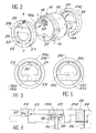
- the dosing pump shown is of the type described in patent FR-A-2,586,064. It therefore comprises a membrane 1 of pre-formed plastic material which is intended to serve as a suction and delivery device. The edges of this membrane are trapped between the body 2 of the pump and a cylinder head 3 attached to it and fixed by means of screws 4 or claws making it possible to assemble, in a single operation, the cover 13, the cylinder head 3 , the membrane 1, the body 2 and the casing of the control electromagnet. On one of its faces, the membrane 1 comprises a protector 5 on which is fixed an operating rod 6. This crosses the coil 7 of an electromagnet and it carries at the end a magnet 8 capable of being attracted to it. A return spring 9 is also provided to return the membrane 1 to its normal position.
- the opposite face of this membrane is arranged opposite a valve box constituted by a small cylindrical body 10.
- the latter is disposed in a housing 11 provided inside the cylinder head 3 and which opens in the direction of the membrane 1.
- the space 12 existing between this membrane and the corresponding face of the body 10 constitutes the pumping volume which is by definition extremely limited, since it must correspond to the expected dose of the liquid to be pumped.
- the body 10 is held in place by a cover 13 attached to the cylinder head 3 and which includes a pipe 14 for discharging the pumped product.
- the suction pipe 15 it is provided on the opposite side, inside the cylinder head 3, this pipe opening into the housing 11 of the valve box.
- the body 10 of the valve box has two respectively suction 16 and discharge 17 channels which communicate one with the suction duct 15 and the other with the discharge duct 14.
- the outlet of the suction channel 16 is located on the face of the body 10 which is placed opposite the membrane 1.
- the outlet of the discharge channel 17 it is located on the opposite face of the body 10.
- the corresponding face of this body 10 has a small cylindrical housing 18 inside which is disposed a rigid flat pad 19a or 19b, of preferably stainless steel which is suitable for use as a suction or discharge valve.
- an annular collar 20 intended to constitute the seat of the corresponding valve.
- the housing 18 of the suction valve 19a is open in the direction of the membrane 1.
- the housing 18 of the suction valve 19b is open in the direction of a free space communicating with the discharge line 14.
- each of these parts comprises first of all a ring 22 which is fitted around the corresponding body 10 and is capable of ensuring the sealing of mounting thereof in its housing.
- each part 21a and 21b comprises a support plate 23 in the form of a bar which is arranged against the corresponding valve 19a or 19b. This bar extends transversely inside the ring 22 and at its ends it is integral with a hoop 24 which is attached to the ring 22 by two elastic tabs 25.
- the parts 21a and 21b are molded from a synthetic resin chosen accordingly.
- the whole formed by the bar 23, the arch 24 and the tongues 25 constitutes a deformable part which extends in a plane perpendicular to the axis of the ring 22 and the external face of which is normally in the same plane as the external face of this ring.
- the body 10 of the valve box On its periphery, the body 10 of the valve box has an annular shoulder 26 which is intended to limit the interlocking of the rings 22 of the two parts 21a and 21b.
- annular shoulder 26 On its periphery, the body 10 of the valve box has an annular shoulder 26 which is intended to limit the interlocking of the rings 22 of the two parts 21a and 21b.
- this clearance J As illustrated in FIG. 4. The existence of this clearance will allow a constraint of the deformable part of each part 21a and 21b when the assembly is tightened inside the housing 11, as explained in more detail below.
- each part 21a and 21b is mounted in place, the deformable part of the latter already undergoes an elastic deformation stress, which is due to the presence of a pin 27 projecting from each of the faces of the body 10.
- This pin is located on the side opposite to the support bar 23, opposite the corresponding end of the arch 24. This therefore causes the lifting of this end as shown in Figure 4 so that the bar 23 is applied with a certain pressure against the corresponding valve 19a or 19b.
- each of the parts 21a and 21b is able to constitute a return spring for the corresponding valve.
- the cover 13 is put in place and tightened by means of the screws 4. This causes the rings 22 of the two parts 21a and 21b to be compressed, so that these seal the assembly. During this compression of the rings 22, the outer shell 28 plays the role of a hooping member allowing these rings to fully play their role.
- the back and forth movements of the diaphragm 1 successively cause the valve 19a to be raised in the open position for suction of a dose of the liquid to be pumped, then the valve 19b to be lifted to the delivery of this same dose, the valve 19a then being pushed back into the closed position.
- the support plate 23 of each piece 21a or 21b ensures the return of the corresponding valve in its normal closed position after it has been moved away from it. Consequently, these two parts play both the role of a seal and a spring for each of the valves. Consequently, each of these parts replaces several of the parts provided in current dosing pumps of the same kind. This results in a great simplification and a reduction in the cost price.
- the assembly operations are also greatly simplified since the cylindrical body 10 can be put in place with all the parts associated with it.
- the risks of incompatibility of the dosing pump with certain liquids used in the chemical industry are reduced.
- the pump body, the cylinder head, the cover and the valve box 10 can be made by molding in the same synthetic resin, while the membrane 1 and the parts 21a and 21b can be molded from another synthetic resin having the desired qualities of elasticity and which is chosen according to the environment of use, the pellets 19a and 19b forming valves being for their part made of steel stainless.
- the metering pump according to the invention is not limited to the single embodiment described above for information only.
- the lifting pins 27 could possibly be eliminated, the initial reforming stress of the deformable part of the parts 21a and 21b then being ensured only by taking up the clearance J indicated in FIG. 4. But conversely, it would be possible possibly to remove this game while maintaining the lifting pins 27.
- the surrounding ferrule 28 can be eliminated, the rings 22 of the two parts 21a and 21b then applying directly against the internal wall of the corresponding housing 11.
- FIG. 5 represents an alternative embodiment in which the transverse bar 23c of support is carried by an arch 24c similar to the arch 24 of Figure 3, but which is connected to the outer ring 22c by two tongues 25c arranged differently from the tongues 25 and also working in a different way. Indeed, these tabs are arranged on either side of this hoop and near the bar 23c. In such a case, these bars are then able to work in torsion to ensure the application of the bar 23c against the corresponding valve 19a or 19b.
- the parts 21a and 21b forming both a seal and a return spring.
Landscapes
- Engineering & Computer Science (AREA)
- Mechanical Engineering (AREA)
- General Engineering & Computer Science (AREA)
- Reciprocating Pumps (AREA)
- Details Of Reciprocating Pumps (AREA)
Description
La présente invention est relative aux pompes doseuses destinées à l'industrie chimique pour la fourniture de très faible débit d'un produit liquide, prélevé dans une réserve et refoulé vers un appareil d'utilisation.The present invention relates to metering pumps intended for the chemical industry for the supply of a very low flow rate of a liquid product, taken from a reserve and discharged towards a device for use.
Plus précisément l'invention concerne les pompes doseuses du type de celle décrite dans le brevet FR-A-2.586.064. Dans cette pompe, l'organe d'aspiration et refoulement consiste en une membrane animée d'un mouvement de va et vient en regard d'une boite à clapets constituée par un corps cylindrique rapporté dans un logement correspondant et qui comporte deux canaux, respectivement d'aspiration et de refoulement du liquide à pomper. Chaque clapet consiste en une pastille mobile disposée dans un logement prévu à la sortie du canal correspondant, donc ouvert l'un vers le volume de pompage et l'autre vers la conduite de refoulement.More specifically, the invention relates to metering pumps of the type described in patent FR-A-2,586,064. In this pump, the suction and discharge member consists of a membrane driven in a back and forth movement opposite a valve box constituted by a cylindrical body added in a corresponding housing and which has two channels, respectively suction and delivery of the liquid to be pumped. Each valve consists of a movable pellet disposed in a housing provided at the outlet of the corresponding channel, therefore open, one towards the pumping volume and the other towards the delivery pipe.
Deux pièces en matière moulée sont prévues de part et d'autre du corps de la boîte à clapets.Two pieces of molded material are provided on either side of the body of the valve box.
Chacun de ces clapets est monté dans son logement avec interposition d'un joint annulaire, cependant qu'une rondelle élastique percée de trous de communication est disposée contre sa face opposée, le rappel de ce clapet dans sa position normale de fermeture étant assuré par un tampon en matériau alvéolaire élastique, à porosité ouverte, servant de ressort. Pour l'un des deux clapets, ce tampon est interposé entre la rondelle élastique percée de trous et la membrane mobile servant d'organe d'aspiration et de refoulement. En ce qui concerne l'autre clapet, le tampon élastique d'appui est interposé entre la rondelle élastique correspondante et la paroi du couvercle du corps de pompe.Each of these valves is mounted in its housing with the interposition of an annular seal, while an elastic washer pierced with communication holes is disposed against its opposite face, the return of this valve in its normal closed position being ensured by a buffer of elastic cellular material, with open porosity, serving as a spring. For one of the two valves, this buffer is interposed between the elastic washer pierced with holes and the movable membrane serving as a suction and discharge member. As regards the other valve, the elastic support pad is interposed between the corresponding elastic washer and the wall of the pump body cover.
Les mouvements de va et vient de la membrane d'aspiration et de refoulement sont commandés par un système mécanique ou électromagnétique. L'agencement ainsi prévu permet d'assurer, successivement, l'aspiration d'un volume donné de liquide à travers le clapet d'aspiration, en fin de course la fermeture de ce clapet puis, le mouvement de la membrane s'inversant, l'ouverture du clapet de refoulement et l'expulsion du volume de liquide préalablement aspiré.The back and forth movements of the suction and discharge membrane are controlled by a mechanical or electromagnetic system. The arrangement thus provided makes it possible to ensure, successively, the suction of a given volume of liquid through the suction valve, at the end of the race, the closure of this valve then, the movement of the membrane reversing, the opening of the discharge valve and the expulsion of the volume of liquid previously aspirated.
Le fonctionnement de cette pompe donne entière satisfaction. Toutefois, celle-ci présente pour inconvénient de comporter un grand nombre d'organes différents à l'endroit de la boîte à clapets. Or ceci grève le prix de revient, non seulement à cause du prix de ces différentes pièces, mais également en raison de la complication qui en résulte pour les opérations de montage. Par ailleurs, comme ces pièces sont réalisées en des matériaux de natures différentes, ceci augmente les risques d'incompatibilité de la pompe correspondante avec différents produits liquides utilisés dans l'industrie chimique.The operation of this pump is entirely satisfactory. However, this has the drawback of having a large number of different members at the location of the valve box. However this strikes the cost price, not only because of the price of these different parts, but also because of the complication which results for the assembly operations. Furthermore, as these parts are made of materials of different natures, this increases the risks of incompatibility of the corresponding pump with different liquid products used in the chemical industry.
C'est pourquoi la présente invention a pour objet une pompe du même type général mais qui est conçue de façon à éliminer les inconvénients mentionnés ci-dessus et à apporter un certain nombre de perfectionnements.This is why the present invention relates to a pump of the same general type but which is designed so as to eliminate the drawbacks mentioned above and to provide a certain number of improvements.
L'objet de la présente invention est une pompe doseuse dont l'organe d'aspiration et de refoulement consiste en une membrane animée d'un mouvement de va et vient en regard d'une boîte à clapets constituée par un corps cylindrique rapporté dans un logement correspondant et qui comporte deux canaux, respectivement d'aspiration et de refoulement, du liquide à pomper, chaque clapet consistant en une pastille mobile disposée dans un logement prévu à la sortie du canal correspondant, donc ouvert l'un vers le volume de pompage et l'autre vers la conduite de refoulement, deux pièces en matière moulée étant prévues de part et d'autre du corps de la boîte à clapets, caractérisée en ce que les pièces en matière moulée comprennent chacune d'une part une bague emboîtée sur le bord correspondant de ce corps et apte à assurer l'étanchéité de montage de celui-ci dans son logement, et d'autre part au moins une languette élastique solidaire de ladite bague et portant une plaquette d'appui disposée contre la pastille du clapet correspondant afin de servir de ressort apte à assurer le rappel de cette pastille en position normale de fermeture après son soulèvement en position d'ouverture.The object of the present invention is a metering pump, the suction and discharge member of which consists of a membrane driven in a reciprocating movement opposite a valve box constituted by a cylindrical body attached in a corresponding housing and which comprises two channels, respectively of suction and discharge, of the liquid to be pumped, each valve consisting of a movable pellet disposed in a housing provided at the outlet of the corresponding channel, therefore open one towards the pumping volume and the other towards the discharge pipe, two pieces of molded material being provided on either side of the body of the valve box, characterized in that the pieces of molded material each comprise on the one hand a ring fitted on the corresponding edge of this body and capable of ensuring the sealing of mounting thereof in its housing, and on the other hand at least one elastic tongue integral with said ring and carrying a pla support quilt arranged against the pad of the corresponding valve in order to serve spring capable of ensuring the return of this pellet in the normal closed position after its lifting in the open position.
Selon d'autres particularités de l'invention :
- dans chacune des pièces formant à la fois ressort et joint d'étanchéité, la plaquette d'appui sur une pastille formant clapet consiste en une barrette plate dont les extrémités sont solidaires d'un arceau attaché à la bague d'étanchéité par deux languettes élastiques situées du côté opposé à la barrette d'appui et disposées de part et d'autre d'une ligne perpendiculaire à celle-ci, ces languettes étant aptes à se déformer élastiquement par flexion.
- dans chacune des pièces formant à la fois ressort et joint d'étanchéité, la plaquette d'appui sur une pastille formant clapet consiste en une barrette plate dont les extrémités sont solidaires d'un arceau attaché à la bague d'étanchéité par deux languettes élastiques, disposées de part et d'autre de cet arceau, et qui sont aptes à se déformer élastiquement en torsion.
- chaque face du corps de la boîte à clapet comporte un picot de soulèvement disposé en regard de l'arceau portant la barrette d'appui, ce picot étant situé du côté opposé à celui de cette barrette pour exercer sur l'ensemble déformable correspondant une contrainte tendant à appliquer la barrette d'appui contre la pastille respective formant clapet.
- sur son pourtour, le corps de la boîte à clapets comporte un épaulement déterminant la valeur de l'emboîtement de la bague d'étanchéitè de chacune des deux pièces rapportées de part et d'autre, et cette valeur est telle qu'après serrage en place de l'ensemble, la partie déformable formée par la barrette d'appui, l'arceau et les languettes d'attache subit une contrainte tendant à appliquer la barrette d'appui contre la pastille respective formant clapet.
- le corps cylindrique de la boîte à clapets est disposé à l'intérieur d'une virole de frettage qui se trouve ainsi interposée entre ce corps et la paroi interne de son logement.
- in each of the parts forming both a spring and a seal, the support plate on a flap forming a valve consists of a flat bar, the ends of which are secured to a hoop attached to the seal ring by two elastic tabs located on the side opposite to the support bar and arranged on either side of a line perpendicular thereto, these tongues being able to deform elastically by bending.
- in each of the parts forming both a spring and a seal, the support plate on a flap forming a valve consists of a flat bar, the ends of which are secured to a hoop attached to the seal ring by two elastic tabs , arranged on either side of this arch, and which are capable of elastically deforming in torsion.
- each face of the body of the valve box has a lifting pin arranged opposite the hoop carrying the support bar, this pin being located on the side opposite to that of this bar to exert stress on the corresponding deformable assembly tending to apply the support bar against the respective disc forming a valve.
- on its periphery, the body of the valve box has a shoulder determining the value of the fitting of the sealing ring of each of the two attached parts on either side, and this value is such that after tightening in place of the assembly, the deformable part formed by the support bar, the hoop and the fastening tabs is subjected to a stress tending to apply the support bar against the respective pad forming a valve.
- the cylindrical body of the valve box is arranged inside a hoop which is is thus interposed between this body and the internal wall of its housing.
Dans ces conditions, si l'on fait abstraction des deux clapets, le nombre de pièces associées à la boîte à clapets se trouve réduit aux deux pièces prévues de part et d'autre de celle-ci et dont chacune est apte à constituer à la fois un joint d'étanchéité et le ressort de rappel du clapet correspondant. Or ces pièces, qui sont identiques entre elles, sont fabriquées de façon économique par moulage en une résine synthétique convenablement choisie pour que la languette portant la plaquette d'appui présente une élasticité satisfaisante.Under these conditions, if we disregard the two valves, the number of parts associated with the box valves is reduced to the two parts provided on either side thereof and each of which is capable of constituting both a seal and the return spring of the corresponding valve. However, these parts, which are identical to each other, are produced economically by molding in a synthetic resin suitably chosen so that the tongue carrying the support plate has satisfactory elasticity.
D'autre part ces deux pièces peuvent être emboîtées à l'avance sur la boite à clapets de part et d'autre de celle-ci, ce qui facilite considérablement les opérations de montage de l'ensemble à l'intérieur du logement prévu.On the other hand these two parts can be fitted in advance on the valve box on either side thereof, which considerably facilitates the assembly operations of the assembly inside the housing provided.
Cependant d'autres particularités et avantages de la pompe doseuse selon l'invention apparaîtront au cours de la description d'un exemple de la réalisation de celle-ci. Cette description est donnée en référence aux dessins annexés à simple titre indicatif et sur lesquels :
- . La figure 1 est une vue en coupe longitudinale d'une pompe doseuse selon l'invention
- . La figure 2 est une vue en perspective de la boite à clapets et des deux pièces rapportées de part et d'autre de celle-ci, ces pièces étant représentées avant montage.
- . La figure 3 est une vue en plan de dessus de l'une de ces deux pièces
- . La figure 4 est une vue schématique en coupe longitudinale illustrant le mode de montage et de fonctionnement de d'une des pièces rapportée contre la boite à clapets
- . La figure 5 est une vue similaire de la figure 3 mais qui représente une variante de réalisation.
- . Figure 1 is a longitudinal sectional view of a metering pump according to the invention
- . Figure 2 is a perspective view of the valve box and the two attached parts on either side thereof, these parts being shown before assembly.
- . Figure 3 is a top plan view of one of these two parts
- . Figure 4 is a schematic view in longitudinal section illustrating the mounting and operating mode of one of the parts attached against the valve box
- . Figure 5 is a similar view of Figure 3 but which shows an alternative embodiment.
La pompe doseuse représentée est du type de celle décrite dans le brevet FR-A-2.586.064. Elle comporte donc une membrane 1 en matériau plastique pré-formé qui est destinée à servir d'organe d'aspiration et de refoulement. Les bords de cette membrane sont emprisonnés entre le corps 2 de la pompe et une culasse 3 rapportée sur celui-ci et fixée au moyen de vis 4 ou de griffes permettant d'assembler, en une seule opération, le couvercle 13, la culasse 3, la membrane 1, le corps 2 et la carcasse de l'électro-aimant de commande. Sur l'une de ses faces, la membrane 1 comporte une protéburance 5 sur laquelle est fixée une tige de manoeuvre 6. Celle-ci traverse la bobine 7 d'un électro-aimant et elle porte en bout un aimant 8 susceptible d'être attiré par celui-ci. Un ressort de rappel 9 est par ailleurs prévu pour ramener la membrane 1 dans sa position normale.The dosing pump shown is of the type described in patent FR-A-2,586,064. It therefore comprises a
La face opposée de cette membrane est disposée en regard d'une boite à clapets constituée par un petit corps cylindrique 10. Celui-ci est disposé dans un logement 11 prévu à l'intérieur de la culasse 3 et qui s'ouvre en direction de la membrane 1. L'espace 12 existant entre cette membrane et la face correspondante du corps 10 constitue le volume de pompage qui est par définition extrêmement restreint, puisqu'il doit correspondre à la dose prévue du liquide à pomper. Le maintien en place du corps 10 est assuré par un couvercle 13 rapporté sur la culasse 3 et qui comporte un conduit 14 de refoulement du produit pompé. Quant à la conduite 15 d'aspiration, elle est prévue du côté opposé, à l'intérieur de la culasse 3, cette conduite débouchant dans le logement 11 de la boite à clapets.The opposite face of this membrane is arranged opposite a valve box constituted by a small
Pour sa part, le corps 10 de la boite à clapets comporte deux canaux respectivement d'aspiration 16 et de refoulement 17 qui communiquent l'un avec le conduit d'aspiration 15 et l'autre avec le conduit de refoulement 14. La sortie du canal d'aspiration 16 est située sur la face du corps 10 qui est placée en regard de la membrane 1. Quant à la sortie du canal 17 de refoulement, elle est située sur la face opposée du corps 10. A la sortie de chacun de ces canaux 16 et 17, la face correspondante de ce corps 10 comporte un petit logement cylindrique 18 à l'intérieur duquel est disposée une pastille plate rigide 19a ou 19b, de préférence en acier inoxydable qui est apte à servir de clapet d'aspiration ou de refoulement. Dans le fond de chaque logement 18, il est prévu un collet annulaire 20 destiné à constituer le siège du clapet correspondant.For its part, the
Compte tenu de l'agencement prévu, le logement 18 du clapet d'aspiration 19a est ouvert en direction de la membrane 1. Par contre le logement 18 du clapet 19 b d'aspiration est ouvert en direction d'un espace libre communiquant avec la conduite de refoulement 14.Given the arrangement provided, the
De part et d'autre du corps 10 de la boite à clapets, il est prévu deux pièces identiques en matière moulée qui sont désignées respectivement par les références générales 21a et 21b. Chacune de ces pièces comporte en premier lieu une bague 22 qui est emboîtée autour du corps correspondant 10 et est apte à assurer l'étanchéité de montage de celui-ci dans son logement. En second lieu, chaque pièce 21a et 21b comprend une plaquette d'appui 23 en forme de barrette qui est disposée contre le clapet correspondant 19a ou 19b. Cette barrette s'étend transversalement à l'intérieur de la bague 22 et à ses extrêmités elle est solidaire d'un arceau 24 qui est attaché à la bague 22 par deux languettes élastiques 25. Ces deux languettes sont situées du côté opposé à la barrette d'appui 23 et elles sont disposées de part et d'autre d'une ligne diamétrale XY qui s'étend à angle droit par rapport à cette barrette. Ces deux languettes d'attache sont susceptibles de se déformer élastiquement par flexion. A cet effet, les pièces 21a et 21b sont moulées en une résine synthétique choisie en conséquence. Dans chacune de ces deux pièces, l'ensemble formé par la barrette 23, l'arceau 24 et les languettes 25 constitue une partie déformable qui s'étend dans un plan perpendiculaire à l'axe de la bague 22 et dont la face externe est normalement dans le même plan que la face externe de cette bague.On either side of the
Sur son pourtour, le corps 10 de la boite à clapets comporte un épaulement annulaire 26 qui est destiné à limiter l'emboîtement des bagues 22 des deux pièces 21a et 21b. Cependant, lorsque chacune de ces pièces est emboîtée sur le corps 10 avant que l'ensemble soit placé dans son logement, il existe un jeu J, comme illustré à la figure 4. L'existence de ce jeu permettra de réaliser une contrainte de la partie déformable de chaque pièce 21a et 21b lorsque l'ensemble sera serré à l'intérieur du logement 11, comme exposé plus en détails par la suite.On its periphery, the
Cependant dès le montage en place de chaque pièce 21a et 21b, la partie déformable de celle-ci subit déjà une contrainte de déformation élastique, qui est dûe à la présence d'un picot 27 prévu en saillie sur chacune des faces du corps 10. Ce picot est situé du côté opposé à la barrette d'appui 23, en regard de l'extrêmité correspondante de l'arceau 24. Ceci provoque donc le soulèvement de cette extrêmité comme représenté sur la figure 4 de sorte que la barrette 23 se trouve appliquée avec une certaine pression contre le clapet correspondant 19a ou 19b. Ainsi chacune des pièces 21a et 21b est apte à constituer un ressort de rappel pour le clapet correspondant.However, as soon as each
Ces deux pièces 21a et 21b sont emboîtées sur le corps 10 de la boite à clapets avant montage de celle-ci dans son logement. Cependant, une virole 28 est également disposée autour de l'ensemble avant mise en place de celui-ci dans son logement. Lorsque toutes ces pièces sont emboîtées les une sur les autres, elles constituent un ensemble d'un seul tenant à l'intérieur duquel les clapets 19a et 19b sont maintenus en place par les barrettes d'appui 23. Cet ensemble peut donc être stocké sous cette forme pour être ensuite mis en place à l'intérieur du logement 11. Ceci facilite donc considérablement les opérations de montage puisque toutes les pièces associées à la boite à clapets se trouvent mises en place en même temps que celle-ci.These two
Après cette opération de montage, le couvercle 13 est mis en place et serré au moyen des vis 4. Ceci provoque la compression des bagues 22 des deux pièces 21a et 21b, de sorte que celles-ci assurent l'étanchéité du montage. Lors de cette compression des bagues 22, la virole externe 28 joue le rôle d'un organe de frettage permettant à ces bagues de jouer pleinement leur rôle.After this mounting operation, the
Il faut également observer que, lors du serrage de la boite à clapets, les bagues 22 des deux pièces 21a et 21b se trouvent repoussées contre l'épaulement 26 du corps 10. Ceci réalise une contrainte de déformation élastique sur la partie déformable de chaque pièce 21a et 21b en renforçant par là même la pression élastique de chaque barrette d'appui 23 contre le clapet correspondant 19a ou 19b.It should also be observed that, when the valve box is tightened, the
Lors du fonctionnement de la présente pompe, les mouvements de va et vient de la membrane 1 provoquent successivement le soulèvement du clapet 19a en position d'ouverture pour l'aspiration d'une dose du liquide à pomper, puis le soulèvement du clapet 19b pour le refoulement de cette même dose, le clapet 19a étant alors repoussé en position de fermeture. Dans chaque cas la plaquette d'appui 23 de chaque pièce 21a ou 21b assure le rappel du clapet correspondant dans sa position normale de fermeture après qu'il ait été écarté de celle-ci. En conséquence, ces deux pièces jouent à la fois le rôle d'un joint d'étanchéité et d'un ressort pour chacun des clapets. En conséquence, chacune de ces pièces remplace plusieurs des pièces prévues dans les pompes doseuses actuelles du même genre. Il en résulte une grande simplification et une réduction du prix de revient. Les opérations de montage se trouvent également grandement simplifiées puisque le corps cylindrique 10 peut être mis en place avec toutes les pièces qui lui sont associées. Par ailleurs les risques d'incompatibilité de la pompe doseuse avec certains liquides utilisés dans l'industrie chimique se trouvent réduits. En effet, grâce à l'agencement prévu, il n'existe que trois matériaux de nature différente puisque le corps de pompe, la culasse, le couvercle et la boîte à clapets 10 peuvent être réalisés par moulage en une même résine synthétique, alors que la membrane 1 et les pièces 21a et 21 b peuvent être moulées en une autre résine synthétique présentant les qualités voulues d'élasticité et qui est choisie en fonction du milieu d'utilisation, les pastilles 19a et 19b formant clapets étant pour leur part en acier inoxydable.During the operation of the present pump, the back and forth movements of the
Cependant la pompe doseuse selon l'invention n'est pas limitée au seul exemple de réalisation décrit ci-dessus à simple titre indicatif. Ainsi, les picots 27 de soulèvement pourraient éventuellement être supprimés, la contrainte de réformation initiale de la partie déformable des pièces 21a et 21b étant alors assurée uniquement par le rattrapage du jeu J indiqué à la figure 4. Mais inversement il serait éventuellement possible de supprimer ce jeu en maintenant alors les picots 27 de soulèvement. Par ailleurs la virole 28 d'entourage peut être supprimée, les bagues 22 des deux pièces 21a et 21b s'appliquant alors directement contre la paroi interne du logement correspondant 11.However, the metering pump according to the invention is not limited to the single embodiment described above for information only. Thus, the lifting pins 27 could possibly be eliminated, the initial reforming stress of the deformable part of the
Quant aux pièces 21a et 21b elles pourraient être réalisées sous une forme différente. Ainsi la figure 5 représente une variante de réalisation dans laquelle la barrette transversale 23c d'appui est portée par un arceau 24c similaire à l'arceau 24 de la figure 3, mais qui est relié à la bague externe 22c par deux languettes 25c disposées de façon différente des languettes 25 et travaillant également de manière différente. En effet, ces languettes sont disposées de part et d'autre de cet arceau et à proximité de la barrette 23c. Dans un tel cas ces barrettes sont alors aptes à travailler en torsion pour assurer l'application de la barrette 23c contre le clapet correspondant 19a ou 19b. Mais de nombreuses autres formes de réalisation pourraient être envisagées pour les pièces 21a et 21b formant à la fois joint d'étanchéité et ressort de rappel.As for
Claims (6)
- A dosing pump wherein the suction and discharge member consists of a membrane (1) driven into a réciprocating motion in registry with a valve chest constituted by a cylindrical body (10) inserted within a corresponding housing (11) and which comprises two ducts (16, 17) respectively a suction duct (16) and a discharge duct (17) for the liquid to be pumped, each valve (19a or 19b) consisting of a movable disc disposed in a recess (18) provided at the outlet of the corresponding duct (16 or 17) and being therefore open, one of them opening towards the pumping volume (12) and the other one opening towards the discharge duct, two pieces (21a and 21b) made of moulded material being provided on either side of the body (10) of the valve chest,
characterized in that said pieces (21a and 21b) made of moulded material each comprise on the one hand a ring (22) fitted over the corresponding edge of said body and adapted for ensuring a fluid-tight fit thereof in its housing (11), and on the other hand at least one resilient tongue (25) bound up with said ring (22) and carrying a pressing plate (23) disposed against the disc (19a, 19b) of the corresponding valve in order to serve as a spring adapted for returning said disc into its normal closing position after it has been lifted into its opening position. - A dosing pump according to Claim 1, characterized in that, in each of the pieces (21a, 21b) forming both a spring and a fluid-tight gasket, the plate pressing against a disc (19a, 19b) forming a valve member consists of a flat bar (23), the ends of which are bound up with a bow-shaped member (24) attached to the sealing ring (22) by two resilient tongues (25) located on the side opposite the pressing bar (23) and disposed on either side of a line perpendicular thereto, said tongues being adapted for being resiliently deformed through flexion.
- A dosing pump according to Claim 1, characterized in that, in each one of the pieces forming both a spring and a sealing gasket, the plate pressing against a disc (19a, 19b) forming a valve member consists of a flat bar (23c) the ends of which are bound up with a bow-shaped member (24c) attached to the sealing ring (22c) by means of two resilient tongues (25c) disposed on either side of said bow-shaped member and adapted for being resiliently deformed through flexion.
- A dosing pump according to one of Claims 2 and 3, characterized in that each face of the body (10) of the valve chest carries a lifting stud (27) disposed in registry with the bow-shaped member (24) carrying the pressure bar (23), said stud being located on the side opposite the side of said bar for exerting upon the corresponding deformable assembly a stress which tends to press the pressure bar (23) against the respective disc (19a, 19b) forming a valve member.
- A dosing pump according to one of Claims 1 - 4, characterized in that the valve chest body (10) carries on its periphery a shoulder (26) determining the extent of the depth of insertion of the sealing ring (22) of each one of the two pieces (21a, 21b) added on respectively to both sides of said body, this extent being such that after the assembly has been fitted together and tightened, the deformable portion formed by the pressure bar (23), the bow-shaped member (24) and the fastening tongues (25) is subjected to a stress tending to press the pressure bar (23) against the respective disc (19a, 19b) forming a valve member.
- A dosing pump according to one of the preceding Claims, characterized in that the cylindrical body (10) of the valve chest is disposed inside a hooping sleeve (28) which thus finds itself interposed between said body and the inner wall of its housing (11).
Applications Claiming Priority (2)
| Application Number | Priority Date | Filing Date | Title |
|---|---|---|---|
| FR9005894A FR2661955B1 (en) | 1990-05-11 | 1990-05-11 | METERING PUMP. |
| FR9005894 | 1990-05-11 |
Publications (2)
| Publication Number | Publication Date |
|---|---|
| EP0456540A1 EP0456540A1 (en) | 1991-11-13 |
| EP0456540B1 true EP0456540B1 (en) | 1993-06-23 |
Family
ID=9396511
Family Applications (1)
| Application Number | Title | Priority Date | Filing Date |
|---|---|---|---|
| EP91401042A Expired - Lifetime EP0456540B1 (en) | 1990-05-11 | 1991-04-19 | Dosingpump |
Country Status (3)
| Country | Link |
|---|---|
| EP (1) | EP0456540B1 (en) |
| DE (1) | DE69100138T2 (en) |
| FR (1) | FR2661955B1 (en) |
Family Cites Families (5)
| Publication number | Priority date | Publication date | Assignee | Title |
|---|---|---|---|---|
| US3034450A (en) * | 1956-05-09 | 1962-05-15 | Tokheim Corp | Hand operated diaphragm pump |
| GB1013298A (en) * | 1962-10-12 | 1965-12-15 | Vyzk Ustav Prislusenstvi Motor | Electromagnetic fuel feeding pump |
| US3461808A (en) * | 1967-07-03 | 1969-08-19 | Wood John Co | Diaphragm hand pumps |
| DE2855541C2 (en) * | 1978-12-22 | 1982-05-19 | Zahnradfabrik Friedrichshafen Ag, 7990 Friedrichshafen | Pressure valve for a piston pump |
| FR2586064B1 (en) * | 1985-08-06 | 1987-10-23 | Alpha Plastiques | METERING PUMP |
-
1990
- 1990-05-11 FR FR9005894A patent/FR2661955B1/en not_active Expired - Fee Related
-
1991
- 1991-04-19 DE DE91401042T patent/DE69100138T2/en not_active Expired - Fee Related
- 1991-04-19 EP EP91401042A patent/EP0456540B1/en not_active Expired - Lifetime
Also Published As
| Publication number | Publication date |
|---|---|
| FR2661955A1 (en) | 1991-11-15 |
| FR2661955B1 (en) | 1992-07-24 |
| EP0456540A1 (en) | 1991-11-13 |
| DE69100138T2 (en) | 1993-09-30 |
| DE69100138D1 (en) | 1993-07-29 |
Similar Documents
| Publication | Publication Date | Title |
|---|---|---|
| EP2723504B1 (en) | System for closing a device for the low-pressure dispensing of a pasty liquid material | |
| EP0705143B1 (en) | Spray nozzle and vaporizer provided with such nozzle | |
| EP1462180A2 (en) | Multiple-dose device for dispensing a fluid product | |
| EP2136931A1 (en) | Device for dispensing a liquid to pasty product with a dosing pump | |
| FR2489791A1 (en) | DISPENSING DEVICE FOR PASTY OR VISCOUS AGENTS | |
| FR2813283A1 (en) | INTEGRATED PUMP DISPENSER | |
| FR3048192A1 (en) | PUMP FOR RECEPTACLE, IN PARTICULAR A BOTTLE OF COSMETIC PRODUCT, AND DISPENSING DEVICE COMPRISING SUCH A PUMP | |
| EP1670700A2 (en) | Fluid product dispensing head | |
| EP3592470B1 (en) | Device for dispensing a product with improved triggering | |
| EP1871536A2 (en) | Dispensing head | |
| EP3206968B1 (en) | Device for dispensing a cosmetic product in aerosol form, associated assembly and method | |
| EP0456540B1 (en) | Dosingpump | |
| EP2618940A1 (en) | Device for dispensing a liquid and method of manufacturing such a device | |
| EP1146165B1 (en) | Water filling opening for an iron | |
| EP1631510B1 (en) | Distribution element for a liquid product | |
| FR2810302A1 (en) | Dynamic air replenishing device for liquid product dispenser comprises flat ring forming joint sealing supported beneath pump body truncated shoulder | |
| EP3393298B1 (en) | Cosmetic pot comprising a system for pressurising a product supply container | |
| BE1008193A3 (en) | Volumetric dosing powder products including. | |
| EP0805719B1 (en) | Pump with a single-piece inlet valve and assembly for moulding said valve | |
| FR3061156A1 (en) | DIFFUSER ASSEMBLY FOR AEROSOL | |
| WO2003086646A1 (en) | Distribution pump for a fluid product | |
| FR2729925A1 (en) | Membrane measuring stopper for flexible bottle | |
| FR3040270A1 (en) | COSMETIC PRODUCT DELIVERY PUMP AND DISPENSING DEVICE COMPRISING SUCH A PUMP | |
| FR2997873A1 (en) | Distribution device for use on rigid container to distribute e.g. cosmetic cream, has valve complementary to non-deformable lower part of orifice, so that valve ensures sealing when valve is static or raised during expulsion of product | |
| FR3070280A1 (en) | DEVICE FOR PACKAGING AND DISPENSING A PRODUCT, IN PARTICULAR A PHARMACEUTICAL OR COSMETIC PRODUCT |
Legal Events
| Date | Code | Title | Description |
|---|---|---|---|
| PUAI | Public reference made under article 153(3) epc to a published international application that has entered the european phase |
Free format text: ORIGINAL CODE: 0009012 |
|
| AK | Designated contracting states |
Kind code of ref document: A1 Designated state(s): DE GB IT |
|
| 17P | Request for examination filed |
Effective date: 19920208 |
|
| 17Q | First examination report despatched |
Effective date: 19920527 |
|
| ITF | It: translation for a ep patent filed | ||
| GRAA | (expected) grant |
Free format text: ORIGINAL CODE: 0009210 |
|
| AK | Designated contracting states |
Kind code of ref document: B1 Designated state(s): DE GB IT |
|
| PG25 | Lapsed in a contracting state [announced via postgrant information from national office to epo] |
Ref country code: GB Effective date: 19930623 |
|
| REF | Corresponds to: |
Ref document number: 69100138 Country of ref document: DE Date of ref document: 19930729 |
|
| GBV | Gb: ep patent (uk) treated as always having been void in accordance with gb section 77(7)/1977 [no translation filed] |
Effective date: 19930623 |
|
| PGFP | Annual fee paid to national office [announced via postgrant information from national office to epo] |
Ref country code: DE Payment date: 19940408 Year of fee payment: 4 |
|
| PLBE | No opposition filed within time limit |
Free format text: ORIGINAL CODE: 0009261 |
|
| STAA | Information on the status of an ep patent application or granted ep patent |
Free format text: STATUS: NO OPPOSITION FILED WITHIN TIME LIMIT |
|
| 26N | No opposition filed | ||
| PG25 | Lapsed in a contracting state [announced via postgrant information from national office to epo] |
Ref country code: DE Effective date: 19960103 |
|
| PG25 | Lapsed in a contracting state [announced via postgrant information from national office to epo] |
Ref country code: IT Free format text: LAPSE BECAUSE OF NON-PAYMENT OF DUE FEES;WARNING: LAPSES OF ITALIAN PATENTS WITH EFFECTIVE DATE BEFORE 2007 MAY HAVE OCCURRED AT ANY TIME BEFORE 2007. THE CORRECT EFFECTIVE DATE MAY BE DIFFERENT FROM THE ONE RECORDED. Effective date: 20050419 |