EP0456540B1 - Dosierpumpe - Google Patents
Dosierpumpe Download PDFInfo
- Publication number
- EP0456540B1 EP0456540B1 EP91401042A EP91401042A EP0456540B1 EP 0456540 B1 EP0456540 B1 EP 0456540B1 EP 91401042 A EP91401042 A EP 91401042A EP 91401042 A EP91401042 A EP 91401042A EP 0456540 B1 EP0456540 B1 EP 0456540B1
- Authority
- EP
- European Patent Office
- Prior art keywords
- valve
- disc
- bar
- forming
- dosing pump
- Prior art date
- Legal status (The legal status is an assumption and is not a legal conclusion. Google has not performed a legal analysis and makes no representation as to the accuracy of the status listed.)
- Expired - Lifetime
Links
- 239000012528 membrane Substances 0.000 claims description 17
- 210000002105 tongue Anatomy 0.000 claims description 11
- 239000000463 material Substances 0.000 claims description 9
- 239000007788 liquid Substances 0.000 claims description 8
- 238000007789 sealing Methods 0.000 claims description 7
- 238000005086 pumping Methods 0.000 claims description 4
- 230000037431 insertion Effects 0.000 claims 1
- 238000003780 insertion Methods 0.000 claims 1
- 208000031968 Cadaver Diseases 0.000 description 4
- 235000010603 pastilles Nutrition 0.000 description 4
- 239000008188 pellet Substances 0.000 description 4
- 229920003002 synthetic resin Polymers 0.000 description 4
- 239000000057 synthetic resin Substances 0.000 description 4
- 239000000126 substance Substances 0.000 description 3
- 238000005452 bending Methods 0.000 description 2
- 230000005489 elastic deformation Effects 0.000 description 2
- 239000012263 liquid product Substances 0.000 description 2
- 238000000465 moulding Methods 0.000 description 2
- 229940012982 picot Drugs 0.000 description 2
- 229910000831 Steel Inorganic materials 0.000 description 1
- 241001080024 Telles Species 0.000 description 1
- 240000008042 Zea mays Species 0.000 description 1
- 230000001413 cellular effect Effects 0.000 description 1
- 210000000078 claw Anatomy 0.000 description 1
- 238000004891 communication Methods 0.000 description 1
- 230000006835 compression Effects 0.000 description 1
- 238000007906 compression Methods 0.000 description 1
- 238000007599 discharging Methods 0.000 description 1
- 239000000047 product Substances 0.000 description 1
- 230000001012 protector Effects 0.000 description 1
- 238000002407 reforming Methods 0.000 description 1
- 229910001220 stainless steel Inorganic materials 0.000 description 1
- 239000010935 stainless steel Substances 0.000 description 1
- 239000010959 steel Substances 0.000 description 1
- 238000005728 strengthening Methods 0.000 description 1
Images

Classifications
-
- F—MECHANICAL ENGINEERING; LIGHTING; HEATING; WEAPONS; BLASTING
- F04—POSITIVE - DISPLACEMENT MACHINES FOR LIQUIDS; PUMPS FOR LIQUIDS OR ELASTIC FLUIDS
- F04B—POSITIVE-DISPLACEMENT MACHINES FOR LIQUIDS; PUMPS
- F04B53/00—Component parts, details or accessories not provided for in, or of interest apart from, groups F04B1/00 - F04B23/00 or F04B39/00 - F04B47/00
- F04B53/10—Valves; Arrangement of valves
- F04B53/109—Valves; Arrangement of valves inlet and outlet valve forming one unit
-
- F—MECHANICAL ENGINEERING; LIGHTING; HEATING; WEAPONS; BLASTING
- F04—POSITIVE - DISPLACEMENT MACHINES FOR LIQUIDS; PUMPS FOR LIQUIDS OR ELASTIC FLUIDS
- F04B—POSITIVE-DISPLACEMENT MACHINES FOR LIQUIDS; PUMPS
- F04B43/00—Machines, pumps, or pumping installations having flexible working members
- F04B43/02—Machines, pumps, or pumping installations having flexible working members having plate-like flexible members, e.g. diaphragms
- F04B43/04—Pumps having electric drive
-
- F—MECHANICAL ENGINEERING; LIGHTING; HEATING; WEAPONS; BLASTING
- F04—POSITIVE - DISPLACEMENT MACHINES FOR LIQUIDS; PUMPS FOR LIQUIDS OR ELASTIC FLUIDS
- F04B—POSITIVE-DISPLACEMENT MACHINES FOR LIQUIDS; PUMPS
- F04B53/00—Component parts, details or accessories not provided for in, or of interest apart from, groups F04B1/00 - F04B23/00 or F04B39/00 - F04B47/00
- F04B53/10—Valves; Arrangement of valves
- F04B53/1037—Flap valves
- F04B53/104—Flap valves the closure member being a rigid element oscillating around a fixed point
- F04B53/1042—Flap valves the closure member being a rigid element oscillating around a fixed point by means of a flexible connection
Definitions
- the present invention relates to metering pumps intended for the chemical industry for the supply of a very low flow rate of a liquid product, taken from a reserve and discharged towards a device for use.
- the invention relates to metering pumps of the type described in patent FR-A-2,586,064.
- the suction and discharge member consists of a membrane driven in a back and forth movement opposite a valve box constituted by a cylindrical body added in a corresponding housing and which has two channels, respectively suction and delivery of the liquid to be pumped.
- Each valve consists of a movable pellet disposed in a housing provided at the outlet of the corresponding channel, therefore open, one towards the pumping volume and the other towards the delivery pipe.
- Two pieces of molded material are provided on either side of the body of the valve box.
- Each of these valves is mounted in its housing with the interposition of an annular seal, while an elastic washer pierced with communication holes is disposed against its opposite face, the return of this valve in its normal closed position being ensured by a buffer of elastic cellular material, with open porosity, serving as a spring.
- this buffer is interposed between the elastic washer pierced with holes and the movable membrane serving as a suction and discharge member.
- the elastic support pad is interposed between the corresponding elastic washer and the wall of the pump body cover.
- the back and forth movements of the suction and discharge membrane are controlled by a mechanical or electromagnetic system.
- the arrangement thus provided makes it possible to ensure, successively, the suction of a given volume of liquid through the suction valve, at the end of the race, the closure of this valve then, the movement of the membrane reversing, the opening of the discharge valve and the expulsion of the volume of liquid previously aspirated.
- the present invention relates to a pump of the same general type but which is designed so as to eliminate the drawbacks mentioned above and to provide a certain number of improvements.
- the object of the present invention is a metering pump, the suction and discharge member of which consists of a membrane driven in a reciprocating movement opposite a valve box constituted by a cylindrical body attached in a corresponding housing and which comprises two channels, respectively of suction and discharge, of the liquid to be pumped, each valve consisting of a movable pellet disposed in a housing provided at the outlet of the corresponding channel, therefore open one towards the pumping volume and the other towards the discharge pipe, two pieces of molded material being provided on either side of the body of the valve box, characterized in that the pieces of molded material each comprise on the one hand a ring fitted on the corresponding edge of this body and capable of ensuring the sealing of mounting thereof in its housing, and on the other hand at least one elastic tongue integral with said ring and carrying a pla support quilt arranged against the pad of the corresponding valve in order to serve spring capable of ensuring the return of this pellet in the normal closed position after its lifting in the open position.
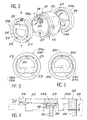
- the dosing pump shown is of the type described in patent FR-A-2,586,064. It therefore comprises a membrane 1 of pre-formed plastic material which is intended to serve as a suction and delivery device. The edges of this membrane are trapped between the body 2 of the pump and a cylinder head 3 attached to it and fixed by means of screws 4 or claws making it possible to assemble, in a single operation, the cover 13, the cylinder head 3 , the membrane 1, the body 2 and the casing of the control electromagnet. On one of its faces, the membrane 1 comprises a protector 5 on which is fixed an operating rod 6. This crosses the coil 7 of an electromagnet and it carries at the end a magnet 8 capable of being attracted to it. A return spring 9 is also provided to return the membrane 1 to its normal position.
- the opposite face of this membrane is arranged opposite a valve box constituted by a small cylindrical body 10.
- the latter is disposed in a housing 11 provided inside the cylinder head 3 and which opens in the direction of the membrane 1.
- the space 12 existing between this membrane and the corresponding face of the body 10 constitutes the pumping volume which is by definition extremely limited, since it must correspond to the expected dose of the liquid to be pumped.
- the body 10 is held in place by a cover 13 attached to the cylinder head 3 and which includes a pipe 14 for discharging the pumped product.
- the suction pipe 15 it is provided on the opposite side, inside the cylinder head 3, this pipe opening into the housing 11 of the valve box.
- the body 10 of the valve box has two respectively suction 16 and discharge 17 channels which communicate one with the suction duct 15 and the other with the discharge duct 14.
- the outlet of the suction channel 16 is located on the face of the body 10 which is placed opposite the membrane 1.
- the outlet of the discharge channel 17 it is located on the opposite face of the body 10.
- the corresponding face of this body 10 has a small cylindrical housing 18 inside which is disposed a rigid flat pad 19a or 19b, of preferably stainless steel which is suitable for use as a suction or discharge valve.
- an annular collar 20 intended to constitute the seat of the corresponding valve.
- the housing 18 of the suction valve 19a is open in the direction of the membrane 1.
- the housing 18 of the suction valve 19b is open in the direction of a free space communicating with the discharge line 14.
- each of these parts comprises first of all a ring 22 which is fitted around the corresponding body 10 and is capable of ensuring the sealing of mounting thereof in its housing.
- each part 21a and 21b comprises a support plate 23 in the form of a bar which is arranged against the corresponding valve 19a or 19b. This bar extends transversely inside the ring 22 and at its ends it is integral with a hoop 24 which is attached to the ring 22 by two elastic tabs 25.
- the parts 21a and 21b are molded from a synthetic resin chosen accordingly.
- the whole formed by the bar 23, the arch 24 and the tongues 25 constitutes a deformable part which extends in a plane perpendicular to the axis of the ring 22 and the external face of which is normally in the same plane as the external face of this ring.
- the body 10 of the valve box On its periphery, the body 10 of the valve box has an annular shoulder 26 which is intended to limit the interlocking of the rings 22 of the two parts 21a and 21b.
- annular shoulder 26 On its periphery, the body 10 of the valve box has an annular shoulder 26 which is intended to limit the interlocking of the rings 22 of the two parts 21a and 21b.
- this clearance J As illustrated in FIG. 4. The existence of this clearance will allow a constraint of the deformable part of each part 21a and 21b when the assembly is tightened inside the housing 11, as explained in more detail below.
- each part 21a and 21b is mounted in place, the deformable part of the latter already undergoes an elastic deformation stress, which is due to the presence of a pin 27 projecting from each of the faces of the body 10.
- This pin is located on the side opposite to the support bar 23, opposite the corresponding end of the arch 24. This therefore causes the lifting of this end as shown in Figure 4 so that the bar 23 is applied with a certain pressure against the corresponding valve 19a or 19b.
- each of the parts 21a and 21b is able to constitute a return spring for the corresponding valve.
- the cover 13 is put in place and tightened by means of the screws 4. This causes the rings 22 of the two parts 21a and 21b to be compressed, so that these seal the assembly. During this compression of the rings 22, the outer shell 28 plays the role of a hooping member allowing these rings to fully play their role.
- the back and forth movements of the diaphragm 1 successively cause the valve 19a to be raised in the open position for suction of a dose of the liquid to be pumped, then the valve 19b to be lifted to the delivery of this same dose, the valve 19a then being pushed back into the closed position.
- the support plate 23 of each piece 21a or 21b ensures the return of the corresponding valve in its normal closed position after it has been moved away from it. Consequently, these two parts play both the role of a seal and a spring for each of the valves. Consequently, each of these parts replaces several of the parts provided in current dosing pumps of the same kind. This results in a great simplification and a reduction in the cost price.
- the assembly operations are also greatly simplified since the cylindrical body 10 can be put in place with all the parts associated with it.
- the risks of incompatibility of the dosing pump with certain liquids used in the chemical industry are reduced.
- the pump body, the cylinder head, the cover and the valve box 10 can be made by molding in the same synthetic resin, while the membrane 1 and the parts 21a and 21b can be molded from another synthetic resin having the desired qualities of elasticity and which is chosen according to the environment of use, the pellets 19a and 19b forming valves being for their part made of steel stainless.
- the metering pump according to the invention is not limited to the single embodiment described above for information only.
- the lifting pins 27 could possibly be eliminated, the initial reforming stress of the deformable part of the parts 21a and 21b then being ensured only by taking up the clearance J indicated in FIG. 4. But conversely, it would be possible possibly to remove this game while maintaining the lifting pins 27.
- the surrounding ferrule 28 can be eliminated, the rings 22 of the two parts 21a and 21b then applying directly against the internal wall of the corresponding housing 11.
- FIG. 5 represents an alternative embodiment in which the transverse bar 23c of support is carried by an arch 24c similar to the arch 24 of Figure 3, but which is connected to the outer ring 22c by two tongues 25c arranged differently from the tongues 25 and also working in a different way. Indeed, these tabs are arranged on either side of this hoop and near the bar 23c. In such a case, these bars are then able to work in torsion to ensure the application of the bar 23c against the corresponding valve 19a or 19b.
- the parts 21a and 21b forming both a seal and a return spring.
Landscapes
- Engineering & Computer Science (AREA)
- Mechanical Engineering (AREA)
- General Engineering & Computer Science (AREA)
- Reciprocating Pumps (AREA)
- Details Of Reciprocating Pumps (AREA)
Claims (6)
- Dosierpumpe mit einem Ansaug- und Verdrängungsorgan, das aus einer Membran (1) besteht, die relativ zu einem Ventilgehäuse aus einem Zylindereinsatz (10) mit zwei Kanälen (16, 17) für die zu pumpende Flüssigkeit, - einem Ansaugkanal (16) und einem Verdrängungskanal (17) -, je einem Ventilkörper (19a oder 19b) aus einer beweglichen, in einem Ringraum (18) am Ende des betreffenden Kanals (16 oder 17) angeordneten Scheibe, wobei der eine Ventilkörper in Richtung auf das Pumpvolumen (12) und der andere in Richtung auf die Ausgangsleitung öffnet, und zwei zu beiden Seiten des Zylindereinsatzes (10) des Ventilgehäuses vorgesehenen Formkörpern (21a, 21b) hin- und hergehend angetrieben ist, dadurch gekennzeichnet, daß die Formkörper (21a, 21b) jeweils einerseits einen Ring (22), der randseitig an dem Zylindereinsatz aufgenommen und zur Abdichtung bei seiner Montage in einer Ausnehmung (11) ausgebildet ist, und andererseits mindestens einen elastischen, mit dem Ring (22) verbundenen und ein Anlagestück (23) tragenden Steg (25) aufweisen, wobei das Anlagestück (23) relativ zu dem betreffenden Ventilkörper (19a, 19b) angeordnet ist und dabei zur federnden Anlage des Ventilkörpers in der normalen Schließstellung nach seinem Anheben in die Öffnungsstellung dient.
- Dosierpumpe nach Anspruch 1, dadurch gekennzeichnet, daß an jedem gleichzeitig ein federndes und ein dichtendes Element bildenden Formkörper (21a, 21b) das Anlagestück (23) für den Ventilkörper (19a, 19b) eine brückenartige Platte aufweist, deren Enden in ein Bogenstück (24) übergehen, das mit dem dichtenden Ring (22) über zwei elastische Stege (25) verbunden ist, die auf entgegengesetzten Seiten des Anlagestücks (23) und rechtwinklig dazu angeordnet und durch Biegung elastisch verformbar sind.
- Dosierpumpe nach Anspruch 1, dadurch gekennzeichnet, daß an jedem gleichzeitig ein federndes und ein dichtendes Element bildenden Formkörper das Anlagestück (23c) für den Ventilkörper (19a, 19b) eine brückenartige Platte aufweist, deren Enden in ein Bogenstück (24c) übergehen, das mit dem dichtenden Ring (22c) über zwei elastische Stege (25c) verbunden ist, die relativ zu dem Bogenstück angeordnet und durch Torsion elastisch verformbar sind.
- Dosierpumpe nach einem der Ansprüche 2 und 3, dadurch gekennzeichnet, daß jede Stirnseite des Zylindereinsatzes (10) des Ventilgehäuses einen vorstehenden Zapfen (27) aufweist, der relativ zu dem das Anlagestück (23) tragenden Bogenstück (24) angeordnet ist, wobei der Zapfen auf der dem Anlagestück gegenüberliegenden Seite plaziert ist, um auf die insgesamt deformierbare Einheit eine Vorspannung im Sinne der Anlage des Anlagestücks (23) am Ventilkörper (19a, 19b) aufzubringen.
- Dosierpumpe nach einem der Ansprüche 1 bis 4, dadurch gekennzeichnet, daß der Zylindereinsatz (10) des Ventilgehäuses auf dem äußeren Umfang eine Ringschulter (26) aufweist, die den Wert der Kammerung des dichtenden Rings (22) jedes der beiden beidseitig angeordneten Formkörper (21a, 21b) so festlegt, daß nach dem Anziehen der Einheit der verformbare Teil aus dem Anlagestück (23), dem Bogenstück (24) und den Stegen (25) eine Vorspannung im Sinne einer Anlage des Anlagestücks (23) gegen die betreffenden Ventilkörper (19a, 19b) ausübt.
- Dosierpumpe nach einem der vorangehenden Ansprüche, dadurch gekennzeichnet, daß der Zylindereinsatz (10) des Ventilgehäuses im Innern einer bandagierenden Buchse (26) angeordnet ist, die zwischen den Zylindereinsatz und die innere Wandung einer Ausnehmung (11) eingeschaltet ist.
Applications Claiming Priority (2)
| Application Number | Priority Date | Filing Date | Title |
|---|---|---|---|
| FR9005894A FR2661955B1 (fr) | 1990-05-11 | 1990-05-11 | Pompe doseuse. |
| FR9005894 | 1990-05-11 |
Publications (2)
| Publication Number | Publication Date |
|---|---|
| EP0456540A1 EP0456540A1 (de) | 1991-11-13 |
| EP0456540B1 true EP0456540B1 (de) | 1993-06-23 |
Family
ID=9396511
Family Applications (1)
| Application Number | Title | Priority Date | Filing Date |
|---|---|---|---|
| EP91401042A Expired - Lifetime EP0456540B1 (de) | 1990-05-11 | 1991-04-19 | Dosierpumpe |
Country Status (3)
| Country | Link |
|---|---|
| EP (1) | EP0456540B1 (de) |
| DE (1) | DE69100138T2 (de) |
| FR (1) | FR2661955B1 (de) |
Family Cites Families (5)
| Publication number | Priority date | Publication date | Assignee | Title |
|---|---|---|---|---|
| US3034450A (en) * | 1956-05-09 | 1962-05-15 | Tokheim Corp | Hand operated diaphragm pump |
| GB1013298A (en) * | 1962-10-12 | 1965-12-15 | Vyzk Ustav Prislusenstvi Motor | Electromagnetic fuel feeding pump |
| US3461808A (en) * | 1967-07-03 | 1969-08-19 | Wood John Co | Diaphragm hand pumps |
| DE2855541C2 (de) * | 1978-12-22 | 1982-05-19 | Zahnradfabrik Friedrichshafen Ag, 7990 Friedrichshafen | Druckventil für eine Kolbenpumpe |
| FR2586064B1 (fr) * | 1985-08-06 | 1987-10-23 | Alpha Plastiques | Pompe doseuse |
-
1990
- 1990-05-11 FR FR9005894A patent/FR2661955B1/fr not_active Expired - Fee Related
-
1991
- 1991-04-19 DE DE91401042T patent/DE69100138T2/de not_active Expired - Fee Related
- 1991-04-19 EP EP91401042A patent/EP0456540B1/de not_active Expired - Lifetime
Also Published As
| Publication number | Publication date |
|---|---|
| DE69100138T2 (de) | 1993-09-30 |
| EP0456540A1 (de) | 1991-11-13 |
| FR2661955A1 (fr) | 1991-11-15 |
| DE69100138D1 (de) | 1993-07-29 |
| FR2661955B1 (fr) | 1992-07-24 |
Similar Documents
| Publication | Publication Date | Title |
|---|---|---|
| EP2723504B1 (de) | System zum verschliessen einer vorrichtung zur ausgabe eines pastösen flüssigstoffes bei niedrigem druck | |
| EP0705143B1 (de) | Sprühdüse und zerstauber mit einer solchen düse | |
| WO2008142308A1 (fr) | Dispositif de distribution d'un produit liquide a pateux par pompe de dosage | |
| FR2489791A1 (fr) | Dispositif distributeur pour des agents pateux ou visqueux | |
| FR3048192A1 (fr) | Pompe pour receptacle, notamment un flacon de produit cosmetique, et dispositif de distribution comprenant une telle pompe | |
| EP1670700A2 (de) | Fluidproduktabgabekopf | |
| EP3206968B1 (de) | Vorrichtung zur ausgabe eines kosmetischen produktes in aerosolform, zugehörige anordnung und verfahren | |
| WO2012010793A1 (fr) | Dispositif pour distribuer un liquide, et procede de fabrication d'un tel dispositif | |
| EP0456540B1 (de) | Dosierpumpe | |
| EP1146165B1 (de) | Wassereinfüllöffnung für Bügeleisen | |
| EP1631510B1 (de) | Abgabeelement für ein flüssiges produkt | |
| WO2006106256A2 (fr) | Tête de distribution. | |
| FR2814727A1 (fr) | Valve destinee a equiper un dispositif pour la distribution sous pression d'un produit, et dispositif ainsi equipe | |
| FR2810302A1 (fr) | Dispositif de reprise d'air dynamique pour distributeur de produit liquide | |
| FR3061156A1 (fr) | Ensemble diffuseur pour aerosol | |
| BE1008193A3 (fr) | Doseur volumetrique de produits notamment pulverulents. | |
| EP0805719B1 (de) | Pumpe mit einlassventil in mono-blockbauweise und formeinrichtung für ein solches ventil | |
| WO2003086646A1 (fr) | Pompe de distribution de produit fluide | |
| FR2729925A1 (fr) | Obturateur - doseur a membrane | |
| WO2002081101A1 (fr) | Dispositif de distribution de produit fluide | |
| FR2497178A1 (fr) | Distributeur de doses de produits pateux | |
| WO2017109366A1 (fr) | Pot de cosmétique comportant un système de mise sous pression d'un réservoir de réserve de produit | |
| FR3040270A1 (fr) | Pompe de distribution de produit cosmetique et dispositif de distribution comprenant une telle pompe | |
| FR2997873A1 (fr) | Dispositif de distribution d'un produit liquide a pateux par une pompe de dosage entierement etanche | |
| FR2918355A1 (fr) | Dispositif de conditionnement et de distribution d'un produit fluide, notamment de cosmetique |
Legal Events
| Date | Code | Title | Description |
|---|---|---|---|
| PUAI | Public reference made under article 153(3) epc to a published international application that has entered the european phase |
Free format text: ORIGINAL CODE: 0009012 |
|
| AK | Designated contracting states |
Kind code of ref document: A1 Designated state(s): DE GB IT |
|
| 17P | Request for examination filed |
Effective date: 19920208 |
|
| 17Q | First examination report despatched |
Effective date: 19920527 |
|
| ITF | It: translation for a ep patent filed | ||
| GRAA | (expected) grant |
Free format text: ORIGINAL CODE: 0009210 |
|
| AK | Designated contracting states |
Kind code of ref document: B1 Designated state(s): DE GB IT |
|
| PG25 | Lapsed in a contracting state [announced via postgrant information from national office to epo] |
Ref country code: GB Effective date: 19930623 |
|
| REF | Corresponds to: |
Ref document number: 69100138 Country of ref document: DE Date of ref document: 19930729 |
|
| GBV | Gb: ep patent (uk) treated as always having been void in accordance with gb section 77(7)/1977 [no translation filed] |
Effective date: 19930623 |
|
| PGFP | Annual fee paid to national office [announced via postgrant information from national office to epo] |
Ref country code: DE Payment date: 19940408 Year of fee payment: 4 |
|
| PLBE | No opposition filed within time limit |
Free format text: ORIGINAL CODE: 0009261 |
|
| STAA | Information on the status of an ep patent application or granted ep patent |
Free format text: STATUS: NO OPPOSITION FILED WITHIN TIME LIMIT |
|
| 26N | No opposition filed | ||
| PG25 | Lapsed in a contracting state [announced via postgrant information from national office to epo] |
Ref country code: DE Effective date: 19960103 |
|
| PG25 | Lapsed in a contracting state [announced via postgrant information from national office to epo] |
Ref country code: IT Free format text: LAPSE BECAUSE OF NON-PAYMENT OF DUE FEES;WARNING: LAPSES OF ITALIAN PATENTS WITH EFFECTIVE DATE BEFORE 2007 MAY HAVE OCCURRED AT ANY TIME BEFORE 2007. THE CORRECT EFFECTIVE DATE MAY BE DIFFERENT FROM THE ONE RECORDED. Effective date: 20050419 |