EP0456483A2 - Geformte Dichtungsleiste und Vorrichtung und Verfahren zu ihrer Herstellung - Google Patents
Geformte Dichtungsleiste und Vorrichtung und Verfahren zu ihrer Herstellung Download PDFInfo
- Publication number
- EP0456483A2 EP0456483A2 EP91304156A EP91304156A EP0456483A2 EP 0456483 A2 EP0456483 A2 EP 0456483A2 EP 91304156 A EP91304156 A EP 91304156A EP 91304156 A EP91304156 A EP 91304156A EP 0456483 A2 EP0456483 A2 EP 0456483A2
- Authority
- EP
- European Patent Office
- Prior art keywords
- rubber
- hybrid
- molding
- extruding
- opening
- Prior art date
- Legal status (The legal status is an assumption and is not a legal conclusion. Google has not performed a legal analysis and makes no representation as to the accuracy of the status listed.)
- Granted
Links
Images


Classifications
-
- B—PERFORMING OPERATIONS; TRANSPORTING
- B60—VEHICLES IN GENERAL
- B60R—VEHICLES, VEHICLE FITTINGS, OR VEHICLE PARTS, NOT OTHERWISE PROVIDED FOR
- B60R13/00—Elements for body-finishing, identifying, or decorating; Arrangements or adaptations for advertising purposes
- B60R13/06—Sealing strips
-
- B—PERFORMING OPERATIONS; TRANSPORTING
- B29—WORKING OF PLASTICS; WORKING OF SUBSTANCES IN A PLASTIC STATE IN GENERAL
- B29C—SHAPING OR JOINING OF PLASTICS; SHAPING OF MATERIAL IN A PLASTIC STATE, NOT OTHERWISE PROVIDED FOR; AFTER-TREATMENT OF THE SHAPED PRODUCTS, e.g. REPAIRING
- B29C48/00—Extrusion moulding, i.e. expressing the moulding material through a die or nozzle which imparts the desired form; Apparatus therefor
- B29C48/03—Extrusion moulding, i.e. expressing the moulding material through a die or nozzle which imparts the desired form; Apparatus therefor characterised by the shape of the extruded material at extrusion
- B29C48/07—Flat, e.g. panels
-
- B—PERFORMING OPERATIONS; TRANSPORTING
- B29—WORKING OF PLASTICS; WORKING OF SUBSTANCES IN A PLASTIC STATE IN GENERAL
- B29C—SHAPING OR JOINING OF PLASTICS; SHAPING OF MATERIAL IN A PLASTIC STATE, NOT OTHERWISE PROVIDED FOR; AFTER-TREATMENT OF THE SHAPED PRODUCTS, e.g. REPAIRING
- B29C48/00—Extrusion moulding, i.e. expressing the moulding material through a die or nozzle which imparts the desired form; Apparatus therefor
- B29C48/03—Extrusion moulding, i.e. expressing the moulding material through a die or nozzle which imparts the desired form; Apparatus therefor characterised by the shape of the extruded material at extrusion
- B29C48/09—Articles with cross-sections having partially or fully enclosed cavities, e.g. pipes or channels
- B29C48/11—Articles with cross-sections having partially or fully enclosed cavities, e.g. pipes or channels comprising two or more partially or fully enclosed cavities, e.g. honeycomb-shaped
-
- B—PERFORMING OPERATIONS; TRANSPORTING
- B29—WORKING OF PLASTICS; WORKING OF SUBSTANCES IN A PLASTIC STATE IN GENERAL
- B29C—SHAPING OR JOINING OF PLASTICS; SHAPING OF MATERIAL IN A PLASTIC STATE, NOT OTHERWISE PROVIDED FOR; AFTER-TREATMENT OF THE SHAPED PRODUCTS, e.g. REPAIRING
- B29C48/00—Extrusion moulding, i.e. expressing the moulding material through a die or nozzle which imparts the desired form; Apparatus therefor
- B29C48/03—Extrusion moulding, i.e. expressing the moulding material through a die or nozzle which imparts the desired form; Apparatus therefor characterised by the shape of the extruded material at extrusion
- B29C48/12—Articles with an irregular circumference when viewed in cross-section, e.g. window profiles
-
- B—PERFORMING OPERATIONS; TRANSPORTING
- B29—WORKING OF PLASTICS; WORKING OF SUBSTANCES IN A PLASTIC STATE IN GENERAL
- B29C—SHAPING OR JOINING OF PLASTICS; SHAPING OF MATERIAL IN A PLASTIC STATE, NOT OTHERWISE PROVIDED FOR; AFTER-TREATMENT OF THE SHAPED PRODUCTS, e.g. REPAIRING
- B29C48/00—Extrusion moulding, i.e. expressing the moulding material through a die or nozzle which imparts the desired form; Apparatus therefor
- B29C48/16—Articles comprising two or more components, e.g. co-extruded layers
- B29C48/18—Articles comprising two or more components, e.g. co-extruded layers the components being layers
- B29C48/19—Articles comprising two or more components, e.g. co-extruded layers the components being layers the layers being joined at their edges
-
- B—PERFORMING OPERATIONS; TRANSPORTING
- B29—WORKING OF PLASTICS; WORKING OF SUBSTANCES IN A PLASTIC STATE IN GENERAL
- B29C—SHAPING OR JOINING OF PLASTICS; SHAPING OF MATERIAL IN A PLASTIC STATE, NOT OTHERWISE PROVIDED FOR; AFTER-TREATMENT OF THE SHAPED PRODUCTS, e.g. REPAIRING
- B29C48/00—Extrusion moulding, i.e. expressing the moulding material through a die or nozzle which imparts the desired form; Apparatus therefor
- B29C48/16—Articles comprising two or more components, e.g. co-extruded layers
- B29C48/18—Articles comprising two or more components, e.g. co-extruded layers the components being layers
- B29C48/21—Articles comprising two or more components, e.g. co-extruded layers the components being layers the layers being joined at their surfaces
-
- B—PERFORMING OPERATIONS; TRANSPORTING
- B29—WORKING OF PLASTICS; WORKING OF SUBSTANCES IN A PLASTIC STATE IN GENERAL
- B29C—SHAPING OR JOINING OF PLASTICS; SHAPING OF MATERIAL IN A PLASTIC STATE, NOT OTHERWISE PROVIDED FOR; AFTER-TREATMENT OF THE SHAPED PRODUCTS, e.g. REPAIRING
- B29C48/00—Extrusion moulding, i.e. expressing the moulding material through a die or nozzle which imparts the desired form; Apparatus therefor
- B29C48/25—Component parts, details or accessories; Auxiliary operations
- B29C48/30—Extrusion nozzles or dies
- B29C48/304—Extrusion nozzles or dies specially adapted for bringing together components, e.g. melts within the die
-
- B—PERFORMING OPERATIONS; TRANSPORTING
- B60—VEHICLES IN GENERAL
- B60J—WINDOWS, WINDSCREENS, NON-FIXED ROOFS, DOORS, OR SIMILAR DEVICES FOR VEHICLES; REMOVABLE EXTERNAL PROTECTIVE COVERINGS SPECIALLY ADAPTED FOR VEHICLES
- B60J10/00—Sealing arrangements
- B60J10/15—Sealing arrangements characterised by the material
-
- Y—GENERAL TAGGING OF NEW TECHNOLOGICAL DEVELOPMENTS; GENERAL TAGGING OF CROSS-SECTIONAL TECHNOLOGIES SPANNING OVER SEVERAL SECTIONS OF THE IPC; TECHNICAL SUBJECTS COVERED BY FORMER USPC CROSS-REFERENCE ART COLLECTIONS [XRACs] AND DIGESTS
- Y10—TECHNICAL SUBJECTS COVERED BY FORMER USPC
- Y10T—TECHNICAL SUBJECTS COVERED BY FORMER US CLASSIFICATION
- Y10T428/00—Stock material or miscellaneous articles
- Y10T428/24—Structurally defined web or sheet [e.g., overall dimension, etc.]
- Y10T428/2419—Fold at edge
- Y10T428/24198—Channel-shaped edge component [e.g., binding, etc.]
-
- Y—GENERAL TAGGING OF NEW TECHNOLOGICAL DEVELOPMENTS; GENERAL TAGGING OF CROSS-SECTIONAL TECHNOLOGIES SPANNING OVER SEVERAL SECTIONS OF THE IPC; TECHNICAL SUBJECTS COVERED BY FORMER USPC CROSS-REFERENCE ART COLLECTIONS [XRACs] AND DIGESTS
- Y10—TECHNICAL SUBJECTS COVERED BY FORMER USPC
- Y10T—TECHNICAL SUBJECTS COVERED BY FORMER US CLASSIFICATION
- Y10T428/00—Stock material or miscellaneous articles
- Y10T428/24—Structurally defined web or sheet [e.g., overall dimension, etc.]
- Y10T428/24744—Longitudinal or transverse tubular cavity or cell
-
- Y—GENERAL TAGGING OF NEW TECHNOLOGICAL DEVELOPMENTS; GENERAL TAGGING OF CROSS-SECTIONAL TECHNOLOGIES SPANNING OVER SEVERAL SECTIONS OF THE IPC; TECHNICAL SUBJECTS COVERED BY FORMER USPC CROSS-REFERENCE ART COLLECTIONS [XRACs] AND DIGESTS
- Y10—TECHNICAL SUBJECTS COVERED BY FORMER USPC
- Y10T—TECHNICAL SUBJECTS COVERED BY FORMER US CLASSIFICATION
- Y10T428/00—Stock material or miscellaneous articles
- Y10T428/24—Structurally defined web or sheet [e.g., overall dimension, etc.]
- Y10T428/24942—Structurally defined web or sheet [e.g., overall dimension, etc.] including components having same physical characteristic in differing degree
- Y10T428/24983—Hardness
-
- Y—GENERAL TAGGING OF NEW TECHNOLOGICAL DEVELOPMENTS; GENERAL TAGGING OF CROSS-SECTIONAL TECHNOLOGIES SPANNING OVER SEVERAL SECTIONS OF THE IPC; TECHNICAL SUBJECTS COVERED BY FORMER USPC CROSS-REFERENCE ART COLLECTIONS [XRACs] AND DIGESTS
- Y10—TECHNICAL SUBJECTS COVERED BY FORMER USPC
- Y10T—TECHNICAL SUBJECTS COVERED BY FORMER US CLASSIFICATION
- Y10T428/00—Stock material or miscellaneous articles
- Y10T428/29—Coated or structually defined flake, particle, cell, strand, strand portion, rod, filament, macroscopic fiber or mass thereof
- Y10T428/2902—Channel shape
Definitions
- the present invention relates to a molding and apparatus and process for manufacturing the same.
- molding E comprises a first portion E1 formed of hard rubber, a second portion E2 formed of a soft or sponge rubber, and a third portion E3 formed of semihard rubber having less flexibility than the sponge rubber but more than the hard rubber.
- portions E1, E2 and E3 are generally simultaneously and integrally formed as a unit.
- a problem usually associated with such a molding E is that three types of rubber have to be prepared to form the molding E.
- apparatus for manufacturing the molding has to include three special purpose machines to extrude hard rubber, sponge rubber and semihard rubber in order to form the molding E, thereby increasing the cost of such apparatus.
- a molding comprising a portion formed of harder rubber, a portion formed of softer rubber, and a portion formed of hybrid of the two rubbers.
- a process for manufacturing a molding comprising a portion formed of harder rubber, a portion formed of a softer rubber, and a portion formed of hybrid of both rubbers, comprising the steps of: providing a molding die having an extrusion opening and at least three flow conduits communicating with said extruding opening; simultaneously feeding the compositions to form the harder and softer rubbers into said molding die; introducing a part of the composition to form the harder rubber into the first flow conduit of said molding die and extruding it to form the portion formed of the harder rubber; introducing a part of the composition to form the softer rubber into the second flow conduit of said molding die and extruding it to form the portion formed of the softer rubber; and introducing the remainder of the two compositions into the third conduit of said molding die to form a hybrid of the two rubbers and extruding the hybrid from said extruding opening to form the hybrid portion.
- apparatus for manufacturing a molding including portions of three different stiffnesses comprising: a first feed pipe for feeding a composition to form a harder rubber; a second feed pipe for feeding a composition to form a softer rubber; and a molding die having an extruding opening and at least three flow conduits communicating with said extruding opening, the first flow conduit communicating with said first feed pipe, the second flow conduit communicating with said second feed pipe, the third flow conduit communicating with both of said first and second feed pipes whereby a hybrid of the two compositions is formed in said third flow conduit when the two compositions are fed from said first and second feed pipes.
- the present invention therefore provides a molding formed of only two types of rubber but includes three portions having different flexibility, and apparatus for its production.
- the apparatus for producing the molding does not need a dedicated machine to extrude semihard rubber, the cost of the apparatus is remarkably decreased.
- a hollow molding M comprises a first portion M1 formed of hard rubber R1, a second portion M2 formed of soft (hereinafter referred to as sponge) rubber R2, and a third portion M3 formed of hybrid R3 of the hard rubber R1 and the sponge rubber R2 of which the flexibillty is less than that of the sponge rubber R2 but greater than that of the hard rubber R1.
- These three portions M1, M2, M3 are integrally formed as a unit.
- the second and third portions M2, M3 cooperate with each other to form a sectionally arcuate portion.
- the arucuate portion is connected to the first portion M1 to form a sectionally semicircular bore B therebetween.
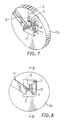
- FIGS. 2 to 13 shown therein is apparatus for manufacturing the molding M.
- the apparatus includes a molding die D comprising a first disk-like molding die part D1, a second disk-like molding die part D2 and a third disk-like molding die part D3 which are closely positioned in this order.
- the first die part D1 is centrally formed with a long opening 1 through which the hard rubber R1 is to be supplied.
- the opening 1 is configured substantially to the sectional configuration of the first portion M1 of the molding M.
- the first die part D1 is also provided with a core member 10 which is positioned adjacent to the opening 1 and is forwardly projected from the front surface of the die part D1.
- the sectional configuration of the core member 10 is configured substantially to the sectional configuration of the bore B of the molding M.
- the upper position of the die part D1 is formed with a groove 2 through which the sponge rubber R2 is to be supplied. As best shown in FIG. 5, the groove 2 is branched to three thin grooves 2a.
- the die part D1 is also formed with a plurality of through holes 3 into which the hard rubber is to be introduced. The through holes 3 are arranged in two rows each of which is positioned between the thin grooves 2a.
- the second die part D2 is formed with an opening 4 which is adapted to closely receive the core member 10 therein.
- the die part D2 is also formed with an opening 5 which communicates with the opening 4 at the upper side thereof and has a configuration identical with that of the opening 1 of the first die part D1.
- the rear surface of the die part D2 is formed with a tapered recess 6 which is to be faced to the thin grooves 2a and the through holes 3 so as to receive the sponge rubber R2 and the hard rubber R1 supplied from the grooves 2a and the through holes 3.
- the front surface of the die part D2 is formed with a recess 7 which communicates with the tapered recess 6.
- the recess 7 communicates with the right half of the opening 4 through a guide recess 8 formed on the front surface of the die part D2.
- the front surface of the die part D2 is also formed with a groove 9 through which the sponge rubber R2 is to be supplied.
- the groove 9 communicates with the left half of the opening 4.
- the third part D3 is formed with an opening 11 which is configured to conform substantially to the outer configuration of the molding M to be formed.
- the die parts D1, D2, D3 are assembled in this order to form the molding die D, where the core member 10 is closely received with the opening 4 of the second die part D2 and is projected into the opening 11 of the third die part D3, thereby to form an annular extruding opening 11a which is configured to conform to the sectional configuration of the molding M.
- the molding die D is mounted on a head H of an extruder (not shown) to form the apparatus for manufacturing the molding M.
- the extruder includes a feed pipe 21 of the hard rubber R1 and a feed pipe 22 of the sponge rubber R2.
- the opening 1 of the first die part D1 and the opening 5 of the second die part D2 cooperate to form a first flow conduit C1 which communicates with the feed pipe 21 to permit the hard rubber R1 to flow toward the extruding opening 11a.
- the groove 9 communicates with the feed pipe 22 and acts as a second flow conduit C2 for flowing the sponge rubber R2 toward the extruding opening 11a.
- the tapered recess 6, the recess 7 and the guide recess 8 of the second die part D2 cooperate to form a third flow conduit C3 which communicates with both of the feed pipes 21, 22 through the through holes 3, the groove 2 and the thin grooves 2a, respectively, to permit the hard and sponge rubber R1, R2 to flow toward the extruding opening 11a.
- the molding M is manufactured by the above-described apparatus.
- the hard rubber R1 and sponge rubber R2 are simultaneously fed from the feed pipe 21, 22 and are distributed over the flow conduits C1, C2, C3.
- a part of the hard rubber R1 fed from the feed pipe 21 is introduced into the first conduit C1 and is directly extruded from the extruding opening 11a to form the first portion M1 of the molding M.
- a part of the sponge rubber R2 fed from the feed pipe 22 is introduced into the second conduit C2 and is directly extruded from the extruding opening 11a to form the second portion M2 of the molding M.
- the remainder of the hard rubber R1 fed from the feed pipe 21 is introduced into the third conduit C3 through the through holes 3.
- the remainder of the sponge rubber R2 fed from the feed pipe 22 is introduced into the third conduit C3 through the groove 2 and the thin grooves 2a.
- the hard and sponge rubber R1, R2 introduced into the third conduit C3 are effectively combined and are subsequently extruded from the extruding opening 11a to form the third portions M3 of the molding M.
- the hard and sponge rubber R1, R2 are introduced into the tapered recess 6 in two rows of stick-like form and in three layers of strip-like form, respectively, as shown in FIG. 13a.
- the hard and sponge rubber R1, R2 are gradually compressed in the tapered recess 6 and are advanced to the recess 7 where the rubber R1, R2 are formed to hybrid R3, as shown in FIG. 13b.
- the hybrid R3 is extruded from the extruding opening 11a through the guide recess 8 to form the third portions M3 of the molding M where the sectional configuration of the hard rubber R1 of the hybrid R3 is deformed along imaginary arcuate surfaces 23a, 23b concentrical with the arcuate surface of the third portion M3, as shown in FIG. 13C.
- the molding M comprising the three portions M1, M2, M3 which are formed of three types of material R1, R2, R3, respectively, and which are integrally formed as a unit, is effectively formed-in only one extruding process. Since the hard and sponge rubber R1, R2 are simultaneously fed from the feed pipes 21, 22, the three portions M1, M2, M3 are fixedly bonded to one another and the hard and sponge rubber R1, R2 of the hybrid R3 are also fixedly bonded to each other.
- the preferred embodiment herein described can be modified, if required.
- the configuration, the arrangement and the number of the thin grooves 2a and the through holes 3 can be modified to change the properties of the hybrid R3.
- a weather strip of an automobile can be easily formed.
- a weather strip S of an automobile mainly comprises an engagement member 33 which is to be mounted on an automobile body 36 and a tubular sealing member 34 which is to be contacted to an automobile door 37 when the door 37 is closed.
- These members 33 and 34 are formed of hard rubber and sponge rubber, respectively, and are integrally formed as a unit.
- the weather strip S generally includes a lip member 31 of which the lower surface is to be received with one end 32a of an interior decoration member 32.
- the lip member 31 is integrally formed to the engagement member 33.
- the lip member 31 is formed of hybrid of the hard rubber and the sponge rubber.
- the numeral 35 shows an ornamental covering member having a color identical with that of the interior decoration member 32.
Landscapes
- Engineering & Computer Science (AREA)
- Mechanical Engineering (AREA)
- Manufacturing & Machinery (AREA)
- Seal Device For Vehicle (AREA)
- Extrusion Moulding Of Plastics Or The Like (AREA)
- Vehicle Waterproofing, Decoration, And Sanitation Devices (AREA)
- Molding Of Porous Articles (AREA)
Applications Claiming Priority (2)
| Application Number | Priority Date | Filing Date | Title |
|---|---|---|---|
| JP119475/90 | 1990-05-09 | ||
| JP2119475A JP2931036B2 (ja) | 1990-05-09 | 1990-05-09 | シール材、並びにその成形方法及び装置 |
Publications (3)
| Publication Number | Publication Date |
|---|---|
| EP0456483A2 true EP0456483A2 (de) | 1991-11-13 |
| EP0456483A3 EP0456483A3 (en) | 1992-03-25 |
| EP0456483B1 EP0456483B1 (de) | 1995-02-01 |
Family
ID=14762227
Family Applications (1)
| Application Number | Title | Priority Date | Filing Date |
|---|---|---|---|
| EP91304156A Expired - Lifetime EP0456483B1 (de) | 1990-05-09 | 1991-05-09 | Geformte Dichtungsleiste und Vorrichtung und Verfahren zu ihrer Herstellung |
Country Status (4)
| Country | Link |
|---|---|
| US (1) | US5124189A (de) |
| EP (1) | EP0456483B1 (de) |
| JP (1) | JP2931036B2 (de) |
| DE (1) | DE69107114T2 (de) |
Cited By (1)
| Publication number | Priority date | Publication date | Assignee | Title |
|---|---|---|---|---|
| EP0528560A1 (de) * | 1991-07-30 | 1993-02-24 | Kinugawa Rubber Ind. Co., Ltd. | Kombinierte Extruderkopf Anordnung zur Herstellung eines Dichtungsstreifens |
Families Citing this family (4)
| Publication number | Priority date | Publication date | Assignee | Title |
|---|---|---|---|---|
| US6237966B1 (en) * | 1998-07-02 | 2001-05-29 | Bidco Plastic Extrusion, Inc. | Co-extruded dual durometer hardness pipe gasket |
| JP3861606B2 (ja) * | 2001-02-21 | 2006-12-20 | 豊田合成株式会社 | 自動車用ウエザストリップ |
| JP2006304387A (ja) * | 2005-04-15 | 2006-11-02 | Yazaki Corp | シール部材及び該シール部材を備えたグロメット |
| CN102941662B (zh) * | 2012-11-23 | 2015-02-25 | 深圳市飞荣达科技股份有限公司 | 一种多腔复合橡胶条挤出模具 |
Citations (4)
| Publication number | Priority date | Publication date | Assignee | Title |
|---|---|---|---|---|
| DE1817182A1 (de) * | 1967-12-28 | 1969-07-10 | Rasmussen O B | Verfahren zum Herstellen von synthetischen Folienmaterialien |
| DE3229554C1 (de) * | 1982-08-07 | 1984-03-15 | Hoechst Ag, 6230 Frankfurt | Verfahren und Vorrichtung zur Herstellung coextrudierter mehrschichtiger Verbundfolien aus thermoplastischen Kunststoffen |
| EP0209453A1 (de) * | 1985-07-19 | 1987-01-21 | Hutchinson | Verfahren zur Herstellung von Profilen durch Koextrusion, die mindestens zwei Teile mit verschiedenen Eigenschaften haben |
| EP0337719A2 (de) * | 1988-04-12 | 1989-10-18 | Jsp Corporation | Verfahren zur Herstellung einer thermoplastischen Kunststoffolie und deren Verwendung als Puffermaterial |
Family Cites Families (2)
| Publication number | Priority date | Publication date | Assignee | Title |
|---|---|---|---|---|
| US4898760A (en) * | 1987-11-17 | 1990-02-06 | Amesbury Industries, Inc. | Process and apparatus for extruding a low density elastomeric thermoplastic foam |
| US5013379A (en) * | 1988-01-25 | 1991-05-07 | Gencorp Inc. | Cohesive bonding process for forming a laminate of a wear resistant thermoplastic and a weather resistant rubber |
-
1990
- 1990-05-09 JP JP2119475A patent/JP2931036B2/ja not_active Expired - Lifetime
-
1991
- 1991-05-06 US US07/695,982 patent/US5124189A/en not_active Expired - Fee Related
- 1991-05-09 EP EP91304156A patent/EP0456483B1/de not_active Expired - Lifetime
- 1991-05-09 DE DE69107114T patent/DE69107114T2/de not_active Expired - Fee Related
Patent Citations (4)
| Publication number | Priority date | Publication date | Assignee | Title |
|---|---|---|---|---|
| DE1817182A1 (de) * | 1967-12-28 | 1969-07-10 | Rasmussen O B | Verfahren zum Herstellen von synthetischen Folienmaterialien |
| DE3229554C1 (de) * | 1982-08-07 | 1984-03-15 | Hoechst Ag, 6230 Frankfurt | Verfahren und Vorrichtung zur Herstellung coextrudierter mehrschichtiger Verbundfolien aus thermoplastischen Kunststoffen |
| EP0209453A1 (de) * | 1985-07-19 | 1987-01-21 | Hutchinson | Verfahren zur Herstellung von Profilen durch Koextrusion, die mindestens zwei Teile mit verschiedenen Eigenschaften haben |
| EP0337719A2 (de) * | 1988-04-12 | 1989-10-18 | Jsp Corporation | Verfahren zur Herstellung einer thermoplastischen Kunststoffolie und deren Verwendung als Puffermaterial |
Non-Patent Citations (1)
| Title |
|---|
| SOVIET PATENTS ABSTRACTS Section Ch, Week 8505, 13 March 1985 Derwent Publications Ltd., London, GB; Class A, AN 85-029559/05 & SU-A-555 605 (V.A. ANUFRIEV) 7 July 1984 * |
Cited By (2)
| Publication number | Priority date | Publication date | Assignee | Title |
|---|---|---|---|---|
| EP0528560A1 (de) * | 1991-07-30 | 1993-02-24 | Kinugawa Rubber Ind. Co., Ltd. | Kombinierte Extruderkopf Anordnung zur Herstellung eines Dichtungsstreifens |
| US5267846A (en) * | 1991-07-30 | 1993-12-07 | Kinugawa Rubber Ind. Co., Ltd. | Device for producing weather strip |
Also Published As
| Publication number | Publication date |
|---|---|
| EP0456483B1 (de) | 1995-02-01 |
| DE69107114D1 (de) | 1995-03-16 |
| JPH0416334A (ja) | 1992-01-21 |
| DE69107114T2 (de) | 1995-08-03 |
| JP2931036B2 (ja) | 1999-08-09 |
| US5124189A (en) | 1992-06-23 |
| EP0456483A3 (en) | 1992-03-25 |
Similar Documents
| Publication | Publication Date | Title |
|---|---|---|
| US5087488A (en) | Method and apparatus for forming a plastic article with an overlay of varying thickness having a shaded color appearance | |
| US4118166A (en) | Extrusion apparatus | |
| EP0774332A3 (de) | Verfahren und Vorrichtung zum Granulieren von Strängen aus thermoplastischen Kunststoffen | |
| JP3019729B2 (ja) | ウエザストリップの押出成形方法及び押出成形装置 | |
| EP0456483A2 (de) | Geformte Dichtungsleiste und Vorrichtung und Verfahren zu ihrer Herstellung | |
| US7258827B2 (en) | Method for extruding unvulcanized rubber | |
| US5250248A (en) | Apparatus and process for manufacturing a molding | |
| US6739599B1 (en) | Molding and method and device for manufacturing the molding | |
| US4187270A (en) | Extrusion apparatus | |
| JPH01127432A (ja) | 車両用の装飾モールデイングとその製法 | |
| EP0674986A4 (de) | Verfahren zum anbringen eines abschlussteils an einen flansch eines panels. | |
| EP0897787A3 (de) | Mehrfarbige Verbundfolie aus thermoplastischem Kunststoff und Verfahren und Vorrichtung für ihre Herstellung | |
| JP3507017B2 (ja) | ベルトモールの製造方法 | |
| JPS58108122A (ja) | ウエザ−ストリツプの製造方法 | |
| JP2554598B2 (ja) | 合成樹脂製ブロー成形管 | |
| JPS5448861A (en) | Multiple simultaneous extrusion coater | |
| CN216832104U (zh) | 一种含骨架类汽车密封条产品一模双腔挤出模具 | |
| JPH01204713A (ja) | モールディングの製造方法 | |
| JPH07718U (ja) | 押出型 | |
| JPH01204714A (ja) | モールディングの製造方法 | |
| GB2309662A (en) | Moulding a frame around a panel | |
| JPH0617056B2 (ja) | エアダクトの製造装置 | |
| JP3056595B2 (ja) | 長手方向に中空部を有する物品の製造方法 | |
| JPH06134838A (ja) | 着色梨地状表面を有する自動車用ウェザストリップの製造方法 | |
| JP3065437B2 (ja) | 長手方向に中空部を有する物品の製造方法 |
Legal Events
| Date | Code | Title | Description |
|---|---|---|---|
| PUAI | Public reference made under article 153(3) epc to a published international application that has entered the european phase |
Free format text: ORIGINAL CODE: 0009012 |
|
| AK | Designated contracting states |
Kind code of ref document: A2 Designated state(s): DE FR GB |
|
| PUAL | Search report despatched |
Free format text: ORIGINAL CODE: 0009013 |
|
| AK | Designated contracting states |
Kind code of ref document: A3 Designated state(s): DE FR GB |
|
| 17P | Request for examination filed |
Effective date: 19920514 |
|
| 17Q | First examination report despatched |
Effective date: 19931014 |
|
| GRAA | (expected) grant |
Free format text: ORIGINAL CODE: 0009210 |
|
| AK | Designated contracting states |
Kind code of ref document: B1 Designated state(s): DE FR GB |
|
| REF | Corresponds to: |
Ref document number: 69107114 Country of ref document: DE Date of ref document: 19950316 |
|
| ET | Fr: translation filed | ||
| PLBE | No opposition filed within time limit |
Free format text: ORIGINAL CODE: 0009261 |
|
| STAA | Information on the status of an ep patent application or granted ep patent |
Free format text: STATUS: NO OPPOSITION FILED WITHIN TIME LIMIT |
|
| 26N | No opposition filed | ||
| PGFP | Annual fee paid to national office [announced via postgrant information from national office to epo] |
Ref country code: DE Payment date: 19990507 Year of fee payment: 9 |
|
| PGFP | Annual fee paid to national office [announced via postgrant information from national office to epo] |
Ref country code: FR Payment date: 19990511 Year of fee payment: 9 |
|
| PGFP | Annual fee paid to national office [announced via postgrant information from national office to epo] |
Ref country code: GB Payment date: 19990512 Year of fee payment: 9 |
|
| PG25 | Lapsed in a contracting state [announced via postgrant information from national office to epo] |
Ref country code: GB Free format text: LAPSE BECAUSE OF NON-PAYMENT OF DUE FEES Effective date: 20000509 |
|
| GBPC | Gb: european patent ceased through non-payment of renewal fee |
Effective date: 20000509 |
|
| PG25 | Lapsed in a contracting state [announced via postgrant information from national office to epo] |
Ref country code: FR Free format text: LAPSE BECAUSE OF NON-PAYMENT OF DUE FEES Effective date: 20010131 |
|
| PG25 | Lapsed in a contracting state [announced via postgrant information from national office to epo] |
Ref country code: DE Free format text: LAPSE BECAUSE OF NON-PAYMENT OF DUE FEES Effective date: 20010301 |
|
| REG | Reference to a national code |
Ref country code: FR Ref legal event code: ST |