EP0455152B1 - Verfahren zur Reinigung von Abgasen - Google Patents
Verfahren zur Reinigung von Abgasen Download PDFInfo
- Publication number
- EP0455152B1 EP0455152B1 EP91106765A EP91106765A EP0455152B1 EP 0455152 B1 EP0455152 B1 EP 0455152B1 EP 91106765 A EP91106765 A EP 91106765A EP 91106765 A EP91106765 A EP 91106765A EP 0455152 B1 EP0455152 B1 EP 0455152B1
- Authority
- EP
- European Patent Office
- Prior art keywords
- zeolites
- pic
- process according
- adsorption
- exhaust gases
- Prior art date
- Legal status (The legal status is an assumption and is not a legal conclusion. Google has not performed a legal analysis and makes no representation as to the accuracy of the status listed.)
- Expired - Lifetime
Links
- 238000000034 method Methods 0.000 title claims abstract description 33
- 238000000746 purification Methods 0.000 title claims abstract description 6
- 239000007789 gas Substances 0.000 title claims description 55
- 239000010457 zeolite Substances 0.000 claims abstract description 111
- 238000001179 sorption measurement Methods 0.000 claims abstract description 29
- 238000002485 combustion reaction Methods 0.000 claims abstract description 11
- 238000001914 filtration Methods 0.000 claims abstract description 7
- 239000004744 fabric Substances 0.000 claims description 13
- 150000001768 cations Chemical class 0.000 claims description 10
- 150000002013 dioxins Chemical class 0.000 claims description 9
- 150000002240 furans Chemical class 0.000 claims description 7
- 239000000428 dust Substances 0.000 claims description 5
- -1 silver ions Chemical class 0.000 claims description 5
- 229910052709 silver Inorganic materials 0.000 claims description 4
- 239000004332 silver Substances 0.000 claims description 4
- 239000003795 chemical substances by application Substances 0.000 claims description 3
- 239000001301 oxygen Substances 0.000 claims description 3
- 229910052760 oxygen Inorganic materials 0.000 claims description 3
- QVGXLLKOCUKJST-UHFFFAOYSA-N atomic oxygen Chemical compound [O] QVGXLLKOCUKJST-UHFFFAOYSA-N 0.000 claims description 2
- 239000011261 inert gas Substances 0.000 claims description 2
- 239000002243 precursor Substances 0.000 claims description 2
- 229910001415 sodium ion Inorganic materials 0.000 claims 2
- 230000002950 deficient Effects 0.000 claims 1
- 239000003463 adsorbent Substances 0.000 abstract description 18
- OKTJSMMVPCPJKN-UHFFFAOYSA-N Carbon Chemical compound [C] OKTJSMMVPCPJKN-UHFFFAOYSA-N 0.000 abstract description 15
- 231100000331 toxic Toxicity 0.000 abstract description 14
- 230000002588 toxic effect Effects 0.000 abstract description 14
- 239000011148 porous material Substances 0.000 abstract description 11
- 239000000571 coke Substances 0.000 abstract description 8
- 238000004056 waste incineration Methods 0.000 abstract description 8
- 239000002912 waste gas Substances 0.000 abstract description 6
- 239000003077 lignite Substances 0.000 abstract description 5
- AXCZMVOFGPJBDE-UHFFFAOYSA-L calcium dihydroxide Chemical compound [OH-].[OH-].[Ca+2] AXCZMVOFGPJBDE-UHFFFAOYSA-L 0.000 abstract description 4
- 229910001861 calcium hydroxide Inorganic materials 0.000 abstract description 4
- 239000000920 calcium hydroxide Substances 0.000 abstract description 4
- 239000003546 flue gas Substances 0.000 abstract description 4
- 239000000203 mixture Substances 0.000 abstract description 4
- XLYOFNOQVPJJNP-UHFFFAOYSA-N water Substances O XLYOFNOQVPJJNP-UHFFFAOYSA-N 0.000 abstract description 4
- 229910001868 water Inorganic materials 0.000 abstract description 4
- 230000000694 effects Effects 0.000 abstract description 2
- 239000010801 sewage sludge Substances 0.000 abstract description 2
- 230000008030 elimination Effects 0.000 abstract 1
- 238000003379 elimination reaction Methods 0.000 abstract 1
- 238000004140 cleaning Methods 0.000 description 15
- HNPSIPDUKPIQMN-UHFFFAOYSA-N dioxosilane;oxo(oxoalumanyloxy)alumane Chemical group O=[Si]=O.O=[Al]O[Al]=O HNPSIPDUKPIQMN-UHFFFAOYSA-N 0.000 description 13
- 229910021536 Zeolite Inorganic materials 0.000 description 11
- 238000003795 desorption Methods 0.000 description 6
- 238000007664 blowing Methods 0.000 description 5
- 239000003054 catalyst Substances 0.000 description 5
- 239000003344 environmental pollutant Substances 0.000 description 5
- 229910052753 mercury Inorganic materials 0.000 description 5
- 229910052751 metal Inorganic materials 0.000 description 5
- 239000002184 metal Substances 0.000 description 5
- 231100000719 pollutant Toxicity 0.000 description 5
- 150000003839 salts Chemical class 0.000 description 5
- QSHDDOUJBYECFT-UHFFFAOYSA-N mercury Chemical compound [Hg] QSHDDOUJBYECFT-UHFFFAOYSA-N 0.000 description 4
- 150000002739 metals Chemical class 0.000 description 4
- 238000000926 separation method Methods 0.000 description 4
- UHOVQNZJYSORNB-UHFFFAOYSA-N Benzene Chemical compound C1=CC=CC=C1 UHOVQNZJYSORNB-UHFFFAOYSA-N 0.000 description 3
- YXFVVABEGXRONW-UHFFFAOYSA-N Toluene Chemical compound CC1=CC=CC=C1 YXFVVABEGXRONW-UHFFFAOYSA-N 0.000 description 3
- 230000015572 biosynthetic process Effects 0.000 description 3
- 235000011116 calcium hydroxide Nutrition 0.000 description 3
- 239000010881 fly ash Substances 0.000 description 3
- 229910001385 heavy metal Inorganic materials 0.000 description 3
- 239000002808 molecular sieve Substances 0.000 description 3
- URGAHOPLAPQHLN-UHFFFAOYSA-N sodium aluminosilicate Chemical compound [Na+].[Al+3].[O-][Si]([O-])=O.[O-][Si]([O-])=O URGAHOPLAPQHLN-UHFFFAOYSA-N 0.000 description 3
- 238000005979 thermal decomposition reaction Methods 0.000 description 3
- 238000010626 work up procedure Methods 0.000 description 3
- QGZKDVFQNNGYKY-UHFFFAOYSA-N Ammonia Chemical compound N QGZKDVFQNNGYKY-UHFFFAOYSA-N 0.000 description 2
- IJGRMHOSHXDMSA-UHFFFAOYSA-N Atomic nitrogen Chemical compound N#N IJGRMHOSHXDMSA-UHFFFAOYSA-N 0.000 description 2
- UGFAIRIUMAVXCW-UHFFFAOYSA-N Carbon monoxide Chemical compound [O+]#[C-] UGFAIRIUMAVXCW-UHFFFAOYSA-N 0.000 description 2
- XUIMIQQOPSSXEZ-UHFFFAOYSA-N Silicon Chemical group [Si] XUIMIQQOPSSXEZ-UHFFFAOYSA-N 0.000 description 2
- BQCADISMDOOEFD-UHFFFAOYSA-N Silver Chemical compound [Ag] BQCADISMDOOEFD-UHFFFAOYSA-N 0.000 description 2
- 229910052793 cadmium Inorganic materials 0.000 description 2
- 229910052799 carbon Inorganic materials 0.000 description 2
- 230000015556 catabolic process Effects 0.000 description 2
- 230000006378 damage Effects 0.000 description 2
- 238000006298 dechlorination reaction Methods 0.000 description 2
- 238000006731 degradation reaction Methods 0.000 description 2
- 229910001882 dioxygen Inorganic materials 0.000 description 2
- 238000010438 heat treatment Methods 0.000 description 2
- 229930195733 hydrocarbon Natural products 0.000 description 2
- 238000011068 loading method Methods 0.000 description 2
- 238000004064 recycling Methods 0.000 description 2
- 238000011144 upstream manufacturing Methods 0.000 description 2
- 206010010774 Constipation Diseases 0.000 description 1
- 241001076195 Lampsilis ovata Species 0.000 description 1
- 208000036758 Postinfectious cerebellitis Diseases 0.000 description 1
- 239000013543 active substance Substances 0.000 description 1
- 230000006978 adaptation Effects 0.000 description 1
- 239000000654 additive Substances 0.000 description 1
- 230000000996 additive effect Effects 0.000 description 1
- 239000003513 alkali Substances 0.000 description 1
- AZDRQVAHHNSJOQ-UHFFFAOYSA-N alumane Chemical group [AlH3] AZDRQVAHHNSJOQ-UHFFFAOYSA-N 0.000 description 1
- 229910052782 aluminium Inorganic materials 0.000 description 1
- XAGFODPZIPBFFR-UHFFFAOYSA-N aluminium Chemical compound [Al] XAGFODPZIPBFFR-UHFFFAOYSA-N 0.000 description 1
- 229910000323 aluminium silicate Inorganic materials 0.000 description 1
- 229910021529 ammonia Inorganic materials 0.000 description 1
- BDOSMKKIYDKNTQ-UHFFFAOYSA-N cadmium atom Chemical compound [Cd] BDOSMKKIYDKNTQ-UHFFFAOYSA-N 0.000 description 1
- 230000003197 catalytic effect Effects 0.000 description 1
- 239000003245 coal Substances 0.000 description 1
- 229910052802 copper Inorganic materials 0.000 description 1
- 239000013078 crystal Substances 0.000 description 1
- 238000000354 decomposition reaction Methods 0.000 description 1
- 239000003599 detergent Substances 0.000 description 1
- 238000001035 drying Methods 0.000 description 1
- 230000007717 exclusion Effects 0.000 description 1
- 239000012013 faujasite Substances 0.000 description 1
- 238000010304 firing Methods 0.000 description 1
- 239000008187 granular material Substances 0.000 description 1
- 239000002920 hazardous waste Substances 0.000 description 1
- 229910001387 inorganic aluminate Inorganic materials 0.000 description 1
- 229910052909 inorganic silicate Inorganic materials 0.000 description 1
- 150000002500 ions Chemical class 0.000 description 1
- 229910052745 lead Inorganic materials 0.000 description 1
- 230000007257 malfunction Effects 0.000 description 1
- 238000004519 manufacturing process Methods 0.000 description 1
- 229910052757 nitrogen Inorganic materials 0.000 description 1
- 230000035515 penetration Effects 0.000 description 1
- 230000001105 regulatory effect Effects 0.000 description 1
- 238000005201 scrubbing Methods 0.000 description 1
- 150000004760 silicates Chemical class 0.000 description 1
- 229910052710 silicon Inorganic materials 0.000 description 1
- 239000010703 silicon Substances 0.000 description 1
- 229910052979 sodium sulfide Inorganic materials 0.000 description 1
- GRVFOGOEDUUMBP-UHFFFAOYSA-N sodium sulfide (anhydrous) Chemical compound [Na+].[Na+].[S-2] GRVFOGOEDUUMBP-UHFFFAOYSA-N 0.000 description 1
- 239000000126 substance Substances 0.000 description 1
- 231100000925 very toxic Toxicity 0.000 description 1
- 229910052725 zinc Inorganic materials 0.000 description 1
Images
Classifications
-
- B—PERFORMING OPERATIONS; TRANSPORTING
- B01—PHYSICAL OR CHEMICAL PROCESSES OR APPARATUS IN GENERAL
- B01J—CHEMICAL OR PHYSICAL PROCESSES, e.g. CATALYSIS OR COLLOID CHEMISTRY; THEIR RELEVANT APPARATUS
- B01J20/00—Solid sorbent compositions or filter aid compositions; Sorbents for chromatography; Processes for preparing, regenerating or reactivating thereof
- B01J20/02—Solid sorbent compositions or filter aid compositions; Sorbents for chromatography; Processes for preparing, regenerating or reactivating thereof comprising inorganic material
- B01J20/10—Solid sorbent compositions or filter aid compositions; Sorbents for chromatography; Processes for preparing, regenerating or reactivating thereof comprising inorganic material comprising silica or silicate
- B01J20/16—Alumino-silicates
- B01J20/18—Synthetic zeolitic molecular sieves
-
- B—PERFORMING OPERATIONS; TRANSPORTING
- B01—PHYSICAL OR CHEMICAL PROCESSES OR APPARATUS IN GENERAL
- B01D—SEPARATION
- B01D53/00—Separation of gases or vapours; Recovering vapours of volatile solvents from gases; Chemical or biological purification of waste gases, e.g. engine exhaust gases, smoke, fumes, flue gases, aerosols
- B01D53/02—Separation of gases or vapours; Recovering vapours of volatile solvents from gases; Chemical or biological purification of waste gases, e.g. engine exhaust gases, smoke, fumes, flue gases, aerosols by adsorption, e.g. preparative gas chromatography
-
- B—PERFORMING OPERATIONS; TRANSPORTING
- B01—PHYSICAL OR CHEMICAL PROCESSES OR APPARATUS IN GENERAL
- B01D—SEPARATION
- B01D2257/00—Components to be removed
- B01D2257/20—Halogens or halogen compounds
- B01D2257/206—Organic halogen compounds
Definitions
- the invention relates to a method for purifying exhaust gases according to the preamble of claim 1.
- PIC Process of Incomplete Combustion
- the PIC include about dioxins, furans and their precursors, some of which are very toxic and must not be emitted in small quantities.
- measures which prevent the formation of PIC or which reduce the resulting PIC again.
- measures are, for example, the improvement of the burnout or, as known from EP-A1-0 252 521, the degradation of the PIC in the presence of a catalyst at temperatures between 150 to 800 ° C.
- Degradation of PIC removed from the exhaust gas by attachment to the fly ash can, e.g. described in EP-A1 0 280 364, take place outside the cleaning process.
- a corresponding device for destroying the PIC in the fly ash is known from DE-OS 37 03 984.
- the filter stage consisting of an adsorber bed made of brown coal coke is e.g. arranged before denitrification and operated at temperatures of up to 150 ° C. If the exhaust gas is scrubbed wet, the entire brown coal coke can be disposed of in the furnace.
- brown coal coke A major disadvantage of using brown coal coke is the risk of self-ignition and smoldering fire. Another disadvantage of this method is that lignite coke loaded with toxic PIC has to be transported from the filter stage to the firing of the plant.
- adsorption / filtration for the separation of PIC ie polycyclic hydrocarbons, for example dioxins and furans
- PIC polycyclic hydrocarbons, for example dioxins and furans
- a filtering separator The adsorbent mixture separated in the filter is circulated and only slightly replaced by fresh additive.
- the partial quantity discharged from the recirculation circuit is led to the thermal decomposition of the PIC to the incineration plant.
- Substances with a high selectivity e.g. activated carbon, molecular sieves, sodium sulfide, hydrated lime
- adsorbents e.g. activated carbon, molecular sieves, sodium sulfide, hydrated lime
- the object of the invention is therefore to find and use the best available adsorbent in a method according to the preamble of claim 1, with which the PIC, in particular dioxins and furans, are removed as completely and safely as possible.
- the characterizing part of claim 1 solves this problem.
- Zeolites are made up of crystalline aluminosilicates, consisting of 4-valent silicon atoms and 3-valent aluminum atoms, which are integrated in an oxygen anion lattice. To neutralize the charge differences between silicon and aluminum, cations (K+, Na+, Ca2+, NH4+, etc.) are integrated in the crystal lattice.
- the zeolites contain polyhedra, layers or chains made of corner-linked AlO4 and SiO4 tetrahedra, which are connected to form a pore-rich spatial network with long channels. Inside are the alkali or alkaline earth ions. The channels form cavities, so-called active centers, with effective openings, the so-called pore openings, which, depending on the structure type and the cations used, have fixed values between 0.3 and 1.1 nm (3 and 11 ⁇ ).
- the cavities are connected to one another via these openings and can only be passed by molecules of suitable size and shape, which e.g. enables the separation of molecules of different sizes.
- the gas kinetic diameter of the molecules is decisive for the penetration. It must not be larger than the pore opening of the special zeolites. It must also not be significantly smaller than the pore opening, because otherwise no adsorption takes place.
- zeolites as adsorbents or as separating agents of different sized molecules is e.g. known from the magazine “Chemistry in our time", 4/86, pp. 117 to 127.
- DE-OS 39 19 124 describes the use of molecular sieves, in addition to e.g. Known from DE-PS 21 19 829, carbon-containing molecular sieves or other silicates also include zeolites, for the removal of pre-cleaned exhaust gas from polycyclic hydrocarbons.
- zeolites with a smaller pore opening an adsorption capacity for dioxins and furans had to be ruled out.
- the gas kinetic diameter of the dioxins and furans is not exactly known, but can be estimated on the basis of similar molecular structures.
- Suitable zeolites would then have a pore opening greater than 0.7 nm (7 ⁇ ) (benzene: 0.7 nm (7.0 ⁇ ), at about 100 ° C., Taschenbuch, pp. 3-264, see Table 4, Ullmann, Volume 17, P. 16) or even larger 0.74nm (7.4 ⁇ ) (toluene: 0.74nm (7.4 ⁇ ), at approx. 100 ° C, Paperback, pp. 3-264).
- the pore opening of the zeolites of structure type A is 0.3 to 0.5 nm (3 to 5 ⁇ ) depending on the cation, 0.41 nm (4.1 ⁇ ) for Na+. Structure type A zeolites are unlikely to have an adsorbing effect on the toxic PIC, such as dioxins and furans.
- these zeolites can reduce the toxic PIC, measured in TE (toxic units), in the exhaust gas by 99%, even if the exhaust gas has a high water content.
- the mechanism by which the toxic PICs are removed from the exhaust gas despite the expected loading of the active centers with the excess molecules in the exhaust gas and despite the pore opening being too small is not yet known.
- the dioxins are dechlorinated, which is likely to be associated with the destruction of the zeolite structure.
- zeolites also has the advantage in removing PIC that there is no longer any risk of self-ignition and a smoldering fire in the adsorber.
- zeolites can be used in the temperature range of 70 to 200 ° C, depending on the procedure of the cleaning system.
- the zeolites according to the invention have a specific surface area of 700 to 1500 m 2 / g, which is necessary to remove the PIC as completely as possible both with only small amounts in the exhaust gas and with a brief increase in their amount, e.g. due to operational disruptions. This increases operational reliability.
- zeolites also reduce the metals still in the exhaust gas, such as Hg, Cd, Pb, Zn, Cu, salts and other products from the cleaning process.
- the structure A zeolites used according to the invention are commercially available zeolites. They are therefore readily available.
- the zeolites of structure type A with Na+ as the cation described in claim 2 are customary, inexpensive detergent zeolites. As a result, the operating costs when using these zeolites are particularly low.
- the adsorption of mercury is further improved by amalgan formation.
- the advantage of claim 4 is that the adsorption can be carried out at higher temperatures and the zeolites are easier to handle in a configured form.
- the advantage of claim 5 is that in the case of adsorption in a fabric filter, a simple adaptation to different contents of PIC in the exhaust gas is possible by regulating the amount of adsorbent supplied and the layer thickness. 30 to 700 mg zeolites with a grain diameter of 1 to 100 »m are fed into the exhaust gas per m3. A particularly good filter layer is built up with zeolites with a grain diameter of 5 to 20 »m.
- the advantage of claim 6 is that the loaded zeolites are safely worked up. At a temperature of 250 to 500 ° C and exclusion of air there is a desorption of the pollutants adsorbed on the zeolite and at the same time a complete thermal decomposition of the PIC. Even at these higher temperatures required for processing, there is no fire risk when using zeolites.
- the processing of the zeolites also avoids the safety risk associated with transporting an adsorbent loaded with toxic PIC back to a combustion chamber, which is described in DE-OS 39 19 124.
- the advantage of claim 7 is that the desorption of the pollutants adsorbed on the zeolites is accelerated by the supply of a low-oxygen gas and thus the workup can be carried out more quickly.
- Advantage of claim 8 is a better utilization of the zeolites by direct recycling of part of the zeolites.
- part of the loaded zeolites is withdrawn, i.e. removed from the circulation. This is an advantageous sink for the remaining pollutants also accumulated in the loaded zeolites, such as heavy metals, salts and other products from the previous cleaning process.
- the method according to claim 9 would be particularly advantageous if, during the adsorption of the PIC on the zeolites, the toxic PIC is destroyed.
- the zeolites are only removed from the circuit after processing to form a sink, they are easier to dispose of. You can e.g. processed together with the fly ash, which may have already been pretreated.
- Claim 11 is advantageous in cleaning systems in which the exhaust gas comes from a combustion chamber with adjoining exhaust gas ducts.
- Claim 12 is advantageous in cleaning systems in which no return to a combustion chamber or in exhaust gas ducts is possible.
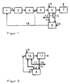
- Figure 1 shows a system for purifying exhaust gas with a zeolite adsorber of a first example
- Figure 2 shows a further embodiment of zeolite adsorber and device for processing the zeolites of a system of a second example.
- a system shown in Figure 1 for the purification of exhaust gases by a wet process of a waste incineration plant 1 has the following devices connected in series and connected by exhaust gas channels 2: a dust extractor 3, a two-stage scrubber 4 for removing HCl, HF and SO2, a catalyst 5 for removing NO x , a zeolite adsorber, which has a filter 6 with a bed of zeolite and a chimney 7.
- the system has a device 8 for processing the zeolites.
- a supply line 9 for fresh zeolites, a discharge line 10 for loaded zeolites, a feed line 11 branching off from the discharge line 10 for directly recycled, loaded zeolites and a feed line 12 for refurbished zeolites are connected to the filter 6.
- the discharge line 10 for loaded zeolites and the feed line 12 for refurbished zeolites are connected to the device 8 for refurbishing the zeolites.
- a line 13 branches off from the feed line 12 for withdrawing processed zeolites.
- a supply line 14 for low-oxygen gas opens into the device 8.
- an exhaust pipe 15 leads to the combustion chamber of the waste incineration plant 1.
- the packed bed of zeolites in the filter 6 has a thickness of 0.5 to 2 m and consists of granules with a grain diameter of 1 to 3 mm.
- the specific surface area of the zeolites used is 700 to 1500 m2 / g.
- zeolites of structure type A with Na+ as the cation i.e. with a pore opening of 0.41 nm (4.1 ⁇ ).
- the device 8 for processing the zeolites has a directly heated rotary drum.
- the exhaust gas first flows through the deduster 3, in which the flying dust is removed, then through the two-stage scrubber 4, in which HCl and HF are washed in the first stage and SO 2 in the second stage, then the catalyst 5, in which is removed after heating up the flue gas and injecting ammonia NO x , finally the filter 6 and leaves the system through the chimney 7.
- the exhaust gas flows through the packed bed of zeolites at a temperature of 80 to 200 ° C, in particular 120 to 200 ° C.
- the zeolites adsorb the i.a. PIC present in small amounts in the cleaned exhaust gas.
- clean gas values 0.007 ngTE / Nm3 were measured after the adsorption. This corresponds to a separation of> 99.8%.
- the large adsorption capacity of the zeolites also ensures that the PIC is largely completely adsorbed if its quantity in the exhaust gas is increased due to a malfunction.
- the zeolites adsorb residual salts and other products from the previous cleaning stages, but also, if present, mercury, HCl, HF, SO2, in particular dusty and gaseous metals.
- 20 to 100% of the loaded zeolites are passed through the discharge line 10 into the device 8 for processing the zeolites and there, in the absence of air, from an oxygen-poor, hot gas introduced through the supply line 14, e.g. Steam or inert gas flows through, whereby a temperature of 250 to 500 ° C is set. Desorption of the pollutants attached to the zeolites takes place and at the same time decomposition of the PIC.
- an oxygen-poor, hot gas introduced through the supply line 14, e.g. Steam or inert gas flows through, whereby a temperature of 250 to 500 ° C is set.
- Desorption of the pollutants attached to the zeolites takes place and at the same time decomposition of the PIC.
- the rest of the loaded zeolites are returned directly to the filter 6 through the feed line 11 for better utilization of the zeolites.
- 5 to 50% of the processed zeolites are deducted, i.e. discharged from the system through line 13 and e.g. deposited. They serve as a sink for the remaining pollutants also accumulated in the zeolites, such as heavy metals, salts and other products from the cleaning process.
- the rest of the processed zeolites are fed back into the filter 6 through the feed line 12.
- the exhaust gas from the device 8 for processing the zeolites is returned to the combustion chamber of the waste incineration plant 1 via the exhaust pipe 15.
- the zeolites drawn off can also be returned to the combustion chamber for complete inertization of the adsorbent.
- the exhaust gas of the device 8 can also be returned directly to one of the exhaust gas channels 2, for example upstream of the scrubber 4 or upstream of the catalytic converter 5, as is indicated by an exhaust line 15 shown in dashed lines in FIG. 1.
- the system could also be equipped with another device for removing NO x , such as a special activated carbon filter.
- the zeolite adsorber (both the zeolite adsorber of this example 1 and that of example 2) could also be arranged behind a plant for purifying the exhaust gas by a dry or quasi-dry process.
- the scrubber 4 there is first a heating device and then the zeolite adsorber formed by the filter 6 in front of the catalyst 5 and the chimney 7. In operation, the exhaust gas leaving scrubber 4 is first warmed up by 5 to 60 ° C. before it is passed into filter 6 for adsorption of the PIC.
- Example 2 (no example to explain the method according to the invention)
- the system of example 2 has a zeolite adsorber with a blowing device 16 and a fabric filter 17.
- the feed line 9 for fresh zeolites, the feed line 11 for directly recycled, loaded zeolites and the feed line 12 for refurbished zeolites are connected to the blowing device 16 and the discharge line 10 to the fabric filter 17.
- a line 18 branches off from the discharge line 10 for withdrawing loaded zeolites.
- the fabric filter 17 consists of 100 individually cleanable areas and is provided with a pulse cleaning system.
- the filter fabric used in the fabric filter 17 is suitable for surface filtration.
- the exhaust pipe 15 connects the device 8 for working up the zeolites with the zeolite adsorber.
- the device 8 has an indirectly heatable tube provided with a conveying device.
- pulverulent zeolites of the structure type faujasite with Na+ as cations (pore opening 0.74 nm (7.4 ⁇ )) with a grain diameter of 1 to 100 »m, in particular 5 to 20» m, are in the blowing device 16 into the Exhaust gas is blown in before the exhaust gas filters the fabric filter 17 at a flow velocity of 0.2 to 1 m / min, in particular 0.5 to 0.7 m / min, and at a temperature, for example Flows through 130 °.
- Surface filtering of the zeolites initially takes place in the fabric filter 17 until a filter layer has formed.
- the layer thickness is adjusted by a differential pressure control system to a value of 0.5 to 2 mm, in that the areas of the fabric filter 17 are cleaned one after the other each time the fabric filter 17 reaches a certain differential pressure. Cleaning air is supplied in countercurrent in pulses.
- the differential pressure triggering the cleaning is set between 15 and 30 mbar.
- the adsorption of the PIC and, presumably, its at least partial destruction begins when the zeolites are blown into the exhaust gas and preferably continues in the filter layer in the fabric filter 17. There is a separation of 99.5% of the toxic PIC measured in TE units.
- the zeolites adsorb residual salts and other products from the previous cleaning stages, but also, if present, mercury, HCl, HF, SO2, in particular dusty and gaseous metals.
- the loaded zeolites dissolved by the cleaning air are collected and led into the discharge line 10.
- the processed zeolites are fed back into the blowing device 16 through the feed line 12.
Landscapes
- Chemical & Material Sciences (AREA)
- Analytical Chemistry (AREA)
- Chemical Kinetics & Catalysis (AREA)
- Inorganic Chemistry (AREA)
- Organic Chemistry (AREA)
- Engineering & Computer Science (AREA)
- General Chemical & Material Sciences (AREA)
- Oil, Petroleum & Natural Gas (AREA)
- Treating Waste Gases (AREA)
- Solid-Sorbent Or Filter-Aiding Compositions (AREA)
- Incineration Of Waste (AREA)
- Fluidized-Bed Combustion And Resonant Combustion (AREA)
Applications Claiming Priority (2)
| Application Number | Priority Date | Filing Date | Title |
|---|---|---|---|
| DE4013768 | 1990-04-28 | ||
| DE4013768 | 1990-04-28 |
Publications (2)
| Publication Number | Publication Date |
|---|---|
| EP0455152A1 EP0455152A1 (de) | 1991-11-06 |
| EP0455152B1 true EP0455152B1 (de) | 1995-02-22 |
Family
ID=6405380
Family Applications (1)
| Application Number | Title | Priority Date | Filing Date |
|---|---|---|---|
| EP91106765A Expired - Lifetime EP0455152B1 (de) | 1990-04-28 | 1991-04-26 | Verfahren zur Reinigung von Abgasen |
Country Status (5)
| Country | Link |
|---|---|
| EP (1) | EP0455152B1 (da) |
| AT (1) | ATE118697T1 (da) |
| DE (2) | DE4113597C2 (da) |
| DK (1) | DK0455152T3 (da) |
| ES (1) | ES2069766T3 (da) |
Families Citing this family (11)
| Publication number | Priority date | Publication date | Assignee | Title |
|---|---|---|---|---|
| DE4128106C2 (de) * | 1991-08-24 | 1994-07-28 | Metallgesellschaft Ag | Verfahren zur Abtrennung von hochkondensierten, polyzyklischen Kohlenwasserstoffen aus Abgasen |
| DE4343607C2 (de) * | 1993-04-16 | 1996-03-21 | Alexander Michailow | Verfahren und Vorrichtung zum Reinigen von Luft |
| DE4413280C2 (de) * | 1994-04-16 | 1997-08-21 | Metallgesellschaft Ag | Verfahren und Vorrichtung zur Abtrennung von Dioxinen und Furanen aus dem Abgas eines Sinterprozesses |
| DE4429027C2 (de) * | 1994-08-16 | 1997-09-11 | Metallgesellschaft Ag | Verfahren zur Abtrennung von polycyclischen und polyhalogenierten Kohlenwasserstoffen, insbesondere von Dioxinen und Furanen, aus dem Abgas eines Sinterprozesses |
| US5968467A (en) * | 1995-09-22 | 1999-10-19 | Kurita Water Industries, Co., Ltd. | Dioxin formation preventative in incinerators and method for preventing the formation of dioxins |
| DE19617076A1 (de) * | 1996-04-29 | 1997-11-06 | Metallgesellschaft Ag | Verfahren zur Adsorption von Kohlenwasserstoffen aus Rauchgasen |
| DE19940683B4 (de) * | 1999-08-27 | 2005-08-18 | Rwe Power Ag | Verfahren zur trockenen Reinigung von Abgasen aus Sinteranlagen, Hüttenwerken oder sekundär metallurgischen Schmelzanlagen sowie staubförmiges Sorbens zur trockenen Reinigung solcher Abgase |
| US8282900B2 (en) * | 2007-02-21 | 2012-10-09 | Tosoh Corporation | Agent for rendering halogen-containing gas harmless, and method of rendering halogen-containing gas harmless using same |
| US20130042615A1 (en) * | 2011-08-18 | 2013-02-21 | Albert Calderon | Advanced method and apparatus for addressing the serious pollution from existing coal-burning power stations |
| CN113731101B (zh) * | 2020-05-28 | 2023-06-23 | 中冶长天国际工程有限责任公司 | 一种基于活性炭分离解析的垃圾焚烧烟气处理系统及烟气处理方法 |
| CN112057959B (zh) * | 2020-08-27 | 2022-06-24 | 泰安阳光天润化工工程有限公司 | 一种活性焦烟气净化吸附装置 |
Family Cites Families (8)
| Publication number | Priority date | Publication date | Assignee | Title |
|---|---|---|---|---|
| DE2829703C2 (de) * | 1978-07-06 | 1983-11-10 | Bayer Ag, 5090 Leverkusen | Verfahren zur Entfernung von NO aus sauerstofffreien Gasen mittels Zeolithen |
| US4374654A (en) * | 1981-08-03 | 1983-02-22 | Chevron Research Company | Absorptive separation of HCl and H2 S from catalytic reformer offgas |
| DE3602710A1 (de) * | 1986-01-30 | 1987-08-06 | Petersen Hugo Verfahrenstech | Verfahren zum regenerieren von mit schwefelsaeure und mit ammoniumsulfaten beladenem koernigem kohlenstoffhaltigem adsorptionsmittel |
| DE3623492A1 (de) * | 1986-07-11 | 1988-01-21 | Hagenmaier Hans Paul | Verfahren zum abbau von halogenierten aromaten |
| DE3706131A1 (de) * | 1987-02-26 | 1988-09-08 | Rheinische Braunkohlenw Ag | Verfahren zur entfernung von schadstoffen aus rauchgas |
| DE3718370A1 (de) * | 1987-06-02 | 1988-12-15 | Rennebeck Klaus | Verfahren und vorrichtung zur thermischen behandlung von katalysatoren |
| DE3843313A1 (de) * | 1988-12-22 | 1990-06-28 | Wacker Chemitronic | Verfahren zur entfernung von gasfoermigen kontaminierenden, insbesondere dotierstoffverbindungen aus halogensilanverbindungen enthaltenden traegergasen |
| DE3919124A1 (de) * | 1989-06-12 | 1990-01-18 | Haji Javad Mehdi Dr Ing | Verfahren zur abscheidung von polyzylkischen kohlenwasserstoffen und schwermetallen aus abgasen |
-
1991
- 1991-04-25 DE DE4113597A patent/DE4113597C2/de not_active Expired - Fee Related
- 1991-04-26 AT AT91106765T patent/ATE118697T1/de active
- 1991-04-26 EP EP91106765A patent/EP0455152B1/de not_active Expired - Lifetime
- 1991-04-26 ES ES91106765T patent/ES2069766T3/es not_active Expired - Lifetime
- 1991-04-26 DK DK91106765.0T patent/DK0455152T3/da active
- 1991-04-26 DE DE59104647T patent/DE59104647D1/de not_active Expired - Fee Related
Also Published As
| Publication number | Publication date |
|---|---|
| DE4113597C2 (de) | 1996-10-17 |
| ES2069766T3 (es) | 1995-05-16 |
| ATE118697T1 (de) | 1995-03-15 |
| DK0455152T3 (da) | 1995-05-29 |
| EP0455152A1 (de) | 1991-11-06 |
| DE4113597A1 (de) | 1991-10-31 |
| DE59104647D1 (de) | 1995-03-30 |
Similar Documents
| Publication | Publication Date | Title |
|---|---|---|
| EP0169997B1 (de) | Verfahren zur Reinigung von Rauchgas | |
| EP0666098B1 (de) | Verfahren zur Reinigung von Verbrennungsabgasen | |
| EP2125169B1 (de) | Verfahren und vorrichtung zum reinigen von abgasen eines sinterprozesses von erzen und/oder anderen metallhaltigen materialien in der metallerzeugung | |
| EP0553337B1 (de) | Verfahren zum reinigen von belasteten abgasen von verbrennungsanlagen | |
| EP0455152B1 (de) | Verfahren zur Reinigung von Abgasen | |
| DE4034498A1 (de) | Verfahren zur abtrennung von schwermetallen und dioxinen aus verbrennungsabgasen | |
| DE3921578A1 (de) | Verfahren zur reinigung von rauchgas aus verbrennungsanlagen | |
| DE4026071A1 (de) | Verfahren und anordnung zum reinigen von kohlenstoffhaltigem adsorptionsmittel | |
| EP0283721B2 (de) | Verfahren zum Entfernen von Schadstoffen aus Gas | |
| DE69620697T2 (de) | Verfahren zur Vermeidung der Dioxinbildung in Verbrennungsabgas | |
| EP0478744B1 (de) | Verfahren zur reinigung von abgasen, insbesondere aus abfallverbrennungsanlagen | |
| DE4128106C2 (de) | Verfahren zur Abtrennung von hochkondensierten, polyzyklischen Kohlenwasserstoffen aus Abgasen | |
| DE19824237A1 (de) | Reagentien für die Reinigung von Abgasen | |
| DE102015122230A1 (de) | Verfahren zur Abgasreinigung mittels eines Wirbelschichtströmungsreaktors | |
| DE4431558C2 (de) | Verfahren zur Entfernung von Schadstoffen aus Verbrennungsabgasen | |
| DE3605589C2 (de) | Verfahren und Vorrichtung zur Entfernung von Schwefeldioxid und Stickstoffoxiden aus Abgasen | |
| EP0476727B1 (de) | Verfahren zur Vermeidung der Bildung von hochkondensierten aromatischen Kohlenwasserstoffen und Dioxinen in Verbrennungsanlagen | |
| EP1020419A1 (de) | Verfahren zur Reinigung reduzierend wirkender Gase | |
| DE19940683B4 (de) | Verfahren zur trockenen Reinigung von Abgasen aus Sinteranlagen, Hüttenwerken oder sekundär metallurgischen Schmelzanlagen sowie staubförmiges Sorbens zur trockenen Reinigung solcher Abgase | |
| AT394102B (de) | Verfahren zum kombinierten abbau von organischen verbindungen und entfernung von hg, pb und cr aus staubfoermigen rueckstaenden thermischer entsorgungsprozesse | |
| EP2340885A1 (de) | Verfahren und Anlage zur Rauchgas-Reinigung | |
| AT393632B (de) | Verfahren zum abtrennen von verunreinigungen aus abgasen sowie vorrichtung zur durchfuehrung dieses verfahrens | |
| EP3781292B1 (de) | Verwertung von stickoxiden aus der umgebungsluft | |
| WO1993004765A1 (de) | Verfahren zur reinigung von rauchgas | |
| DE4119006A1 (de) | Verfahren zur zusaetzlichen entfernung von produkten unvollstaendiger verbrennung (pic) bei der reinigung von abgasen |
Legal Events
| Date | Code | Title | Description |
|---|---|---|---|
| PUAI | Public reference made under article 153(3) epc to a published international application that has entered the european phase |
Free format text: ORIGINAL CODE: 0009012 |
|
| 17P | Request for examination filed |
Effective date: 19910426 |
|
| AK | Designated contracting states |
Kind code of ref document: A1 Designated state(s): AT BE CH DE DK ES FR GB IT LI LU NL SE |
|
| RAP1 | Party data changed (applicant data changed or rights of an application transferred) |
Owner name: DEUTSCHE BABCOCK ANLAGEN GMBH |
|
| 17Q | First examination report despatched |
Effective date: 19930625 |
|
| GRAA | (expected) grant |
Free format text: ORIGINAL CODE: 0009210 |
|
| AK | Designated contracting states |
Kind code of ref document: B1 Designated state(s): AT BE CH DE DK ES FR GB IT LI LU NL SE |
|
| REF | Corresponds to: |
Ref document number: 118697 Country of ref document: AT Date of ref document: 19950315 Kind code of ref document: T |
|
| ITF | It: translation for a ep patent filed | ||
| REF | Corresponds to: |
Ref document number: 59104647 Country of ref document: DE Date of ref document: 19950330 |
|
| GBT | Gb: translation of ep patent filed (gb section 77(6)(a)/1977) |
Effective date: 19950317 |
|
| ET | Fr: translation filed | ||
| REG | Reference to a national code |
Ref country code: ES Ref legal event code: FG2A Ref document number: 2069766 Country of ref document: ES Kind code of ref document: T3 |
|
| REG | Reference to a national code |
Ref country code: DK Ref legal event code: T3 |
|
| PLBE | No opposition filed within time limit |
Free format text: ORIGINAL CODE: 0009261 |
|
| STAA | Information on the status of an ep patent application or granted ep patent |
Free format text: STATUS: NO OPPOSITION FILED WITHIN TIME LIMIT |
|
| 26N | No opposition filed | ||
| PGFP | Annual fee paid to national office [announced via postgrant information from national office to epo] |
Ref country code: SE Payment date: 19990119 Year of fee payment: 9 |
|
| PGFP | Annual fee paid to national office [announced via postgrant information from national office to epo] |
Ref country code: CH Payment date: 19990318 Year of fee payment: 9 |
|
| PGFP | Annual fee paid to national office [announced via postgrant information from national office to epo] |
Ref country code: ES Payment date: 19990413 Year of fee payment: 9 |
|
| PGFP | Annual fee paid to national office [announced via postgrant information from national office to epo] |
Ref country code: GB Payment date: 20000313 Year of fee payment: 10 |
|
| PGFP | Annual fee paid to national office [announced via postgrant information from national office to epo] |
Ref country code: NL Payment date: 20000320 Year of fee payment: 10 Ref country code: DK Payment date: 20000320 Year of fee payment: 10 |
|
| PGFP | Annual fee paid to national office [announced via postgrant information from national office to epo] |
Ref country code: AT Payment date: 20000322 Year of fee payment: 10 |
|
| PGFP | Annual fee paid to national office [announced via postgrant information from national office to epo] |
Ref country code: LU Payment date: 20000404 Year of fee payment: 10 |
|
| PG25 | Lapsed in a contracting state [announced via postgrant information from national office to epo] |
Ref country code: SE Free format text: LAPSE BECAUSE OF NON-PAYMENT OF DUE FEES Effective date: 20000427 Ref country code: ES Free format text: THE PATENT HAS BEEN ANNULLED BY A DECISION OF A NATIONAL AUTHORITY Effective date: 20000427 |
|
| PG25 | Lapsed in a contracting state [announced via postgrant information from national office to epo] |
Ref country code: LI Free format text: LAPSE BECAUSE OF NON-PAYMENT OF DUE FEES Effective date: 20000430 Ref country code: CH Free format text: LAPSE BECAUSE OF NON-PAYMENT OF DUE FEES Effective date: 20000430 |
|
| EUG | Se: european patent has lapsed |
Ref document number: 91106765.0 |
|
| REG | Reference to a national code |
Ref country code: CH Ref legal event code: PL |
|
| PGFP | Annual fee paid to national office [announced via postgrant information from national office to epo] |
Ref country code: DE Payment date: 20010312 Year of fee payment: 11 |
|
| PGFP | Annual fee paid to national office [announced via postgrant information from national office to epo] |
Ref country code: BE Payment date: 20010409 Year of fee payment: 11 |
|
| PGFP | Annual fee paid to national office [announced via postgrant information from national office to epo] |
Ref country code: FR Payment date: 20010410 Year of fee payment: 11 |
|
| PG25 | Lapsed in a contracting state [announced via postgrant information from national office to epo] |
Ref country code: LU Free format text: LAPSE BECAUSE OF NON-PAYMENT OF DUE FEES Effective date: 20010426 Ref country code: GB Free format text: LAPSE BECAUSE OF NON-PAYMENT OF DUE FEES Effective date: 20010426 Ref country code: DK Free format text: LAPSE BECAUSE OF NON-PAYMENT OF DUE FEES Effective date: 20010426 Ref country code: AT Free format text: LAPSE BECAUSE OF NON-PAYMENT OF DUE FEES Effective date: 20010426 |
|
| PG25 | Lapsed in a contracting state [announced via postgrant information from national office to epo] |
Ref country code: NL Free format text: LAPSE BECAUSE OF NON-PAYMENT OF DUE FEES Effective date: 20011101 |
|
| GBPC | Gb: european patent ceased through non-payment of renewal fee |
Effective date: 20010426 |
|
| NLV4 | Nl: lapsed or anulled due to non-payment of the annual fee |
Effective date: 20011101 |
|
| PG25 | Lapsed in a contracting state [announced via postgrant information from national office to epo] |
Ref country code: BE Free format text: LAPSE BECAUSE OF NON-PAYMENT OF DUE FEES Effective date: 20020430 |
|
| REG | Reference to a national code |
Ref country code: ES Ref legal event code: FD2A Effective date: 20020304 |
|
| PG25 | Lapsed in a contracting state [announced via postgrant information from national office to epo] |
Ref country code: DE Free format text: LAPSE BECAUSE OF NON-PAYMENT OF DUE FEES Effective date: 20021101 |
|
| PG25 | Lapsed in a contracting state [announced via postgrant information from national office to epo] |
Ref country code: FR Free format text: LAPSE BECAUSE OF NON-PAYMENT OF DUE FEES Effective date: 20021231 |
|
| REG | Reference to a national code |
Ref country code: FR Ref legal event code: ST |
|
| PG25 | Lapsed in a contracting state [announced via postgrant information from national office to epo] |
Ref country code: IT Free format text: LAPSE BECAUSE OF NON-PAYMENT OF DUE FEES;WARNING: LAPSES OF ITALIAN PATENTS WITH EFFECTIVE DATE BEFORE 2007 MAY HAVE OCCURRED AT ANY TIME BEFORE 2007. THE CORRECT EFFECTIVE DATE MAY BE DIFFERENT FROM THE ONE RECORDED. Effective date: 20050426 |