EP0455049B1 - Verfahren zur Wiederverwendung von Anästhesiegasen bei der Inhalationsanästhesie und Anordnung zur Durchführung des Verfahrens - Google Patents
Verfahren zur Wiederverwendung von Anästhesiegasen bei der Inhalationsanästhesie und Anordnung zur Durchführung des Verfahrens Download PDFInfo
- Publication number
- EP0455049B1 EP0455049B1 EP91106158A EP91106158A EP0455049B1 EP 0455049 B1 EP0455049 B1 EP 0455049B1 EP 91106158 A EP91106158 A EP 91106158A EP 91106158 A EP91106158 A EP 91106158A EP 0455049 B1 EP0455049 B1 EP 0455049B1
- Authority
- EP
- European Patent Office
- Prior art keywords
- gas
- patient
- anaesthetic
- filter
- inhalation
- Prior art date
- Legal status (The legal status is an assumption and is not a legal conclusion. Google has not performed a legal analysis and makes no representation as to the accuracy of the status listed.)
- Expired - Lifetime
Links
- 230000003444 anaesthetic effect Effects 0.000 title claims abstract description 31
- 238000000034 method Methods 0.000 title claims abstract description 17
- 229940124326 anaesthetic agent Drugs 0.000 title abstract 2
- 239000007789 gas Substances 0.000 claims abstract description 102
- 238000001179 sorption measurement Methods 0.000 claims abstract description 43
- CURLTUGMZLYLDI-UHFFFAOYSA-N Carbon dioxide Chemical compound O=C=O CURLTUGMZLYLDI-UHFFFAOYSA-N 0.000 claims abstract description 42
- 239000006096 absorbing agent Substances 0.000 claims abstract description 31
- 229910002092 carbon dioxide Inorganic materials 0.000 claims abstract description 20
- 239000001569 carbon dioxide Substances 0.000 claims abstract description 20
- 239000000463 material Substances 0.000 claims abstract description 18
- 230000000241 respiratory effect Effects 0.000 claims abstract description 18
- 238000003795 desorption Methods 0.000 claims abstract description 4
- 239000003463 adsorbent Substances 0.000 claims description 25
- 239000000203 mixture Substances 0.000 claims description 17
- 239000003610 charcoal Substances 0.000 claims description 6
- 206010002091 Anaesthesia Diseases 0.000 claims description 5
- 230000037005 anaesthesia Effects 0.000 claims description 5
- 235000013162 Cocos nucifera Nutrition 0.000 claims description 2
- 244000060011 Cocos nucifera Species 0.000 claims description 2
- 238000005259 measurement Methods 0.000 claims description 2
- 238000001949 anaesthesia Methods 0.000 claims 2
- 230000001580 bacterial effect Effects 0.000 claims 1
- 238000009423 ventilation Methods 0.000 claims 1
- 239000002023 wood Substances 0.000 claims 1
- 239000003193 general anesthetic agent Substances 0.000 abstract description 2
- 239000003994 anesthetic gas Substances 0.000 description 13
- 230000029058 respiratory gaseous exchange Effects 0.000 description 9
- 239000003245 coal Substances 0.000 description 6
- 244000052616 bacterial pathogen Species 0.000 description 2
- 230000002349 favourable effect Effects 0.000 description 2
- 238000007726 management method Methods 0.000 description 2
- 229940035674 anesthetics Drugs 0.000 description 1
- BCQZXOMGPXTTIC-UHFFFAOYSA-N halothane Chemical compound FC(F)(F)C(Cl)Br BCQZXOMGPXTTIC-UHFFFAOYSA-N 0.000 description 1
- 229960003132 halothane Drugs 0.000 description 1
- 238000004519 manufacturing process Methods 0.000 description 1
Images

Classifications
-
- A—HUMAN NECESSITIES
- A61—MEDICAL OR VETERINARY SCIENCE; HYGIENE
- A61M—DEVICES FOR INTRODUCING MEDIA INTO, OR ONTO, THE BODY; DEVICES FOR TRANSDUCING BODY MEDIA OR FOR TAKING MEDIA FROM THE BODY; DEVICES FOR PRODUCING OR ENDING SLEEP OR STUPOR
- A61M16/00—Devices for influencing the respiratory system of patients by gas treatment, e.g. ventilators; Tracheal tubes
- A61M16/0087—Environmental safety or protection means, e.g. preventing explosion
- A61M16/009—Removing used or expired gases or anaesthetic vapours
- A61M16/0093—Removing used or expired gases or anaesthetic vapours by adsorption, absorption or filtration
-
- A—HUMAN NECESSITIES
- A61—MEDICAL OR VETERINARY SCIENCE; HYGIENE
- A61M—DEVICES FOR INTRODUCING MEDIA INTO, OR ONTO, THE BODY; DEVICES FOR TRANSDUCING BODY MEDIA OR FOR TAKING MEDIA FROM THE BODY; DEVICES FOR PRODUCING OR ENDING SLEEP OR STUPOR
- A61M16/00—Devices for influencing the respiratory system of patients by gas treatment, e.g. ventilators; Tracheal tubes
- A61M16/08—Bellows; Connecting tubes ; Water traps; Patient circuits
- A61M16/0816—Joints or connectors
- A61M16/0841—Joints or connectors for sampling
- A61M16/085—Gas sampling
-
- A—HUMAN NECESSITIES
- A61—MEDICAL OR VETERINARY SCIENCE; HYGIENE
- A61M—DEVICES FOR INTRODUCING MEDIA INTO, OR ONTO, THE BODY; DEVICES FOR TRANSDUCING BODY MEDIA OR FOR TAKING MEDIA FROM THE BODY; DEVICES FOR PRODUCING OR ENDING SLEEP OR STUPOR
- A61M16/00—Devices for influencing the respiratory system of patients by gas treatment, e.g. ventilators; Tracheal tubes
- A61M16/10—Preparation of respiratory gases or vapours
- A61M16/104—Preparation of respiratory gases or vapours specially adapted for anaesthetics
-
- A—HUMAN NECESSITIES
- A61—MEDICAL OR VETERINARY SCIENCE; HYGIENE
- A61M—DEVICES FOR INTRODUCING MEDIA INTO, OR ONTO, THE BODY; DEVICES FOR TRANSDUCING BODY MEDIA OR FOR TAKING MEDIA FROM THE BODY; DEVICES FOR PRODUCING OR ENDING SLEEP OR STUPOR
- A61M16/00—Devices for influencing the respiratory system of patients by gas treatment, e.g. ventilators; Tracheal tubes
- A61M16/10—Preparation of respiratory gases or vapours
- A61M16/1045—Devices for humidifying or heating the inspired gas by using recovered moisture or heat from the expired gas
-
- A—HUMAN NECESSITIES
- A61—MEDICAL OR VETERINARY SCIENCE; HYGIENE
- A61M—DEVICES FOR INTRODUCING MEDIA INTO, OR ONTO, THE BODY; DEVICES FOR TRANSDUCING BODY MEDIA OR FOR TAKING MEDIA FROM THE BODY; DEVICES FOR PRODUCING OR ENDING SLEEP OR STUPOR
- A61M16/00—Devices for influencing the respiratory system of patients by gas treatment, e.g. ventilators; Tracheal tubes
- A61M16/10—Preparation of respiratory gases or vapours
- A61M16/105—Filters
- A61M16/106—Filters in a path
- A61M16/1065—Filters in a path in the expiratory path
-
- A—HUMAN NECESSITIES
- A61—MEDICAL OR VETERINARY SCIENCE; HYGIENE
- A61M—DEVICES FOR INTRODUCING MEDIA INTO, OR ONTO, THE BODY; DEVICES FOR TRANSDUCING BODY MEDIA OR FOR TAKING MEDIA FROM THE BODY; DEVICES FOR PRODUCING OR ENDING SLEEP OR STUPOR
- A61M16/00—Devices for influencing the respiratory system of patients by gas treatment, e.g. ventilators; Tracheal tubes
- A61M16/10—Preparation of respiratory gases or vapours
- A61M16/105—Filters
- A61M16/106—Filters in a path
- A61M16/107—Filters in a path in the inspiratory path
-
- A—HUMAN NECESSITIES
- A61—MEDICAL OR VETERINARY SCIENCE; HYGIENE
- A61M—DEVICES FOR INTRODUCING MEDIA INTO, OR ONTO, THE BODY; DEVICES FOR TRANSDUCING BODY MEDIA OR FOR TAKING MEDIA FROM THE BODY; DEVICES FOR PRODUCING OR ENDING SLEEP OR STUPOR
- A61M16/00—Devices for influencing the respiratory system of patients by gas treatment, e.g. ventilators; Tracheal tubes
- A61M16/10—Preparation of respiratory gases or vapours
- A61M16/105—Filters
- A61M16/1055—Filters bacterial
-
- A—HUMAN NECESSITIES
- A61—MEDICAL OR VETERINARY SCIENCE; HYGIENE
- A61M—DEVICES FOR INTRODUCING MEDIA INTO, OR ONTO, THE BODY; DEVICES FOR TRANSDUCING BODY MEDIA OR FOR TAKING MEDIA FROM THE BODY; DEVICES FOR PRODUCING OR ENDING SLEEP OR STUPOR
- A61M16/00—Devices for influencing the respiratory system of patients by gas treatment, e.g. ventilators; Tracheal tubes
- A61M16/22—Carbon dioxide-absorbing devices ; Other means for removing carbon dioxide
-
- A—HUMAN NECESSITIES
- A61—MEDICAL OR VETERINARY SCIENCE; HYGIENE
- A61M—DEVICES FOR INTRODUCING MEDIA INTO, OR ONTO, THE BODY; DEVICES FOR TRANSDUCING BODY MEDIA OR FOR TAKING MEDIA FROM THE BODY; DEVICES FOR PRODUCING OR ENDING SLEEP OR STUPOR
- A61M16/00—Devices for influencing the respiratory system of patients by gas treatment, e.g. ventilators; Tracheal tubes
- A61M16/10—Preparation of respiratory gases or vapours
- A61M16/1005—Preparation of respiratory gases or vapours with O2 features or with parameter measurement
- A61M2016/102—Measuring a parameter of the content of the delivered gas
- A61M2016/1035—Measuring a parameter of the content of the delivered gas the anaesthetic agent concentration
Definitions
- the invention relates to a method for reusing anesthetic gases in inhalation anesthesia and arrangement for carrying out the method.
- the invention has for its object to provide a method and an arrangement for carrying out the method of the type mentioned, whereby simple means are used to prevent the carbon dioxide adsorbed from the patient's exhaled gas in the adsorbent material being supplied to the patient during the next inhalation phase.
- the gas concentration of a desired type of gas be measured between the patient and the absorber and used to control the fresh breathing or anesthetic gas that is supplied to the gas mixture. This ensures that the patient always receives a desired gas concentration.
- control take place in a feedback-controlled manner, the measured gas concentration forming the actual value and the desired gas concentration determining the target value.
- the control mentioned automatically regulates the gas concentration, which is supplied to the patient.
- an arrangement for carrying out the method which has a common Line for the supply and delivery of anesthetic and respiratory gases to and from a patient, wherein in this line an adsorption filter is arranged, which contains an adsorbent material for the adsorption and desorption of anesthetic gases, and the second line for the supply of anesthesia - And / or includes breathing gases to the patient past the adsorption filter.
- an adsorption filter which contains an adsorbent material for the adsorption and desorption of anesthetic gases, and the second line for the supply of anesthesia - And / or includes breathing gases to the patient past the adsorption filter.
- coal be used as the adsorption material.
- Coal is a very good adsorbent material for anesthetics such as Halothane. Coal is also a very good moisture adsorber and therefore represents a good moisture-heat exchanger. Because of the high adsorption capacity of the coal, the adsorption filter can be made relatively small.
- the adsorption filter and the absorber are mainly installed in parallel and at a distance from one another in a container such that a first channel is formed between the adsorption filter and the absorber in such a way that a second channel between the Adsorption filter and a first inner wall of the container and that a third channel is formed between the absorber and a second inner wall of the container, that the first channel on the exhalation branch, the second channel on the patient opposite side of the adsorption filter is connected to the common line and the third channel to the inhalation branch.
- a small, simple, cheap and compact part is obtained, which contains both the adsorption filter and the absorber. This part can therefore be used as a disposable product.
- a favorable embodiment of the invention is obtained in that a germ filter is arranged after the adsorption filter on the side facing away from the patient. This ensures that germs are filtered out of the exhaled gas. This prevents lines and the ventilator from becoming contaminated. They therefore do not need to be cleaned after treatment.
- a further advantageous embodiment of the invention is obtained by connecting a gas line to the common line or to the inhalation branch between the patient and the absorber, which conducts at least part of the gas mixture that is supplied to the patient to a device for measuring a gas concentration leads a type of gas, and wherein a sensor signal corresponding to the gas concentration is fed to a control device that controls feedback-controlled the supply of anesthetic or respiratory gases to the gas mixture via a line such that the patient is supplied with a desired gas concentration.
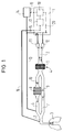
- the arrangement comprises a common line 2 for the supply and delivery of anesthetic and respiratory gases to and from a patient 3.
- a common line 2 for the supply and delivery of anesthetic and respiratory gases to and from a patient 3.
- an adsorption filter 4 which contains an adsorbent material 5 for the adsorption and desorption of anesthetic gases.
- the line between the patient 3 and the adsorption filter 4 is partially divided into an inhalation branch 6 and an exhalation branch 7, an absorber for carbon dioxide being arranged in the inhalation branch 6.
- a one-way valve 9 or 10 is arranged in each of the inhalation and exhalation branches 6, 7.
- the one-way valve 10 of the inhalation branch 6 is attached between the adsorption filter 4 and the absorber 8.
- the free end of the common line 2 forms a Y-shaped termination, one branch 11 of which is connected via a respirator 1 to an evacuation system (not shown) for the expiratory gas and the other branch 12 to the ventilator 1 for the supply of respiratory gas.
- a line 13 for the supply of anesthetic gases from an anesthetic gasifier 14 is connected to the inhalation branch 6 between the absorber 8 and the patient 3.
- the anesthetic gasifier 14 can also be fitted in the ventilator 1.
- a line 15 is connected to line 13, which line is connected to the ventilator 1, via this Lines 15 and 13 can supply 3 fresh breathing gas to the patient if necessary.
- a gas line 16 is connected to the line 2 and carries a sample of the gas mixture which is supplied to the patient 3 to a device 17 for measuring the gas concentration directs.
- a sensor signal corresponding to the gas concentration of the gas mixture is then fed to a control device 18, which controls the supply of anesthetic or respiratory gases in a feedback-controlled manner such that the desired gas concentration is fed to the patient 3.
- the dash-dotted lines 19, 20 represent connections between the control device 18 and the anesthetic gasifier 14 or between the control device 18 and the line 15 and the branch 12 for delivering respiratory gases. Both the measuring and the control device 17, 18 are in this Embodiment arranged in the ventilator 1.
- the exhalation gas from patient 3 passes through the exhalation branch 7, the one-way valve 9 and the adsorption filter 4.
- the anesthetic gas supplied in an earlier inhalation phase which the patient 3 has not absorbed, as well as moisture from the exhalation gas and a smaller part of carbon dioxide now become adsorbed in the adsorption filter 4, while the rest of the exhaled gas passes through the line 2 and the branch 11 via the ventilator 1 into the evacuation system.
- fresh breathing gas from the ventilator 1 passes through the branch 12, the line 2 and the adsorption filter 4, the adsorbed anesthetic gas and the moisture and the adsorbed carbon dioxide being desorbed and mixed with the fresh breathing gas.
- this gas mixture is passed over the inhalation branch 6, the one-way valve 10 and over the absorber 8, which absorbs the residues of carbon dioxide in the gas mixture.
- a sample of this mixture is taken, which, as already described, is led via the gas line 16 to the measuring device 17 in the ventilator 1.
- the measurement signals are fed to the control device 18 which, depending on this, emits signals to the anesthetic gasifier 14 and the respirator 1 so that the correct quantities and the desired mixture of anesthetic and respiratory gases are fed to the patient.
- These gases are fed to the gas mixture through line 13 before they reach patient 3.
- the supply of breathing gas from the ventilator 1 via the common line 2 and the inhalation branch 6 is blocked.
- the anesthetic gasifier 14 is also switched off, as a result of which only fresh breathing gas is supplied from the ventilator 1 to the patient 3 via the lines 15 and 13.
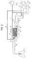
- FIG. 2 shows that the adsorption filter 4 and the absorber 8 are arranged in parallel and at a distance from one another in a container 21 in such a way that channels are formed.
- a first channel 22 is formed between the adsorption filter 4 and the absorber 8, a second channel 23 between the adsorption filter 4 and a first inner wall 24 and a third channel 25 between the absorber 8 and a second inner wall 26 of the container 21.
- One side of the channels 22, 23, 25 is open and the other sides of the channels are closed.
- the channel 22 is connected to the exhalation branch 7, the channel 23 on the side of the container 21 facing away from the patient 3 to the common line 2 and the channel 25 to the inhalation branch 6.
- a Germ filter 27 arranged following the adsorption filter 4 on the side facing away from the patient 3 .
- the germ filter 27 is intended to prevent germs from the exhaled gas from contaminating the hoses and the container, so that they do not have to be cleaned after the treatment.
- an anesthetic gasifier 14 is connected to the arrangement in the described embodiment, which is connected via line 13, for example, to the closed end of the channel 25 for the supply of fresh anesthetic gas.
- a measuring device 17 which measures the gas concentration of the inhalation gas
- a control device 18 which, as already described, controls the volume of the respiratory or anesthetic gases which are supplied to the patient 3.
- the exhalation gas flows through a short flexible hose 28, via the common line 2 and through the one-way valve 9 in the exhalation branch 7.
- the exhalation gas continues to flow through the channel 22 and then passes through the adsorption filter 4.
- Anesthetic gas and moisture from the previous inhalation phase, which the patient 3 has not absorbed and a smaller amount of carbon dioxide are adsorbed in the adsorption filter 4, while the rest of the exhaled gas is transported out through the line 2, the branch 11 and via the ventilator 1 into the evacuation system.
- fresh breathing gas is passed from the ventilator 1, the branch 12, the line 2, the germ filter 27 and the adsorption filter 4.
- the adsorbed anesthetic gas and the moisture as well as the adsorbed carbon dioxide are desorbed and, together with the respiratory gas, caused to pass through the channel 22 and then through the absorber 8, in which the carbon dioxide residues are collected, and then through the channel 25, the one-way valve 10, which Line 2 and hose 28 to flow to patient 3.
- the arrangement of the lines can be short, which reduces the unavoidable "dead space”.
- the inhalation and exhalation branches 6, 7 can be lengthened by means of patient tubes 31, 32. These patient tubes 31, 32 are connected to the end of the common line 2, as shown in FIG. 3. In this way, the arrangement is just as effective as it would be connected directly to patient 3, and the "dead space" can be kept as small as that described in connection with FIG.
- coal in particular coconut shell charcoal or charcoal
- the coal also adsorbs a lot of moisture from the exhalation gas, which is desorbed during the inhalation phase and mixed with the rest of the inhalation gas. This gives a very good moisture-heat exchanger.
- the container shown in FIGS. 2 and 3, which contains the adsorption material 5 and the adsorber 8, is inexpensive to manufacture due to its small size and simplicity and is therefore suitable as a disposable product. After treatment, the container 21 is disconnected from the patient tubes and the lines and replaced with a new container.
Landscapes
- Health & Medical Sciences (AREA)
- Anesthesiology (AREA)
- Life Sciences & Earth Sciences (AREA)
- Engineering & Computer Science (AREA)
- Public Health (AREA)
- Animal Behavior & Ethology (AREA)
- Veterinary Medicine (AREA)
- General Health & Medical Sciences (AREA)
- Emergency Medicine (AREA)
- Pulmonology (AREA)
- Biomedical Technology (AREA)
- Heart & Thoracic Surgery (AREA)
- Hematology (AREA)
- Ecology (AREA)
- Environmental Sciences (AREA)
- Biodiversity & Conservation Biology (AREA)
- Environmental & Geological Engineering (AREA)
- Measurement Of The Respiration, Hearing Ability, Form, And Blood Characteristics Of Living Organisms (AREA)
- Pharmaceuticals Containing Other Organic And Inorganic Compounds (AREA)
- Acyclic And Carbocyclic Compounds In Medicinal Compositions (AREA)
- Medicinal Preparation (AREA)
- Medicines That Contain Protein Lipid Enzymes And Other Medicines (AREA)
- Respiratory Apparatuses And Protective Means (AREA)
Description
- Die Erfindung bezieht sich auf ein Verfahren zur Wiederverwendung von Anästhesiegasen bei der Inhalationsanästhesie und Anordnung zur Durchführung des Verfahrens.
- Durch die SE-AS 459 155 ist bekannt, daß frisches Gas mit Anästhesiemittel aus einem Anästhesiemittelvergaser in der zum Patienten ein- und ausgehenden Sammelleitung gemischt wird und daß bei der Ausatmung des Patienten das Ausatmungsgas ein Adsorptionsfilter passiert. Dasjenige Anästhesiemittel, das vom Patienten nicht absorbiert wird, wird vom Adsorptionsmaterial im Adsorptionsfilter adsorbiert, während der größte Teil des Ausatmungsgases das Filter passiert. Bei der Einatmung des Patienten wird das adsorbierte Anästhesiemittel aus dem Adsorptionsmaterial desorbiert und dem Patienten wieder zugeführt. Es kann jedoch nicht vermieden werden, daß bei solchen Adsorbtionsfiltern eine geringe Menge Kohlendioxyd aus dem Ausatmungsgas des Patienten im Adsorptionsmaterial adsorbiert, danach desorbiert und während der Einatmungsphase dem Patienten wieder zugeführt wird.
- Der Erfindung liegt die Aufgabe zugrunde, ein verfahren und eine Anordnung zur Durchführung des Verfahrens der eingangs genannten Art zu schaffen, wodurch mit einfachen Mitteln verhindert wird, daß das aus dem Ausatmungsgas des Patienten im Adsorptionsmaterial adsorbierte Kohlendioxyd bei der nächsten Einatmungsphase dem Patienten zugeführt wird.
- Diese Aufgabe ist durch die Merkmale des Anspruchs 1 gelöst. Dadurch, daß wenigstens das Gas, das das Adsorptionsfilter passiert hat, einen Absorber für Kohlendioxyd passiert, bevor es dem Patienten zugeführt wird, ist die Gasmischung frei von Kohlendioxyd, wenn sie den Patienten erreicht. Der Absorber kann verhältnismäßig klein gemacht werden, da er in der Einatmungsphase lediglich eine geringe Menge Kohlendioxyd aufzunehmen braucht.
- Es ist nicht sinnvoll, einen Kohlendioxydabsorber in der gemeinsamen Leitung zwischen dem Adsorptionsfilter und dem Patienten in der Anordnung anzubringen, wie es in der SE-AS 459 155 beschrieben ist. Ein solcher Absorber müßte sehr groß sein um das gesamte Kohlendioxyd aus dem Ausatmungsgas des Patienten zu absorbieren. Der Absorber würde auch aufgrund seiner Größe einen unannehmbar großen Ausatmungswiderstand bilden.
- In einer Weiterbildung des Verfahrens wird vorgeschlagen, daß die Gaskonzentration einer gewünschten Gassorte zwischen dem Patienten und dem Absorber gemessen und zur Steuerung des frischen Atmungs- bzw. Anästhesiegases das der Gasmischung zugeführt wird, benutzt wird. Hierdurch wird erreicht, daß der Patient immer eine gewünschte Gaskonzentration erhält.
- In einer vorteilhaften Ausbildung des Verfahrens wird vorgeschlagen, daß die Steuerung Feedback-kontrolliert erfolgt, wobei die gemessene Gaskonzentration den Istwert bildet und die gewünschte Gaskonzentration den Sollwert bestimmt. Durch die erwähnte Steuerung erfolgt automatisch eine Regelung der Gaskonzentration, die dem Patienten zugeführt wird.
- Nach der Erfindung wird auch eine Anordnung zur Durchführung des Verfahrens geschaffen, die eine gemeinsame Leitung für die Zufuhr und Abgabe von Anästhesie- und Atmungsgasen zu bzw. von einem Patienten umfaßt, wobei in dieser Leitung ein Adsorptionsfilter angeordnet ist, das ein Adsorptionsmaterial für die Adsorption und Desorption von Anästhesiegasen beinhaltet, und die eine zweite Leitung für die Zufuhr von Anästhesie- und/oder Atmungsgasen zum Patienten vorbei an dem Adsorptionsfilter umfaßt. Das Wesentliche dieser Anordnung ist, daß die gemeinsame Leitung zwischen dem Patienten und dem Adsorptionsfilter mindestens teilweise in einen Ein- bzw. Ausatmungszweig aufgeteilt ist, wobei in dem Einatmungszweig ein Absorber für Kohlendioxyd angeordnet ist. Durch diesen Absorber, der die Kohlendioxydreste absorbiert, wird dem Patienten in der Einatmungsphase kein Kohlendioxyd zugeführt.
- In einer weiteren vorteilhaften Ausbildung der Erfindung wird vorgeschlagen, daß als Adsorptionsmaterial Kohle verwendet wird. Kohle ist ein sehr gutes Adsorptionsmaterial für Anästhesiemittel wie z.B. Halothan. Kohle ist auch ein sehr guter Feuchtigkeitsadsorber und stellt hierdurch einen guten Feuchtigkeit-Wärme-Wechsler dar. Wegen der hohen Adsorptionsfähigkeit der Kohle kann das Adsorptionsfilter verhältnismäßig klein gemacht werden.
- Im Hinblick auf eine günstige konstruktive Ausgestaltung der Erfindung wird vorgeschlagen, daß das Adsorptionsfilter und der Absorber hauptsächlich paralell und mit Abstand zueinander derart in einem Behälter angebracht sind, daß ein erster Kanal zwischen dem Adsorptionsfilter und dem Absorber gebildet ist, daß ein zweiter Kanal zwischen dem Adsorptionsfilter und einer ersten Innenwand des Behälters gebildet ist und daß ein dritter Kanal zwischen dem Absorber und einer zweiten Innenwand des Behälters gebildet ist, daß der erste Kanal an dem Ausatmungszweig, der zweite Kanal an der dem Patienten abgewandten Seite des Adsorptionsfilters an der gemeinsamen Leitung und der dritte Kanal an dem Einatmungszweig angeschlossen ist. Hierdurch wird ein kleines, einfaches, billiges und kompaktes Teil erhalten, das sowohl das Adsorptionsfilter als auch den Absorber beinhaltet. Dieses Teil kann daher als Wegwerfprodukt verwendet werden.
- Eine günstige Ausgestaltung der Erfindung wird dadurch erhalten, daß im Anschluß an das Adsorptionsfilter an der dem Patienten abgewandten Seite ein Keimfilter angeordnet ist. Hierdurch wird erreicht, daß Keime aus dem Ausatmungsgas herausgefiltert werden. Auf dieser Weise wird verhindert, daß Leitungen und Beatmungsgerät kontaminiert werden. Diese brauchen daher nach einer Behandlung nicht gesäubert zu werden.
- Eine weitere günstige Ausgestaltung der Erfindung wird erhalten, indem an der gemeinsamen Leitung bzw. an dem Einatmungszweig zwischen dem Patienten und dem Absorber eine Gasleitung angeschlossen ist, die einen Teil der Gasmischung, die dem Patienten zugeführt wird, zu einer Vorrichtung zur Messung einer Gaskonzentration mindestens einer Gassorte führt, und wobei ein der Gaskonzentration entsprechendes Sensorsignal einer Steuervorrichtung zugeführt wird, die Feedback-kontrolliert die Zufuhr von Anästhesie- bzw. Atmungsgasen zur Gasmischung über eine Leitung derart steuert, daß dem Patienten eine gewünschte Gaskonzentration dem Patienten zugeführt wird. Auf diese Weise wird immer automatisch eine Regelung der gewünschten Gaskonzentration erzielt, die dem Patienten zugeführt wird.
- Weitere Vorteile und Einzelheiten ergeben sich aus den Unteransprüchen.
- Die Erfindung ist nachfolgend anhand eines in den Zeichnungen dargestellten Ausführungsbeispiels näher erläutert.
- Es zeigen:
- FIG 1
- eine Ausführungsform der Anordnung nach der Erfindung, bei der die Anordnung an ein Beatmungsgerät angeschlossen ist und
- FIG 2 und 3
- weitere Ausführungsformen der Anordnung nach der Erfindung.
- In der FIG 1 ist eine Anordnung zur Wiederverwendung von Anästhesiegasen bei der Inhalationsanästhesie gezeigt, die an ein Beatmungsgerät 1 angeschlossen ist. Die Anordnung umfaßt eine gemeinsame Leitung 2 für die Zufuhr und Abgabe von Anästhesie- und Atmungsgasen zu bzw. von einem Patienten 3. In der gemeinsamen Leitung 2 ist ein Adsorptionsfilter 4 angeordnet, das ein Adsorptionsmaterial 5 für die Adsorption und Desorption von Anästhesiegasen beinhaltet. Die Leitung zwischen dem Patienten 3 und dem Adsortionsfilter 4 ist teilweise in einen Einatmungszweig 6 und in einen Ausatmungszweig 7 aufgeteilt, wobei in dem Einatmungszweig 6 ein Absorber für Kohlendioxyd angeordnet ist. In dem Ein-und Ausatmungszweig 6,7 ist jeweils ein Einwegeventil 9 bzw. 10 angeordnet. Das Einwegeventil 10 des Einatmungszweiges 6 ist zwischen dem Adsorbtionsfilter 4 und dem Absorber 8 angebracht. Das freie Ende der gemeinsamen Leitung 2 bildet einen Y-förmigen Abschluß, dessen einen Zweig 11 über ein Beatmungsgerät 1 mit einem nicht gezeigten Evakuierungssystem für das Ausatmungsgas und dessen anderen Zweig 12 mit dem Beatmungsgerät 1 für die Zufuhr von Atmungsgas verbunden ist. An dem Einatmungszweig 6 zwischen dem Absorber 8 und dem Patienten 3 ist eine Leitung 13 für die Zufuhr von Anästhesiegasen aus einem Narkosemittelvergaser 14 angeschlossen. Der Narkosemittelvergaser 14 kann auch im Beatmungsgerät 1 angebracht sein. An der Leitung 13 ist eine Leitung 15 angeschlossen, die mit dem Beatmungsgerät 1 verbunden ist, das über diese Leitungen 15 und 13 bei Bedarf dem Patienten 3 frisches Atmungsgas zuführen kann.
- Zwischen der Leitung 13 für die Zufuhr von Anästhesiegasen bzw. frischen Atemgasen und dem Patienten 3 ist an der Leitung 2 eine Gasleitung 16 angeschlossen, die eine Probe von der Gasmischung, die dem Patienten 3 zugeführt wird, an eine Vorrichtung 17 für die Messung der Gaskonzentration leitet. Ein Sensorsignal entsprechend der Gaskonzentration der Gasmischung wird danach einer Steuervorrichtung 18 zugeführt, die Feedback-kontrolliert die Zufuhr von Anästhesie- bzw. Atmungsgasen derart steuert, daß die gewünschte Gaskonzentration dem Patienten 3 zugeführt wird. Die strichpunktierte Linien 19,20 stellen Verbindungen zwischen der Steuervorrichtung 18 und dem Narkosemittelvergaser 14 bzw. zwischen der Steuervorrichtung 18 und der Leitung 15 und dem Zweig 12 zur Abgabe von Atmungsgasen dar. Sowohl die Meß- als auch die Steuervorrichtung 17,18 sind in diesem Ausführungsbeispiel im Beatmungsgerät 1 angeordnet.
- In einer Ausatmungsphase passiert das Ausatmungsgas vom Patienten 3 den Ausatmungszweig 7, das Einwegeventil 9 und das Adsorptionsfilter 4. Das in einer früheren Einatmungsphase zugeführte Anästhesiegas, das der Patient 3 nicht absorbiert hat, sowie Feuchtigkeit aus dem Ausatmungsgas und ein geringerer Teil von Kohlendioxyd werden nun im Adsorptionsfilter 4 adsorbiert, während der Rest des Ausatmungsgases die Leitung 2 und den Zweig 11 passiert über das Beatmungsgerät 1 in das Evakuierungssystem gelangt. In der Einatmungsphase passiert frisches Atmungsgas vom Beatmungsgerät 1 den Zweig 12, die Leitung 2 und das Adsorptionsfilter 4 wobei das adsorbierte Anästhesiegas sowie die Feuchtigkeit und das adsorbierte Kohlendioxyd desorbiert werden und sich mit dem frischen Atmungsgas mischen. Da das Einwegeventil 9 in dem Ausatmungszweig 7 in der Einatmungsphase sperrt, wird diese Gasmischung über den Einatmungszweig 6, das Einwegeventil 10 und über den Absorber 8, der die Reste des Kohlendioxyds in der Gasmischung absorbiert, geleitet. Bevor die Gasmischung den Patienten 3 erreicht, wird eine Probe dieser Mischung entnommen, die, wie bereits beschrieben, über die Gasleitung 16 zur Meßvorrichtung 17 im Beatmungsgerät 1 geführt wird. Die Meßsignale werden der Steuervorrichtung 18 zugeführt, die in Abhängigkeit davon Signale an den Narkosevergaser 14 und das Beatmungsgerät 1 abgibt, damit die richtigen Mengen und die gewünschte Mischung von Anästhesie- und Atmungsgasen dem Patienten zugeführt werden. Durch die Leitung 13 werden diese Gase der Gasmischung zugeführt, bevor sie den Patienten 3 erreichen. In der Aufwachphase des Patienten 3 wird die Zufuhr von Atmungsgas vom Beatmungsgerät 1 über die gemeinsame Leitung 2 und den Einatmungszweig 6 gesperrt. Auch der Narkosevergaser 14 wird ausgeschaltet, wodurch lediglich frisches Atmungsgas vom Beatmungsgerät 1 dem Patienten 3 über die Leitungen 15 und 13 zugeführt wird.
- In der FIG 2 ist dargestellt, daß das Adsorptionsfilter 4 und der Absorber 8 parallel und mit Abstand zueinander in einem Behälter 21 derart angebracht sind, daß Kanäle gebildet werden. Ein erster Kanal 22 wird zwischen dem Adsorptionsfilter 4 und dem Absorber 8, ein zweiter Kanal 23 zwischen dem Adsorptionsfilter 4 und einer ersten Innenwand 24 und ein dritter Kanal 25 zwischen dem Absorber 8 und einer zweiten Innenwand 26 des Behälters 21 gebildet. Die eine Seite der Kanäle 22,23,25 ist offen und die anderen Seiten der Kanäle sind geschlossen. Der Kanal 22 ist an dem Ausatmungszweig 7, der Kanal 23 an der dem Patienten 3 abgewandten Seite des Behälters 21 an der gemeinsamen Leitung 2 und der Kanal 25 an dem Einatmungszweig 6 angeschlossen. Im Anschluß an das Adsorptionsfilter 4 an der dem Patienten 3 abgewandten Seite ist ein Keimfilter 27 angeordnet. Das Keimfilter 27 soll verhindern, daß Keime aus dem Ausatmungsgas die Schläuche und den Behälter kontaminieren, so daß sie nach der Behandlung nicht gereinigt werden müssen. An der Anordnung in der beschriebenen Ausführungsform ist wie im vorher beschriebenen Beispiel ein Narkosemittelvergaser 14 angeschlossen, der über die Leitung 13 z.B. an das geschlossene Ende des Kanals 25 für die Zufuhr von frischem Anästhesiegas angeschlossen ist. Es gibt außerdem eine Meßvorrichtung 17 die die Gaskonzentration des Einatmungsgases mißt und eine Steuervorrichtung 18 die wie bereits beschrieben das Volumen der Atmungs- bzw. Anästhesiegasen, die den Patienten 3 zugeführt werden, steuert.
- In der Ausatmungsphase strömt das Ausatmungsgas durch einen kurzen flexiblen Schlauch 28, über die gemeinsame Leitung 2 und durch das Einwegeventil 9 im Ausatmungszweig 7. Das Ausatmungsgas strömt weiterhin durch den Kanal 22 und passiert danach das Adsorptionsfilter 4. Anästhesiegas und Feuchtigkeit aus der vorhergehenden Einatmungsphase, die der Patient 3 nicht absorbiert hat, sowie eine geringere Menge Kohlendioxyd werden in dem Adsorptionsfilter 4 adsorbiert, während der Rest des Ausatmungsgases durch die Leitung 2, den Zweig 11 und über das Beatmungsgerät 1 in das Evakuierungssystem heraustransportiert wird. In der Einatmungsphase wird frisches Atmungsgas vom Beatmungsgerät 1, den Zweig 12, die Leitung 2, den Keimfilter 27 und das Adsorptionsfilter 4 geleitet. Das adsorbierte Anästhesiegas und die Feuchtigkeit sowie das adsorbierte Kohlendioxyd werden desorbiert und zusammen mit dem Beatmungsgas dazu gebracht, den Kanal 22 und danach den Absorber 8 zu passieren, in dem die Kohlendioxydreste aufgefangen werden, um danach durch den Kanal 25, das Einwegeventil 10, die Leitung 2 und den Schlauch 28 zum Patient 3 zu strömen. Durch die beschriebene Ausführungsform der Anordnung können die Leitungen kurz sein, was den nicht zu vermeidenden "dead space" verkleinert.
- Wenn der Narkosearzt aus irgend einem Grund die Anordnung nicht in der Nähe des Patienten anbringen will, können die Ein- und Ausatmungszweige 6,7 mittels Patientenschläuche 31,32 verlängert werden. Diese Patientenschläuche 31,32 werden am Ende der gemeinsamen Leitung 2 angeschlossen, wie es in der FIG 3 dargestellt ist. Auf diese Weise wird die Anordnung genau so wirkungsvoll wie sie direkt am Patient 3 angeschlossen wäre wobei der "dead space" genau so klein gehalten werden kann wie der, der in Verbindung mit FIG 2 beschrieben wird.
- Es hat sich gezeigt, daß als Adsorptionsmaterial 5 für das Adsorptionsfilter Kohle, insbesondere Kokosnußschalenkohle oder Holzkohle sehr geeignet ist. Die Kohle adsorbiert auch viel Feuchtigkeit aus dem Ausatmungsgas, das in der Einatmungsphase desorbiert und mit dem übrigen Einatmungsgas gemischt wird. Hierdurch ist eine sehr guter Feuchtigkeit-Wärmewechsler gegeben.
- Der in den FIG 2 und 3 gezeigten Behälter, der das Adsorptionsmateral 5 und den Adsorber 8 enthält, ist aufgrund seiner geringen Größe und seiner Einfachheit in der Herstellung billig und ist daher als Wegwerfprodukt geeignet. Nach einer Behandlung wird der Behälter 21 von den Patientenschläuchen und den Leitungen getrennt und durch einen neuen Behälter ersetzt.
-
- 1
- Beatmungsgerät
- 2
- Leitung
- 3
- Patient
- 4
- Adsorptionsfilter
- 5
- Adsorptionsmaterial
- 6
- Einatmungszweig
- 7
- Ausatmungszweig
- 8
- Absorber
- 9,10
- Einwegeventil
- 11,12
- Zweig
- 13,15
- Leitung
- 14
- Narkosemittelvergaser
- 16
- Gasleitung
- 17
- Vorrichtung, Meßvorrichtung
- 18
- Steuervorrichtung
- 19,20
- strichpunktierte Linie
- 21
- Behälter
- 22,23,25
- Kanal
- 24,26
- Innenwand
- 27
- Keimfilter
- 28
- Flexibler Schlauch
- 31,32
- Patientenschlauch
Claims (12)
- Verfahren zur Wiederverwendung von Anästhesiegasen bei der Inhalationsanästhesie, bei dem ein Patient (3) mittels Anästhesie- und/oder Beatmungsgas beatmet wird, wobei das Ausatmungsgas des Patienten (3) ein Adsorptionsfilter (4) für Anästhesiegas durchströmt und das nicht vom Patienten (3) absorbierte Anästhesiegas von einem im Adsorptionsfilter (4) vorhanden Adsorptionsmaterial (5) adsorbiert wird, während das restliche Ausatmungsgas dieses Filter (4) passiert und wobei bei einer Einatmung frisches Atmungsgas durch das Adsorptionsfilter (4) strömt, wobei das adsorbierte Anästhesiegas desorbiert und mit dem neuen Atmungsgas eine Gasmischung bildet, die dem Patienten (3) zugeführt wird, und wobei frisches Atmungsgas und/oder frisches Anästhesiegas, das das Adsorptionsfilter (4) nicht passiert, der Gasmischung direkt zugeführt werden kann, um die gewünschte Gaskonzentration aufrechtzuerhalten, dadurch gekennzeichnet, daß wenigstens das Gas, das das Adsorptionsfilter (4) durchsströmt, einen Absorber (8) für Kohlendioxyd passiert, bevor es dem Patienten (3) zugeführt wird.
- Verfahren nach Anspruch 1, dadurch gekennzeichnet, daß die Gaskonzentration einer gewünschten Gassorte zwischen dem Patienten (3) und dem Absorber (8) gemessen und zur Steuerung des frischen Atmungs- bzw. Anästhesiegases, das der Gasmischung zugeführt wird, benutzt wird.
- Verfahren nach Anspruch 2, dadurch gekennzeichnet, daß die Steuerung Feedback-kontrolliert erfolgt, wobei die gemessene Gaskonzentration den Istwert bildet und die gewünschte Gaskonzentration den Sollwert bestimmt.
- Verfahren nach einem der Ansprüche 1 bis 3, dadurch gekennzeichnet, daß als Adsorptionsmaterial (5) Kohle verwendet wird.
- Anordnung zur Durchführung des Verfahrens zur Wiederverwendung von Anästhesiegasen bei der Inhalationsanästhesie nach einem der Ansprüche 1 bis 4, die eine gemeinsame Leitung (2) für die Zufuhr und Abgabe von Anästhesie- und Atmungsgasen zu bzw. von einem Patienten (3) umfaßt, wobei in dieser Leitung (2) ein Adsorptionsfilter (4) angeordnet ist, das ein Adsorptionsmaterial (5) für die Adsorption und Desorption von Anästhesiegasen beinhaltet, und die eine zweite Leitung (13,15) für die Zufuhr von Anästhesie- und/oder Atmungsgasen zum Patienten (3) vorbei an dem Adsorptionsfilter (4) umfaßt, dadurch gekennzeichnet, daß die gemeinsame Leitung (2) zwischen dem Patienten (3) und dem Adsorptionsfilter (4) mindestens teilweise in einen Ein- bzw. Ausatmungszweig (6,7) aufgeteit ist, wobei in dem Einatmungszweig (6) ein Absorber (8) für Kohlendioxyd angeordnet ist.
- Anordnung nach Anspruch 5, dadurch gekennzeichnet, daß als Adsorptionsmaterial (5) Kohle verwendet wird.
- Anordnung nach Anspruch 6, dadurch gekennzeichnet, daß als Adsorptionsmaterial (5) Kokosnußschalenkohle verwendet wird.
- Anordnung nach Anspruch 6, dadurch gekennzeichnet, daß als Adsorptionsmaterial (5) Holzkohle verwendet wird.
- Anordnung nach einem der Ansprüche 5 bis 8, dadurch gekennzeichnet, daß das Adsorptionsfilter (4) und der Absorber (8) hauptsächlich paralell und mit Abstand zueinander derart in einem Behälter (21) angebracht sind, daß ein erster Kanal (22) zwischen dem Adsorptionsfilter (4) und dem Absorber (8) gebildet ist, daß ein zweiter Kanal (23) zwischen dem Adsorptionsfilter (4) und einer ersten Innenwand (24) des Behälters (21) gebildet ist und daß ein dritter Kanal (25) zwischen dem Absorber (8) und einer zweiten Innenwand (26) des Behälters (21) gebildet ist, daß der erste Kanal (22) an dem Ausatmungszweig (7) der zweite Kanal (23) an der dem Patienten (3) abgewandten Seite des Adsorptionsfilters (4) an der gemeinsamen Leitung (2) und der dritte Kanal (25) an dem Einatmungszweig (6) angeschlossen ist.
- Anordnung nach einem der Ansprüche 5 bis 9, dadurch gekennzeichnet, daß im Anschluß an das Adsorptionsfilter (4) an der dem Patienten (3) abgewandten Seite ein Keimfilter (27) angeordnet ist.
- Anordnung nach einem der Ansprüche 5 bis 10, dadurch gekennzeichnet, daß an der gemeinsamen Leitung (2) bzw. an dem Einatmungszweig (6) zwischen dem Patienten (3) und dem Absorber (8) eine Gasleitung (16) angeschlossen ist, die einen Teil der Gasmischung, die dem Patienten (3) zugeführt wird, zu einer Vorrichtung (17) zur Messung einer Gaskonzentration mindestens einer Gassorte führt, und wobei ein der Gaskonzentration entsprechendes Sensorsignal einer Steuervorrichtung (18) zugeführt wird, die Feedback-kontrolliert die Zufuhr von Anästhesie- bzw. Atmungsgasen zur Gasmischung über eine Leitung (13) derart steuert, daß dem Patienten (3) eine gewünschte Gaskonzentration zugführt wird.
- Anordnung nach Anspruch 11, dadurch gekennzeichnet, daß die Meß- und Steuervorrichtungen in einem Beatmungsgerät angebracht sind.
Applications Claiming Priority (2)
| Application Number | Priority Date | Filing Date | Title |
|---|---|---|---|
| SE9001581A SE9001581D0 (sv) | 1990-05-03 | 1990-05-03 | Foerfarande foer aateranvaendning av anestesigas och anordning foer genomfoerande av foerfarandet |
| SE9001581 | 1990-05-03 |
Publications (2)
| Publication Number | Publication Date |
|---|---|
| EP0455049A1 EP0455049A1 (de) | 1991-11-06 |
| EP0455049B1 true EP0455049B1 (de) | 1995-01-04 |
Family
ID=20379364
Family Applications (1)
| Application Number | Title | Priority Date | Filing Date |
|---|---|---|---|
| EP91106158A Expired - Lifetime EP0455049B1 (de) | 1990-05-03 | 1991-04-17 | Verfahren zur Wiederverwendung von Anästhesiegasen bei der Inhalationsanästhesie und Anordnung zur Durchführung des Verfahrens |
Country Status (7)
| Country | Link |
|---|---|
| US (1) | US5471979A (de) |
| EP (1) | EP0455049B1 (de) |
| JP (1) | JP3249146B2 (de) |
| AT (1) | ATE116560T1 (de) |
| DE (1) | DE59104116D1 (de) |
| ES (1) | ES2067079T3 (de) |
| SE (1) | SE9001581D0 (de) |
Families Citing this family (63)
| Publication number | Priority date | Publication date | Assignee | Title |
|---|---|---|---|---|
| US5611332A (en) * | 1995-03-22 | 1997-03-18 | Bono; Michael | Aerosol inhalation device containing a rain-off chamber |
| SE505217C2 (sv) * | 1995-10-16 | 1997-07-14 | Gibeck Ab Louis | Anordning för återvinning av anestesimedel |
| SE9503665L (sv) * | 1995-10-19 | 1997-04-20 | Siemens Elema Ab | Narkossystem |
| US5829428A (en) * | 1996-05-29 | 1998-11-03 | Alliance Pharmaceutical Corp. | Methods and apparatus for reducing the loss of respiratory promoters |
| US6123072A (en) * | 1996-09-11 | 2000-09-26 | Downs; John B. | Method and apparatus for breathing during anesthesia |
| US5673688A (en) * | 1996-09-26 | 1997-10-07 | Ohmeda Inc. | Anesthesia system with CO2 monitor to suppress CO2 breakthrough |
| SE509580C2 (sv) * | 1996-11-18 | 1999-02-08 | Gibeck Ab Louis | Regenererbar absorbatoranordningsapparat, jämte ett förfarande för avlägsnande av koldioxid från utandningsgaser under anestesi samt ett recirkulerande recirkulerande system för anestesi. |
| US5803064A (en) * | 1997-08-12 | 1998-09-08 | University Technology Corporation | Anesthesia system for use with magnetic resonance imaging systems |
| US6206002B1 (en) * | 1997-11-06 | 2001-03-27 | Hudson Rci Ab | Device and method for recovering anaesthetic during the use of inhaled anaesthetics |
| US6263874B1 (en) | 1997-11-18 | 2001-07-24 | Ledez Kenneth Michael | Combined anesthetic and scavenger mask |
| NL1007699C2 (nl) * | 1997-12-04 | 1999-06-09 | Medisize Bv | Beademingssysteem. |
| US5992413A (en) * | 1997-12-24 | 1999-11-30 | Enternet Medical, Inc. | Heat and moisture exchanger and generator |
| GB2335604A (en) * | 1998-03-26 | 1999-09-29 | Eugenio Brugna | Anaesthesia apparatus |
| SE9802568D0 (sv) * | 1998-07-17 | 1998-07-17 | Siemens Elema Ab | Anaesthetic delivery system |
| US6634355B2 (en) * | 1999-06-11 | 2003-10-21 | Colas Marie-Jose | Single breath induction anesthesia apparatus |
| US7007693B2 (en) * | 1999-08-03 | 2006-03-07 | The Research Foundatilon Of State University Of New York | Device and method of reducing bias flow in oscillatory ventilators |
| US6588421B1 (en) * | 2000-09-29 | 2003-07-08 | Dhd Healthcare Corporation | HME bypass system |
| SE0100064D0 (sv) | 2001-01-10 | 2001-01-10 | Siemens Elema Ab | Anaesthetic filter arrangement |
| US20020148471A1 (en) * | 2001-03-09 | 2002-10-17 | Go Hirabayashi | Radiative artificial respiration system with carbon dioxide absorbent and canister for use in same |
| SE0201212D0 (sv) * | 2002-04-23 | 2002-04-23 | Siemens Elema Ab | Anaesthetic Delivery System |
| SE0201213D0 (sv) | 2002-04-23 | 2002-04-23 | Siemens Elema Ab | Anaesthetic Filter Arrangement |
| SE0203518D0 (sv) * | 2002-11-28 | 2002-11-28 | Siemens Elema Ab | Slang avsedd att användas i ett narkossystem |
| SE0300161D0 (sv) * | 2003-01-23 | 2003-01-23 | Siemens Elema Ab | Anesthetic Reflector |
| US7353825B2 (en) * | 2003-05-01 | 2008-04-08 | Axon Medical, Inc. | Apparatus and techniques for reducing the effects of general anesthetics |
| US7621272B2 (en) * | 2003-05-01 | 2009-11-24 | Anecare Laboratories, Inc. | Apparatus and techniques for reducing the effects of general anesthetics |
| SE526141C2 (sv) * | 2003-10-20 | 2005-07-12 | Hudson Rci Ab | Anordning och förfarande för återvinning av anestesimedel |
| US20060078506A1 (en) * | 2004-05-20 | 2006-04-13 | Ralph Niven | Methods, systems and devices for noninvasive pulmonary delivery |
| SE528481C2 (sv) * | 2004-07-19 | 2006-11-21 | Hudson Rci Ab | Anordning för återanvändning av anestesimedel vid användning av inhalerade anestesimedel |
| AU2005280281A1 (en) * | 2004-08-27 | 2006-03-09 | Discovery Laboratories, Inc. | Methods, systems and devices for noninvasive pulmonary delivery |
| SE0402572D0 (sv) * | 2004-10-25 | 2004-10-25 | Hans Lambert | Improvement of a device for recovering anaesthetic |
| US8028697B2 (en) | 2005-04-28 | 2011-10-04 | Trudell Medical International | Ventilator circuit and method for the use thereof |
| US8459262B2 (en) * | 2005-12-21 | 2013-06-11 | Maquet Critical Care Ab | Manual ventilation with electronically controlled APL valve |
| US7832398B2 (en) * | 2005-12-29 | 2010-11-16 | General Elecrtic Company | Arrangement in connection with an anaesthesia/ventilation system for a patient and a gas separation unit for an anaesthesia/ventilation system |
| WO2007110112A1 (en) * | 2006-03-29 | 2007-10-04 | Maquet Critical Care Ab | Filter arrangement |
| US8127762B2 (en) * | 2006-06-29 | 2012-03-06 | Maquet Critical Care Ab | Anaesthesia apparatus and method for operating an anaesthesia apparatus |
| EP2008679A1 (de) * | 2007-06-28 | 2008-12-31 | General Electric Company | Patientenbeatmungssystem |
| EP2033680A1 (de) * | 2007-09-10 | 2009-03-11 | Hargasser, Stefan, Prof. Dr. med. Dr. med. habil. | Xenon-Narkosebeatmungssystem |
| DE102007048893C5 (de) * | 2007-10-11 | 2011-06-01 | Dräger Medical GmbH | Vorrichtung zur Adsorption und Desorption von Anästhesiemittel |
| DE102007048892B4 (de) * | 2007-10-11 | 2016-06-09 | Drägerwerk AG & Co. KGaA | Narkosegaszwischenspeicher mit elektrisch beeinflussbarer Adsorptionscharakteristik |
| DE102007048891B3 (de) * | 2007-10-11 | 2009-04-30 | Dräger Medical AG & Co. KG | Vorrichtung zur Adsorption und Desorption von Anästhesiemittel |
| EP2085107A1 (de) | 2008-01-31 | 2009-08-05 | General Electric Company | Verfahren und System zur Anästhesieverabreichung |
| WO2009062540A1 (en) | 2007-11-12 | 2009-05-22 | Maquet Critical Care Ab | Regulation of delivery of multiple anesthetic agents to a patient from an anesthetic breathing apparatus |
| EP2211959A1 (de) * | 2007-11-14 | 2010-08-04 | Maquet Critical Care AB | Patientenkassette mit variablem patienten-kreislaufvolumen |
| CN101468221B (zh) * | 2007-12-29 | 2013-10-23 | 北京谊安医疗系统股份有限公司 | 麻醉吸收回路 |
| HRP20160258T1 (hr) | 2008-03-17 | 2016-04-22 | Discovery Laboratories, Inc. | Adapter za cijevni sustav ventilacije i proksimalni sustav za dovođenje aerosola |
| US20090293872A1 (en) * | 2008-05-30 | 2009-12-03 | Hans Bocke | Anesthetic breathing apparatus and internal control method for said apparatus |
| US20090301476A1 (en) * | 2008-06-05 | 2009-12-10 | Neil Alex Korneff | Heat and moisture exchange unit |
| US20090301477A1 (en) * | 2008-06-05 | 2009-12-10 | Brian William Pierro | Heat and moisture exchange unit with check valve |
| ES2402241T3 (es) | 2008-10-22 | 2013-04-30 | Trudell Medical International | Sistema de suministro de aerosol modular |
| CN102355921B (zh) * | 2009-01-19 | 2016-05-11 | 马奎特紧急护理公司 | 用于提供气化麻醉剂的装置、集合体和方法 |
| US20100192947A1 (en) * | 2009-02-04 | 2010-08-05 | Jeff Mandel | Anesthetic delivery system and methods of use |
| US8267081B2 (en) | 2009-02-20 | 2012-09-18 | Baxter International Inc. | Inhaled anesthetic agent therapy and delivery system |
| WO2010130290A1 (en) | 2009-05-13 | 2010-11-18 | Maquet Critical Care Ab | Anesthetic breathing apparatus having volume reflector unit with controllable penetration |
| US9339626B2 (en) * | 2010-03-16 | 2016-05-17 | Carefusion 207, Inc. | Seal for variable compression interfaces |
| US20150059744A1 (en) * | 2012-03-29 | 2015-03-05 | Joseph Fisher | Anesthetic delivery system |
| US20130284179A1 (en) * | 2012-04-27 | 2013-10-31 | Tofy Mussivand | Removal of carbon dioxide from patient expired gas during anesthesia |
| JP6290218B2 (ja) * | 2012-09-24 | 2018-03-07 | スミスズ ディテクション−ワトフォード リミテッド | オンデマンド蒸気発生装置 |
| EP2934645B1 (de) | 2012-12-22 | 2019-08-21 | DMF Medical Incorporated | Anästhetikumsschaltung mit einer hohlfasermembran |
| TWI562794B (en) * | 2014-09-05 | 2016-12-21 | Delta Electronics Inc | Breathing apparatus for detecting pressure difference of airflow |
| CN104740744B (zh) * | 2015-04-02 | 2017-11-21 | 无锡市人民医院 | 螺旋叶片式二氧化碳吸收罐 |
| WO2018222092A1 (en) | 2017-05-29 | 2018-12-06 | Maquet Critical Care Ab | Method and anaesthetic breathing apparatus |
| US10987475B2 (en) | 2017-10-25 | 2021-04-27 | General Electric Company | Systems for feedback control of anesthetic agent concentration |
| CN111479606B (zh) | 2017-12-15 | 2023-12-22 | 马奎特紧急护理公司 | 模块化呼吸气体分离器单元 |
Family Cites Families (11)
| Publication number | Priority date | Publication date | Assignee | Title |
|---|---|---|---|---|
| SE167364C1 (de) * | ||||
| US3713440A (en) * | 1971-01-18 | 1973-01-30 | P Nicholes | Filtration system |
| US4150670A (en) * | 1977-11-14 | 1979-04-24 | University Patents, Inc. | Anesthesia detector and display apparatus |
| US4360018A (en) * | 1979-12-20 | 1982-11-23 | American Hospital Supply Corporation | Anesthesia system and method of filtering respiratory gas |
| US4534346A (en) * | 1983-03-15 | 1985-08-13 | Guild Associates, Inc. | Pressure swing cycle for the separation of oxygen from air |
| DE3401923A1 (de) * | 1984-01-20 | 1985-08-01 | Drägerwerk AG, 2400 Lübeck | Vorrichtung zur beimischung fluessiger narkosemittel in das dem patienten zuzufuehrende atemgas |
| SE8700977D0 (sv) * | 1987-03-09 | 1987-03-09 | Olof Werner | Enhet som i olika grad separerar gasinnehallet i drivkrets och mottagarkrets, men som enda tillater gasgenomslepp i bada riktningarna (oppen separation) |
| DE3712598A1 (de) * | 1987-04-14 | 1988-10-27 | Siemens Ag | Inhalations-anaesthesiegeraet |
| SE459155B (sv) * | 1987-04-14 | 1989-06-12 | Siemens Elema Ab | Foerfarande och anording foer aateranvaendning av anestesimedel |
| DE3900276A1 (de) * | 1989-01-07 | 1990-07-12 | Draegerwerk Ag | Beatmungsgeraet mit atemkreislauf und gesteuerter frischgaszufuhr |
| US5094235A (en) * | 1989-05-10 | 1992-03-10 | Dragerwerk Aktiengesellschaft | Anesthesia ventilating apparatus having a breathing circuit and control loops for anesthetic gas components |
-
1990
- 1990-05-03 SE SE9001581A patent/SE9001581D0/xx unknown
-
1991
- 1991-04-17 AT AT91106158T patent/ATE116560T1/de not_active IP Right Cessation
- 1991-04-17 DE DE59104116T patent/DE59104116D1/de not_active Expired - Lifetime
- 1991-04-17 ES ES91106158T patent/ES2067079T3/es not_active Expired - Lifetime
- 1991-04-17 EP EP91106158A patent/EP0455049B1/de not_active Expired - Lifetime
- 1991-05-01 JP JP12871391A patent/JP3249146B2/ja not_active Expired - Fee Related
-
1994
- 1994-06-22 US US08/263,953 patent/US5471979A/en not_active Expired - Lifetime
Also Published As
| Publication number | Publication date |
|---|---|
| SE9001581D0 (sv) | 1990-05-03 |
| ATE116560T1 (de) | 1995-01-15 |
| DE59104116D1 (de) | 1995-02-16 |
| JPH04227270A (ja) | 1992-08-17 |
| ES2067079T3 (es) | 1995-03-16 |
| JP3249146B2 (ja) | 2002-01-21 |
| US5471979A (en) | 1995-12-05 |
| EP0455049A1 (de) | 1991-11-06 |
Similar Documents
| Publication | Publication Date | Title |
|---|---|---|
| EP0455049B1 (de) | Verfahren zur Wiederverwendung von Anästhesiegasen bei der Inhalationsanästhesie und Anordnung zur Durchführung des Verfahrens | |
| EP0287068B1 (de) | Inhalations-Anästhesiegerät | |
| DE3874737T2 (de) | Verfahren und vorrichtung zur wiederverwendung von anaesthetischen mitteln. | |
| DE69816858T2 (de) | Beatmungssystem | |
| DE3032438C2 (de) | Y-Stück im Patientensystem von Beatmungsvorrichtungen | |
| DE69911125T2 (de) | Vorrichtung zur Verabreichung von Narkosemitteln | |
| DE69909023T2 (de) | Eine methode zu bestimmen Röhren System Volumen in ein Ventilator | |
| DE4411533C1 (de) | Anästhesiegerät | |
| DE102007048893B4 (de) | Vorrichtung zur Adsorption und Desorption von Anästhesiemittel | |
| DE60116828T2 (de) | Atembeutel für manuelle Beatmung | |
| DE102021100091A1 (de) | System zu Bereitstellung von Gasen zu Beatmung und Oxygenierung mit Zuführung inhalativer Substanzen | |
| DE202011102318U1 (de) | Vorrichtung zur Dosierung von Sauerstoff für ein Anästhesiegerät | |
| DE10210292A1 (de) | Auf Wärmestrahlung beruhendes, künstliches Beatmungssystem mit Co¶2¶-Absorbens und Kanister zur Benutzung darin | |
| EP2205304A1 (de) | Narkosebeatmungssystem | |
| DE102007048891B3 (de) | Vorrichtung zur Adsorption und Desorption von Anästhesiemittel | |
| DE60318982T2 (de) | Vorrichtung zum Austausch von Gasvolumina | |
| EP1907038B1 (de) | Vorrichtung und verfahren zur aufbereitung von gasgemischen | |
| DE102006027052B3 (de) | Verfahren zur Messung des Anästhesiemittelverbrauchs in einem Beatmungssystem | |
| DE19729739C2 (de) | Verfahren zur Entfernung von CO¶2¶ in Rückatemsystemen | |
| WO1997036627A1 (de) | Verfahren und vorrichtung zur minderung von risiken bei der inhallativen no-therapie | |
| DE102013104288A1 (de) | Anordnung und Verfahren zum Führen eines ausgeatmeten Atemgasstroms durch eine Gehäusebaueinheit zum Entfernen unerwünschter Atemgas-Komponenten und Atemkreislauf zum Beatmen der Lunge einer Person | |
| DE102004052755B3 (de) | Verfahren und Vorrichtung zur selektiven Entfernung von Kohlendioxid aus Inhalationsnarkotika und Kohlendioxid enthaltenden Atemgasgemischen | |
| DE3104325A1 (de) | Periphere baugruppenkombination fuer beatmungsgeraete mit schaltungsanordnung fuer intermittierende zwangsbeatmung (imv) | |
| DE102008020608A1 (de) | Verfahren und System zum Konservieren eines Anesthetikums, von Wärme und von Feuchtigkeit | |
| EP4209242B1 (de) | Absorptions-anordnung mit einem co2-absorber und einer wasserfalle und verfahren zum herausfiltern von co2 |
Legal Events
| Date | Code | Title | Description |
|---|---|---|---|
| PUAI | Public reference made under article 153(3) epc to a published international application that has entered the european phase |
Free format text: ORIGINAL CODE: 0009012 |
|
| AK | Designated contracting states |
Kind code of ref document: A1 Designated state(s): AT CH DE ES FR GB IT LI NL SE |
|
| 17P | Request for examination filed |
Effective date: 19920427 |
|
| 17Q | First examination report despatched |
Effective date: 19940308 |
|
| GRAA | (expected) grant |
Free format text: ORIGINAL CODE: 0009210 |
|
| AK | Designated contracting states |
Kind code of ref document: B1 Designated state(s): AT CH DE ES FR GB IT LI NL SE |
|
| REF | Corresponds to: |
Ref document number: 116560 Country of ref document: AT Date of ref document: 19950115 Kind code of ref document: T |
|
| REF | Corresponds to: |
Ref document number: 59104116 Country of ref document: DE Date of ref document: 19950216 |
|
| REG | Reference to a national code |
Ref country code: ES Ref legal event code: FG2A Ref document number: 2067079 Country of ref document: ES Kind code of ref document: T3 |
|
| ITF | It: translation for a ep patent filed | ||
| GBT | Gb: translation of ep patent filed (gb section 77(6)(a)/1977) |
Effective date: 19950310 |
|
| ET | Fr: translation filed | ||
| PLBE | No opposition filed within time limit |
Free format text: ORIGINAL CODE: 0009261 |
|
| STAA | Information on the status of an ep patent application or granted ep patent |
Free format text: STATUS: NO OPPOSITION FILED WITHIN TIME LIMIT |
|
| 26N | No opposition filed | ||
| REG | Reference to a national code |
Ref country code: GB Ref legal event code: IF02 |
|
| REG | Reference to a national code |
Ref country code: GB Ref legal event code: 732E |
|
| REG | Reference to a national code |
Ref country code: ES Ref legal event code: PC2A |
|
| REG | Reference to a national code |
Ref country code: CH Ref legal event code: PUE Owner name: MAQUET CRITICAL CARE AB Free format text: SIEMENS AKTIENGESELLSCHAFT#WITTELSBACHERPLATZ 2#D-80333 MUENCHEN (DE) -TRANSFER TO- MAQUET CRITICAL CARE AB#ROENTGENVAEGEN 2#171 95 SOLNA (SE) Ref country code: CH Ref legal event code: NV Representative=s name: PATENTANWAELTE FELDMANN & PARTNER AG |
|
| NLS | Nl: assignments of ep-patents |
Owner name: MAQUET CRITICAL CARE AB |
|
| REG | Reference to a national code |
Ref country code: FR Ref legal event code: TP |
|
| REG | Reference to a national code |
Ref country code: CH Ref legal event code: PFA Owner name: MAQUET CRITICAL CARE AB Free format text: MAQUET CRITICAL CARE AB#ROENTGENVAEGEN 2#171 95 SOLNA (SE) -TRANSFER TO- MAQUET CRITICAL CARE AB#ROENTGENVAEGEN 2#171 95 SOLNA (SE) |
|
| PGFP | Annual fee paid to national office [announced via postgrant information from national office to epo] |
Ref country code: ES Payment date: 20080424 Year of fee payment: 18 Ref country code: CH Payment date: 20080415 Year of fee payment: 18 |
|
| PGFP | Annual fee paid to national office [announced via postgrant information from national office to epo] |
Ref country code: AT Payment date: 20080424 Year of fee payment: 18 |
|
| PGFP | Annual fee paid to national office [announced via postgrant information from national office to epo] |
Ref country code: IT Payment date: 20080421 Year of fee payment: 18 |
|
| PGFP | Annual fee paid to national office [announced via postgrant information from national office to epo] |
Ref country code: SE Payment date: 20080422 Year of fee payment: 18 Ref country code: NL Payment date: 20080422 Year of fee payment: 18 |
|
| PGFP | Annual fee paid to national office [announced via postgrant information from national office to epo] |
Ref country code: FR Payment date: 20080401 Year of fee payment: 18 |
|
| PGFP | Annual fee paid to national office [announced via postgrant information from national office to epo] |
Ref country code: GB Payment date: 20080424 Year of fee payment: 18 |
|
| REG | Reference to a national code |
Ref country code: CH Ref legal event code: PL |
|
| EUG | Se: european patent has lapsed | ||
| GBPC | Gb: european patent ceased through non-payment of renewal fee |
Effective date: 20090417 |
|
| NLV4 | Nl: lapsed or anulled due to non-payment of the annual fee |
Effective date: 20091101 |
|
| REG | Reference to a national code |
Ref country code: FR Ref legal event code: ST Effective date: 20091231 |
|
| PG25 | Lapsed in a contracting state [announced via postgrant information from national office to epo] |
Ref country code: AT Free format text: LAPSE BECAUSE OF NON-PAYMENT OF DUE FEES Effective date: 20090417 Ref country code: LI Free format text: LAPSE BECAUSE OF NON-PAYMENT OF DUE FEES Effective date: 20090430 Ref country code: CH Free format text: LAPSE BECAUSE OF NON-PAYMENT OF DUE FEES Effective date: 20090430 |
|
| PG25 | Lapsed in a contracting state [announced via postgrant information from national office to epo] |
Ref country code: NL Free format text: LAPSE BECAUSE OF NON-PAYMENT OF DUE FEES Effective date: 20091101 |
|
| PG25 | Lapsed in a contracting state [announced via postgrant information from national office to epo] |
Ref country code: GB Free format text: LAPSE BECAUSE OF NON-PAYMENT OF DUE FEES Effective date: 20090417 Ref country code: FR Free format text: LAPSE BECAUSE OF NON-PAYMENT OF DUE FEES Effective date: 20091222 |
|
| REG | Reference to a national code |
Ref country code: ES Ref legal event code: FD2A Effective date: 20090418 |
|
| PG25 | Lapsed in a contracting state [announced via postgrant information from national office to epo] |
Ref country code: ES Free format text: LAPSE BECAUSE OF NON-PAYMENT OF DUE FEES Effective date: 20090418 |
|
| PGFP | Annual fee paid to national office [announced via postgrant information from national office to epo] |
Ref country code: DE Payment date: 20100428 Year of fee payment: 20 |
|
| PG25 | Lapsed in a contracting state [announced via postgrant information from national office to epo] |
Ref country code: IT Free format text: LAPSE BECAUSE OF NON-PAYMENT OF DUE FEES Effective date: 20090417 |
|
| REG | Reference to a national code |
Ref country code: DE Ref legal event code: R071 Ref document number: 59104116 Country of ref document: DE |
|
| PG25 | Lapsed in a contracting state [announced via postgrant information from national office to epo] |
Ref country code: SE Free format text: LAPSE BECAUSE OF NON-PAYMENT OF DUE FEES Effective date: 20090418 |
|
| PG25 | Lapsed in a contracting state [announced via postgrant information from national office to epo] |
Ref country code: DE Free format text: LAPSE BECAUSE OF EXPIRATION OF PROTECTION Effective date: 20110417 |