EP0454814B1 - Dispositif de communications a reconnaissance de la voix et a interface de commande a element mobile - Google Patents
Dispositif de communications a reconnaissance de la voix et a interface de commande a element mobile Download PDFInfo
- Publication number
- EP0454814B1 EP0454814B1 EP90916542A EP90916542A EP0454814B1 EP 0454814 B1 EP0454814 B1 EP 0454814B1 EP 90916542 A EP90916542 A EP 90916542A EP 90916542 A EP90916542 A EP 90916542A EP 0454814 B1 EP0454814 B1 EP 0454814B1
- Authority
- EP
- European Patent Office
- Prior art keywords
- voice recognition
- recognition circuit
- portable radiotelephone
- movable member
- hook
- Prior art date
- Legal status (The legal status is an assumption and is not a legal conclusion. Google has not performed a legal analysis and makes no representation as to the accuracy of the status listed.)
- Expired - Lifetime
Links
Images


Classifications
-
- H—ELECTRICITY
- H04—ELECTRIC COMMUNICATION TECHNIQUE
- H04M—TELEPHONIC COMMUNICATION
- H04M1/00—Substation equipment, e.g. for use by subscribers
- H04M1/02—Constructional features of telephone sets
- H04M1/0202—Portable telephone sets, e.g. cordless phones, mobile phones or bar type handsets
- H04M1/0206—Portable telephones comprising a plurality of mechanically joined movable body parts, e.g. hinged housings
- H04M1/0241—Portable telephones comprising a plurality of mechanically joined movable body parts, e.g. hinged housings using relative motion of the body parts to change the operational status of the telephone set, e.g. switching on/off, answering incoming call
- H04M1/0245—Portable telephones comprising a plurality of mechanically joined movable body parts, e.g. hinged housings using relative motion of the body parts to change the operational status of the telephone set, e.g. switching on/off, answering incoming call using open/close detection
-
- H—ELECTRICITY
- H04—ELECTRIC COMMUNICATION TECHNIQUE
- H04M—TELEPHONIC COMMUNICATION
- H04M1/00—Substation equipment, e.g. for use by subscribers
- H04M1/26—Devices for calling a subscriber
- H04M1/27—Devices whereby a plurality of signals may be stored simultaneously
- H04M1/271—Devices whereby a plurality of signals may be stored simultaneously controlled by voice recognition
-
- H—ELECTRICITY
- H01—ELECTRIC ELEMENTS
- H01H—ELECTRIC SWITCHES; RELAYS; SELECTORS; EMERGENCY PROTECTIVE DEVICES
- H01H3/00—Mechanisms for operating contacts
- H01H3/02—Operating parts, i.e. for operating driving mechanism by a mechanical force external to the switch
- H01H3/16—Operating parts, i.e. for operating driving mechanism by a mechanical force external to the switch adapted for actuation at a limit or other predetermined position in the path of a body, the relative movement of switch and body being primarily for a purpose other than the actuation of the switch, e.g. for a door switch, a limit switch, a floor-levelling switch of a lift
- H01H3/161—Operating parts, i.e. for operating driving mechanism by a mechanical force external to the switch adapted for actuation at a limit or other predetermined position in the path of a body, the relative movement of switch and body being primarily for a purpose other than the actuation of the switch, e.g. for a door switch, a limit switch, a floor-levelling switch of a lift for actuation by moving a closing member, e.g. door, cover or lid
- H01H3/162—Operating parts, i.e. for operating driving mechanism by a mechanical force external to the switch adapted for actuation at a limit or other predetermined position in the path of a body, the relative movement of switch and body being primarily for a purpose other than the actuation of the switch, e.g. for a door switch, a limit switch, a floor-levelling switch of a lift for actuation by moving a closing member, e.g. door, cover or lid associated with a hinge of the closing member
-
- H—ELECTRICITY
- H04—ELECTRIC COMMUNICATION TECHNIQUE
- H04M—TELEPHONIC COMMUNICATION
- H04M1/00—Substation equipment, e.g. for use by subscribers
- H04M1/02—Constructional features of telephone sets
- H04M1/0202—Portable telephone sets, e.g. cordless phones, mobile phones or bar type handsets
- H04M1/0206—Portable telephones comprising a plurality of mechanically joined movable body parts, e.g. hinged housings
- H04M1/0208—Portable telephones comprising a plurality of mechanically joined movable body parts, e.g. hinged housings characterized by the relative motions of the body parts
- H04M1/0214—Foldable telephones, i.e. with body parts pivoting to an open position around an axis parallel to the plane they define in closed position
- H04M1/0216—Foldable in one direction, i.e. using a one degree of freedom hinge
Definitions
- the present invention is generally related to a portable telephone apparatus, and more particularly to a cellular portable radiotelephone utilizing a movable housing element to permit the user to answer and terminate telephone calls and control various radiotelephone functions by opening or closing the movable element.
- This invention is related to that disclosed and claimed in U.S. Patent Application US-A-4 845 772 filed in behalf of Metroka et al. on November 20, 1989.
- Telephones having a rotary or pushbutton dial mechanism and other buttons integral to the handset portion have become commonplace in landline subscriber telephone instruments. This integral arrangement offers the telephone user the convenience of bringing the user interface mechanism and control buttons close to the user.
- Radiotelephone operation such as that offered in cellular radiotelephone or in cordless telephone sets, provide a mobility to the telephone user which landline telephone does not provide.
- the absence of a cord and the small size of the portable radiotelephone unit enables the user to carry the unit essentially wherever the user goes.
- Recent innovations have enabled voice recognition circuitry to be used with portable radiotelephones in order to provide the user the ability to dial and control the operation of a portable radiotelephone with the spoken voice.
- Undesired operation of voice recognition circuitry in a radiotelephone setting may turn the equipment on or off, cause transmission of unwanted signals and prevent use of a radio channel, or cause undesired functions to occur. Such undesired activation of voice recognition is likely to engage functions which reduce the operating life of the battery which powers the portable radiotelephone.
- EP-A-0 027 596 discloses a system having a speech recognition and evaluation circuit connected to a microphone. The user speaks the telephone number he or she requires into the microphone and the recognition and evaluation circuit converts the voice signals into a corresponding binary word and passes the word to the transmitting unit. The transmitting unit converts the word into selection signals of appropriate kind.
- the present invention in a preferred embodiment, overcomes the problems of the prior art described above by using a hookswitch in a movable flip element to activate and deactivate the voice recognition circuit.
- the movable flip element preferably places the portable radiotelephone in an on-hook or an off-hook condition, and preferably enables and disables the voice recognition circuit.
- the voice recognition circuit is deactivated while maintaining a telephone call when the flip element is briefly closed then opened.
- the invention may also provide noise cancelling for the flip element microphone to enhance the performance of the voice recognition circuit.
- a portable radiotelephone apparatus and a related method having a voice recognition circuit and further having a housing with a movable member and a fixed member, the movable member having a contracted first position and an extended second position
- the portable radiotelephone apparatus comprising: means for producing an off-hook signal in the portable radiotelephone apparatus when the movable member is in the second position; means for activating the voice recognition circuit when the movable member is in the second position; and means for initiating a telephone call after said off-hook condition has been produced; means for deactivating an activated voice recognition circuit but maintaining said telephone call when the movable member is placed in the first position and subsequently returned to the second position within a predetermined period of time; and means for producing an on-hook condition in the portable radiotelephone apparatus if the movable member is in the first position.
- a portable radiotelephone adapted to be used in a cellular radiotelephone system is shown in Figure 1.
- This portable unit consists of two readily apparent portions, a body portion 102 and a flip element portion 104.
- the drawing of Fig. 1 shows the flip element portion 104.
- the drawing of Fig. 1 shows the flip element 104 in an "open" position such that a user of the portable unit may listen via an earpiece 106 and may speak into a microphone port 107.
- a dial or keypad 110 consists of a plurality of buttons numbered one through zero, #, and *, in a familiar telephone arrangement as well as additional function buttons such as "send”, “end”, “clear”, “on-off”, and other buttons associated with memory recall.
- Volume control buttons may adjust the volume of the earpiece and/or a ringer. Operation of such a portable radiotelephone and flip element has been described in U.S. Patent No. 4,845,772, assigned to the assignee of the present invention.
- the portable cellular telephone can be in the state of answering or making a telephone call. Such a state is commonly known as "off-hook".
- an additional operator activity is required to place a call: upon entering a telephone number to be dialed either via the keypad 110 or by recognition of digits or names by a voice recognition circuit, the send button must be depressed in order to activate the portable unit's transmitter and to complete the call.
- the send button may also be electronically activated by the voice recognition circuit and can be used to answer a call if the flip element is already open).
- the user may hang up the portable telephone (go "on-hook") by moving the flip element 104 into a stowed position, that is, rotated about the axis of hinges 112 and 114 so that the flip element 104 rests nearly against keypad 110.
- This action activates a hookswitch (HKS) which causes the telephone call to be terminated. Depression of the end button or an equivalent operation by the voice recognition circuit without closing the flip element may also terminate the call.
- Activation of the hookswitch occurs in the preferred embodiment when the angle between the body 102 and the flip element 104 equals approximately 45°.
- the closing of the flip element 104 can best be perceived in Fig. 2.
- the hookswitch in the preferred embodiment is located between the flip element 104 and the body portion 102 and may be seen in the detail of Fig. 3C.
- a contact 302 consisting of a conventional conductive spring material is disposed in hinge 114 of flip element 104 and rotates with the flip element 104.
- a printed circuit board element 304 is disposed in the body portion 102 in a position such that the contact 302 presses against the circuit board element 304.
- Metallization disposed on printed circuit board element 304 is positioned such that when the flip element 104 is opened to an angle of 45°, an electrical connection is completed between the metallization through the contact 302 to ground.
- the combination of the contact 302 and the printed circuit board element 304 is the hookswitch (HKS) 306.
- the portable radiotelephone when viewed in bottom plan in Fig. 3A, shows the acoustic port 318 in the housing of flip element 104 which enables ambient noise to enter and be presented to a noise cancelling microphone element.
- a noise cancelling microphone element 320 is illustrated in the cross section of the flip element 104 shown in Fig. 3B.
- Speech acoustic energy preferentially enters the acoustic port 107 disposed on the inside surface (the surface closest to the user's mouth when the flip element 104 is in the open position) of flip element 104.
- Ambient noise enters both acoustic port 107 and acoustic port 318 and is accepted by microphone element 320 in a manner which conventionally results in the cancellation of ambient noise.
- microphone element 320 is a model WM-55D103 microphone available from Matsushita Communications Industrial Co., Ltd., Yokohama, Japan.
- Such a portable radiotelephone includes a cellular radiotelephone transceiver 402 operable in cellular radiotelephone systems, internal microphone 320 and speaker 424, which are switchably coupled to the radio transceiver 402 and a voice recognition circuit 432 by a conventional controlled switch circuit 403, radio microcomputer 404 with conventional RAM (storing pertinent cellular telephone call parameters) and conventional ROM (storing control software), a slave microcomputer 414 including conventional ROM with control software for controlling display 416 and keypad 110', and the voice recognition circuit 432.
- a cellular radiotelephone transceiver 402 operable in cellular radiotelephone systems
- internal microphone 320 and speaker 424 which are switchably coupled to the radio transceiver 402 and a voice recognition circuit 432 by a conventional controlled switch circuit 403, radio microcomputer 404 with conventional RAM (storing pertinent cellular telephone call parameters) and conventional ROM (storing control software), a slave microcomputer 414 including conventional ROM with control software for controlling display 416 and keypad 110', and the voice recognition circuit 432.
- the radio microcomputer 404, slave microcomputer 414,and voice recognition circuit 432 are coupled to and communicate with one another by way of a three-wire data bus 415, which operates as described in U.S. Patent Nos. 4,369,516 and 4,616,314 (incorporated herein by reference).
- the foregoing transceiver and microcomputer blocks may be conventional blocks of commercially available portable radiotelephones, such as, for example, the "MICROTAC PT" Cellular Telephone available from Motorola, Inc.
- the "MICROTAC PT" Cellular Telephone is described in further detail in operators manual no. 68P81150E49, published by and available from Motorola C & E Parts, 1313 East Algonquin Road, Schaumburg, Illinois 60196.
- Audio signals are converted into electrical signals by internal microphone 320 and are coupled by amplifier 420 and switch circuit 403 to the radio transceiver 402 via conductor 421. These signals are then used to modulate the transmitter of transceiver 402 in conventional fashion. Likewise, signals received by the receiver of transceiver 402 are coupled via conductor 425 to switch circuit 403, audio amplifier 426 and subsequently to a speaker 424 for conversion to acoustic signals.
- the signals from microphone 320 are coupled to voice recognition circuit 432 by switch circuit 403 via conductor 422. Audio signals generated by the voice recognition circuit 432 are coupled via conductor 427 to switch circuit 403 for connection to amplifier 426 and speaker 424.
- the slave microcomputer 414 is shown in more detail in the schematic of Fig. 5.
- the slave microcomputer 414 consists of a microprocessor 502 which, in the preferred embodiment, is an MC68HC05C4 microprocessor (which also has on-board memory).
- the basic function of the slave microprocessor is to provide interface to the user of the portable radiotelephone via keypad 110', display 416, and other buttons, indicators, and illumination backlighting.
- the slave microprocessor 502 is coupled to a multi-segment display 416 which, in the preferred embodiment, is a conventional LED eight digit display.
- the slave microprocessor 502 is also coupled to a keypad matrix of buttons 110' which enables the portable radiotelephone user to input (dial) telephone numbers, store and recall telephone number information, and perform other radiotelephone functions (such as initiate a telephone call).
- one of the keys, 508, of the matrix 110' is specially dedicated to the function of turning the power on and off. Power on/off is accomplished by a momentary switch closure (by key 508) to ground which activates on/off circuitry.
- Volume increase switch 509 and volume decrease switch 511 are electrically coupled to the slave microprocessor 502 as part of the row/column matrix. Their physical location is away from the keypad 110' to allow for greater user convenience.
- a hookswitch (HKS) in a conventional landline telephone is performed in the portable radiotelephone of the present invention as previously described in relation to Fig. 3C.
- the hookswitch is shown schematically as switch 306 in Fig. 5.
- a DC (Direct Current) circuit is made or broken by HKS 306 to ground and applied to microprocessor 502.
- a pulse is generated from any change of state of the HKS 306 by a transistor 510 capacitors 512 and 514 and resistors 516, 518, and 519.
- the output of transistor 510 is taken from the collector and applied to the interrupt request (IRQ) input and the keypad column inputs of microprocessor 502 having a negative duration of approximately 10 microseconds.
- Microprocessor 502 stores the status of HKS 306 and provides an indication of the change of state of HKS 306 to the radio microprocessor 404.
- Communication between the slave microprocessor 502 and the radio microprocessor 404 is maintained on a data bus 415.
- This data bus 415 is coupled to the radio microprocessor 404 as shown in Fig. 4.
- Another function which also shares the data bus 415 is the voice recognition circuit 432.
- a keypad 110' pushbutton activation by the portable radiotelephone user results in a communication between the slave microprocessor 502 and the radio microcomputer 404 via the bus 415.
- the slave microprocessor 502 in the preferred embodiment, communicates that a closure has occurred between a particular row and a particular column corresponding to the key pressed by the user.
- the radio microcomputer 404 may then take the appropriate action, such as returning a digit instruction via bus 415 for the slave microprocessor 502 to cause the display 416 to illuminate or otherwise display a character.
- the slave microprocessor 502 is commanded by the radio microcomputer 404 or the user in order to complete an assignment.
- a voice recognition circuit 432 which may be utilized in the present invention.
- microphone audio from a microphone is input via conductor 422 to amplifier 610 where the gain is increased to an appropriate input level for the A/D converter 612.
- the A/D converter 612 digitizes the amplified analog input signal from amplifier 610.
- the digitized signal from A/D converter 612 is fed to a filter bank 614 comprised of 'n' bandpass filters whose responses overlap at the 3dB response points.
- the output from each of the filter bank channels is fed to an 'n' channel energy detector 616 where the amplitude of the signal in each bandpass response is detected.
- the detected level from each energy detector, at 616, is fed to conventional microprocessor 618 for comparison with a stored energy template from memory 620.
- microprocessor 618 Upon successful correlation of the microphone input signal with the stored template, microprocessor 618 sends an appropriate command on the data bus 415 to the radio microprocessor 404.
- a spoken command such as a telephone number to be dialed or a "send" or "end” command may be entered to control radiotelephone operation.
- Synthesized voice replies from the voice recognition circuits are initiated by microprocessor 618 by sending control signals to a random noise generator and pitch generator circuit 622. Signals from these generators are fed to an 'n' channel filter bank 624 which comprises 'n' narrow bandpass filters.
- the output of these filters are added together in a summer block 626 whose output is then fed to a D/A converter 628 where the digital signal is converted to an analog signal.
- This analog signal is amplified to an appropriate level with amplifier 630 and output via conductor 427 for connection to amplifier 426 and speaker 424 so that the user will hear the synthesized voice responses.
- the voice recognition circuit is activated and deactivated by the radio microprocessor 404 by sending commands to the voice recognition microprocessor 618 over the data bus 415.
- Similar voice recognition circuits are further disclosed in U.S. Patent nos. 4,797,929; 4,817,157; and 4,870,686. The use of a similar voice recognition circuit with a cellular radiotelephone is described in Motorola, Inc. User's Manual 68P81121E82-O "Digital Voice Caller", September, 1988.
- Illumination for the keypad 110 is provided, in the preferred embodiment, by a plurality of light emitting diodes (LEDs) indicated by diodes 536-541 in Fig. 5.
- LEDs 536-541 are conventionally supplied from battery + via current limiting resistors and switch transistor 543.
- Switch transistor 543 is coupled to the TCMP port of slave microprocessor 502 and is enabled/disabled in accordance with the stored program of slave microprocessor 502.
- the LEDs are physically mounted behind the keypad 110 shown in Fig. 1 and provide a backlighting to the keys to aid the user in selecting keys in dim lighting conditions.
- microprocessors may be interrupt driven in order to save battery power.
- Fig. 7A commences with an interrupt due to a change of state of the hookswitch 306 to enable the microcomputer system at 702.
- a determination is made, at 704, whether the flip element is open or closed. If the flip element is open, then the keypad 110 is read to determine which key has been closed at 706. If a key has been depressed, at 708, then the function or character designated by the key is acted upon at 710. If a keypad 110 key has not been depressed, then no action is taken and the microcomputer system resumes its normal functions of controlling the transceiver, the display, and other housekeeping chores as shown at 712.
- any keypad key depression is considered to be spurious and is ignored by progressing directly from the determination block at 704 to the normal housekeeping functions block at 712.
- the entire process is repeated for a predetermined period of time until a determination is made that the microcomputer system should go into a low power consumption mode as determined at 714.
- the microcomputer system is put into a "sleep" state at 716 and only the low power functions await for an interrupt signal at 718.
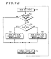
- the slave microprocessor 502 can send either a flip element closed indication or a flip open indication to the radio microcomputer, a detection of those indications is necessary by the radio microcomputer.
- the slave microprocessor 502 determines, as part of its routine of chores, whether the hookswitch has changed state by comparing the current state against the stored state at 722 and 724 of Fig. 7B. If the state is different, then a determination is made, at 726, whether the flip element is open or closed. If the flip element is determined to be open, then an open flip element command is transmitted to the radio microcomputer at 728 and the slave microprocessor returns to its normal background functions at 732. If the determination at 726 yields a closed flip element, then a closed flip element command is conveyed to the radio microcomputer at 730 and the slave microprocessor returns to its normal background functions at 732.
- the radio microcomputer 404 maintains the flip element state in its associated storage and the slave microprocessor 502, as part of its routine of chores, checks for a keypad enable or a keypad disable command received from the radio microcomputer 404. Thus, if the flip element is determined to be open, then the keys of the keypad are read in conventional fashion. If the flip element is determined to be closed, then the keys of the keypad are ignored.
- the radio microprocessor 404 checks for a on-hook to off-hook transition at 804. If an on-hook to off-hook transition has not occurred then flow proceeds to determination block 806 where a test is made to determine if an off-hook to on-hook transition has occurred. If none has occurred, then flow returns to the normal background functions at 802. If it is determined that an off-hook to on-hook transition has occurred at 806 indicating that the movable element 104 is in the closed position, then flow proceeds to determination block 808 where a test is made to determine if a telephone call is presently in progress.
- the voice recognition circuitry, the backlighting, and the display are inactivated.
- the display may remain activated for a period of six seconds before being deactivated by such a off-hook to on-hook transition. From 810, flow returns to the normal background functions at 802. If a determination is made that a call is in progress, at 808, then flow proceeds to determination block 812. A test is made, at 812, of whether the microphone mute function is on.
- the voice recognition circuitry is disabled.
- the timer duration 'n' is 1000 milliseconds.
- Flow proceeds from block 820 to 802 where flow returns to the normal background functions. If it is determined, at 818, that the timer has not expired, then flow proceeds to determination block 822 where a test is made of whether an on-hook to off-hook transition has occurred. If no on-hook to off-hook transition has occurred, then flow returns to determination block 818. Flow continues in the 818-822 loop until either the timer expires or an on-hook to off-hook transition occurs.
- the flow proceeds to block 834 where the voice recognition circuitry is activated.
- the process then, at 835, activates the keypad backlighting illumination and the display 416 for a conventionally timed period of six seconds.
- the voice recognition circuitry is activated, the keypad backlighting is activated, the display is activated.
- the flow continues to determination block 836.
- a test is made, at 836, to determine whether the microphone mute function is on. If it was determined, at 836, that the microphone is muted, then flow proceeds to block 838 where the microphone is unmuted.
- the microphone is in the muted state with the movable element closed, opening the movable element will unmute the microphone, from 838 flow returns to the normal background functions at 802.
- a test is made, at 840, to determine whether the portable radiotelephone is currently ringing. If it is determined, at 840, that the portable radiotelephone is not ringing, indicating that there is no incoming call, then the process flow returns to the normal background functions at 802. If it is determined, at 840, that the radiotelephone is ringing, then the process flow proceeds to block 842 where the incoming call is answered. Thus, if the telephone is ringing while the movable flip element 104 is closed and the movable element 104 is then opened, the incoming call is answered. From 842, flow returns to the normal background functions at 802.
- a portable radiotelephone having the capability of enabling and disabling voice recognition circuitry in response to the position of a flip element has been shown and described.
- the flip element which covers a keypad and other control buttons when in a closed position, produces an off-hook condition via a hookswitch when moved to an open position. While a particular embodiment of the invention has been shown and described, it is to be understood that the invention is not to be taken as limited to the specific embodiment herein, and that changes and modifications may be made by a person skilled in the art without departing from the scope of the invention.
Landscapes
- Engineering & Computer Science (AREA)
- Signal Processing (AREA)
- Human Computer Interaction (AREA)
- Mobile Radio Communication Systems (AREA)
- Input Circuits Of Receivers And Coupling Of Receivers And Audio Equipment (AREA)
- Selective Calling Equipment (AREA)
- Telephone Set Structure (AREA)
- Transceivers (AREA)
- Fittings On The Vehicle Exterior For Carrying Loads, And Devices For Holding Or Mounting Articles (AREA)
- Telephone Function (AREA)
- Telephonic Communication Services (AREA)
- Communication Control (AREA)
Claims (4)
- Appareil radiotéléphonique portable ayant un circuit de reconnaissance vocale et ayant en outre un boítier possédant un élément mobile (104) et un élément fixe (102), l'élément mobile ayant une première position repliée et une deuxième position dépliée, l'appareil radiotéléphonique portable comprenant :un moyen permettant de produire (306) un signal de décrochage dans l'appareil radiotéléphonique portable lorsque l'élément mobile se trouve dans le deuxième position ;un moyen permettant d'activer (414) le circuit de reconnaissance vocale lorsque l'élément mobile se trouve dans la deuxième position ; etun moyen permettant d'initier (404) un appel téléphonique une fois que ledit état de décrochage a été produit ;un moyen permettant de désactiver (414) un circuit de reconnaissance vocale activé mais de conserver ledit appel téléphonique lorsque l'élément mobile est placé dans la première position puis qu'il retourne dans la deuxième position au bout d'une période de temps prédéterminée ; etun moyen permettant de produire (306) un état de raccrochage dans l'appareil radiotéléphonique portable si l'élément mobile se trouve dans la première position.
- Appareil radiotéléphonique portable selon la revendication 1, caractérisé en outre par un moyen permettant de désactiver (414) un circuit de reconnaissance vocale activé lorsque l'élément mobile se trouve dans la première position.
- Procédé de commande d'un circuit de reconnaissance vocale dans un appareil radiotéléphonique portable ayant un pavé de touches (110) et un élément mobile (104) qui est mobile entre une première position et une deuxième position, caractérisé par les étapes consistant à :produire (728) un signal de décrochage dans l'appareil radiotéléphonique portable si l'élément mobile se trouve dans la deuxième position ;activer (834) le circuit de reconnaissance vocale lorsque l'élément mobile se trouve dans la deuxième position ;initier (822) un appel téléphonique après que ledit état de décrochage s'est produit ;désactiver (825) un circuit de reconnaissance vocale activé mais en maintenant ledit appel téléphonique initié lorsque l'élément mobile est placé dans la première position puis qu'il se replace dans la deuxième position en une période de temps prédéterminée ; etproduire (730) un état de raccrochage dans l'appareil radiotéléphonique portable si l'élément mobile se trouve dans la première position.
- Procédé selon le procédé de la revendication 3, caractérisé en outre par l'étape consistant à désactiver (810) un circuit de reconnaissance vocale activé lorsque l'élément mobile est placé dans la première position.
Applications Claiming Priority (3)
| Application Number | Priority Date | Filing Date | Title |
|---|---|---|---|
| US439993 | 1989-11-20 | ||
| US07/439,993 US5148471A (en) | 1989-11-20 | 1989-11-20 | Communications device with voice recognition and movable element control interface |
| PCT/US1990/006222 WO1991007835A1 (fr) | 1989-11-20 | 1990-11-01 | Dispositif de communications a reconnaissance de la voix et a interface de commande a element mobile |
Publications (3)
| Publication Number | Publication Date |
|---|---|
| EP0454814A1 EP0454814A1 (fr) | 1991-11-06 |
| EP0454814A4 EP0454814A4 (en) | 1993-02-24 |
| EP0454814B1 true EP0454814B1 (fr) | 1998-06-10 |
Family
ID=23746981
Family Applications (1)
| Application Number | Title | Priority Date | Filing Date |
|---|---|---|---|
| EP90916542A Expired - Lifetime EP0454814B1 (fr) | 1989-11-20 | 1990-11-01 | Dispositif de communications a reconnaissance de la voix et a interface de commande a element mobile |
Country Status (11)
| Country | Link |
|---|---|
| US (1) | US5148471A (fr) |
| EP (1) | EP0454814B1 (fr) |
| CN (1) | CN1021691C (fr) |
| AT (1) | ATE167345T1 (fr) |
| AU (1) | AU626475B2 (fr) |
| CA (1) | CA2045399C (fr) |
| DE (1) | DE69032401T2 (fr) |
| DK (1) | DK0454814T3 (fr) |
| ES (1) | ES2116985T3 (fr) |
| SG (1) | SG52277A1 (fr) |
| WO (1) | WO1991007835A1 (fr) |
Families Citing this family (89)
| Publication number | Priority date | Publication date | Assignee | Title |
|---|---|---|---|---|
| US5247565A (en) * | 1989-05-10 | 1993-09-21 | Motorola, Inc. | Cellular telephone with keypad controller |
| DE4022511A1 (de) * | 1990-07-14 | 1992-01-16 | Grundig Emv | Sprachgesteuertes geraet der unterhaltungselektronik insbesondere videorecorder |
| JPH04207341A (ja) * | 1990-11-30 | 1992-07-29 | Sony Corp | 無線電話装置 |
| JP2707854B2 (ja) * | 1991-02-06 | 1998-02-04 | 日本電気株式会社 | 移動電話機 |
| FI88657C (fi) * | 1991-02-12 | 1993-06-10 | Nokia Mobile Phones Ltd | Foerfarande foer att minska stroemfoerbrukningen i en mobiltelefon |
| EP0502617B1 (fr) * | 1991-03-06 | 1998-04-15 | Nokia Mobile Phones (U.K.) Limited | Téléphone portable |
| JP2584137B2 (ja) * | 1991-03-11 | 1997-02-19 | 松下電器産業株式会社 | 携帯形無線機 |
| US5259019A (en) * | 1991-04-08 | 1993-11-02 | Texas Instruments Incorporated | Apparatus providing for a curved device with hinged cover |
| JP3222503B2 (ja) * | 1991-10-03 | 2001-10-29 | 株式会社東芝 | 無線電話機および無線電話システム |
| GB2264209B (en) * | 1992-02-06 | 1995-11-08 | Technophone Ltd | Cordless telephone arrangement |
| US5371779A (en) * | 1992-03-13 | 1994-12-06 | Nec Corporation | Call initiating system for mobile telephone units |
| US5297183A (en) * | 1992-04-13 | 1994-03-22 | Vcs Industries, Inc. | Speech recognition system for electronic switches in a cellular telephone or personal communication network |
| US5365570A (en) * | 1992-06-02 | 1994-11-15 | Boubelik Mark J | Emergency cellular telephone apparatus |
| US5450525A (en) * | 1992-11-12 | 1995-09-12 | Russell; Donald P. | Vehicle accessory control with manual and voice response |
| US6192255B1 (en) * | 1992-12-15 | 2001-02-20 | Texas Instruments Incorporated | Communication system and methods for enhanced information transfer |
| US5625684A (en) * | 1993-02-04 | 1997-04-29 | Local Silence, Inc. | Active noise suppression system for telephone handsets and method |
| US5722040A (en) * | 1993-02-04 | 1998-02-24 | Pacific Communication Sciences, Inc. | Method and apparatus of frequency generation for use with digital cordless telephones |
| US5606594A (en) * | 1994-01-27 | 1997-02-25 | Dell Usa, L.P. | Communication accessory and method of telecommunicating for a PDA |
| JP2606142B2 (ja) * | 1994-06-15 | 1997-04-30 | 日本電気株式会社 | ディジタル携帯電話機 |
| US5724663A (en) * | 1994-08-16 | 1998-03-03 | Hyundai Motor Company, Ltd. | Car phone connected to a vehicle audio unit having visual indication |
| US5930352A (en) * | 1994-08-31 | 1999-07-27 | Sony Corporation | Communication terminal apparatus |
| EP0795246A4 (fr) * | 1994-12-02 | 2000-04-26 | Voice Control Systems Inc | Unite intelligente de traitement d'appels pour systeme telephonique domestique |
| US6167253A (en) * | 1995-01-12 | 2000-12-26 | Bell Atlantic Network Services, Inc. | Mobile data/message/electronic mail download system utilizing network-centric protocol such as Java |
| US6151491A (en) * | 1995-01-12 | 2000-11-21 | Bell Atlantic Network Services, Inc. | Mobile voice message/electronic mail system |
| US5594779A (en) * | 1995-01-12 | 1997-01-14 | Bell Atlantic | Mobile audio program selection system using public switched telephone network |
| US6029064A (en) * | 1995-01-12 | 2000-02-22 | Bell Atlantic Network Services, Inc. | Mobile audio program selection system using public switched telephone network |
| DE29505758U1 (de) * | 1995-04-04 | 1996-08-01 | Max A Horn Ind Automation | Vorrichtung zum Herstellen von Verbindungen zwischen Telekommunikationsteilnehmern |
| US5701338A (en) * | 1995-04-11 | 1997-12-23 | Dnb Dataware Sciences, Inc. Technologies | Call box with keyboard communication |
| USD384059S (en) * | 1995-04-11 | 1997-09-23 | E.F. Johnson Company | Handheld two-way radio with hinged cover |
| US5678206A (en) * | 1995-04-12 | 1997-10-14 | E. F. Johnson Company | Keypad cover hinge |
| US5651056A (en) * | 1995-07-13 | 1997-07-22 | Eting; Leon | Apparatus and methods for conveying telephone numbers and other information via communication devices |
| USD397109S (en) | 1995-08-25 | 1998-08-18 | E. F. Johnson Company | Handheld two-way radio with hinged cover |
| WO1997011435A2 (fr) * | 1995-09-04 | 1997-03-27 | British Telecommunications Public Limited Company | Dispositif de support de transactions |
| US5918180A (en) * | 1995-12-22 | 1999-06-29 | Dimino; Michael | Telephone operable global tracking system for vehicles |
| US5719921A (en) * | 1996-02-29 | 1998-02-17 | Nynex Science & Technology | Methods and apparatus for activating telephone services in response to speech |
| US6073027A (en) * | 1996-08-29 | 2000-06-06 | Bellsouth Corporation | Portable radiotelephone with sliding cover and automatic antenna extension |
| CA2269027A1 (fr) * | 1996-10-17 | 1998-04-23 | Andrea Electronics Corporation | Amelioration acoustique de l'elimination du bruit pour les radiotelephones cellulaires ou les telephones cellulaires |
| EP0885513A1 (fr) * | 1996-12-17 | 1998-12-23 | Koninklijke Philips Electronics N.V. | Telephone sans fil |
| US6128514A (en) | 1997-01-31 | 2000-10-03 | Bellsouth Corporation | Portable radiotelephone for automatically dialing a central voice-activated dialing system |
| GB2321823B (en) * | 1997-02-04 | 1999-05-12 | Sack Chan | Audio sending device for a mobile telephone |
| BE1011293A3 (fr) * | 1997-02-21 | 1999-07-06 | Staar Dev Co Sa | Systeme d'instructions pour telephone mobile. |
| US6125286A (en) * | 1997-06-05 | 2000-09-26 | Motorola, Inc. | Communication device having multiple displays and method of operating the same |
| JP2944582B2 (ja) * | 1997-06-25 | 1999-09-06 | 埼玉日本電気株式会社 | 折り畳み型携帯電話機 |
| US6094565A (en) * | 1997-06-30 | 2000-07-25 | Motorola, Inc. | Closeable communication device and method of operating the same |
| JP3055514B2 (ja) * | 1997-12-05 | 2000-06-26 | 日本電気株式会社 | 電話回線用音声認識装置 |
| JPH11249692A (ja) * | 1998-02-27 | 1999-09-17 | Nec Saitama Ltd | 音声認識装置 |
| US6505159B1 (en) | 1998-03-03 | 2003-01-07 | Microsoft Corporation | Apparatus and method for providing speech input to a speech recognition system |
| SE9801379L (sv) * | 1998-04-21 | 1999-10-22 | Ericsson Telefon Ab L M | Inmatningsenhet och metod för att mata in data i en elektronisk apparat |
| US6240303B1 (en) | 1998-04-23 | 2001-05-29 | Motorola Inc. | Voice recognition button for mobile telephones |
| US6229880B1 (en) | 1998-05-21 | 2001-05-08 | Bell Atlantic Network Services, Inc. | Methods and apparatus for efficiently providing a communication system with speech recognition capabilities |
| US6233315B1 (en) | 1998-05-21 | 2001-05-15 | Bell Atlantic Network Services, Inc. | Methods and apparatus for increasing the utility and interoperability of peripheral devices in communications systems |
| SE9801970L (sv) | 1998-06-03 | 1999-12-04 | Ericsson Telefon Ab L M | Mobil elektronisk anordning |
| FI104221B1 (fi) | 1998-06-30 | 1999-11-30 | Nokia Mobile Phones Ltd | Kaksiosainen elektroninen laite |
| US7003463B1 (en) | 1998-10-02 | 2006-02-21 | International Business Machines Corporation | System and method for providing network coordinated conversational services |
| US6744860B1 (en) | 1998-12-31 | 2004-06-01 | Bell Atlantic Network Services | Methods and apparatus for initiating a voice-dialing operation |
| US6233557B1 (en) | 1999-02-23 | 2001-05-15 | Motorola, Inc. | Method of selectively assigning a penalty to a probability associated with a voice recognition system |
| JP2000244625A (ja) * | 1999-02-23 | 2000-09-08 | Nec Saitama Ltd | 携帯電話機における音声認識起動方法及び音声認識携帯電話装置 |
| KR100663572B1 (ko) * | 1999-07-06 | 2007-01-02 | 삼성전자주식회사 | 자동 접이형 휴대용 단말기 |
| IT1313528B1 (it) * | 1999-09-20 | 2002-07-24 | Telital Spa | Telefoni cellulari con parte di potenza separabile e rete di telefonia con essi |
| KR100339339B1 (ko) * | 1999-10-28 | 2002-06-03 | 서평원 | 전화기에서 음성 인식 기능 제어 방법 |
| GB2356760B (en) | 1999-11-23 | 2004-06-23 | Nokia Mobile Phones Ltd | A radiotelephone handset |
| GB2358987B (en) * | 2000-02-01 | 2003-10-29 | Ericsson Telefon Ab L M | Electronic devices |
| KR20010094229A (ko) * | 2000-04-04 | 2001-10-31 | 이수성 | 전화기의 음성인식 조작 방법 및 시스템 |
| AUPQ724600A0 (en) * | 2000-05-02 | 2000-05-25 | Rojone Pty Limited | Personal monitoring system |
| AU2001266910A1 (en) * | 2000-06-14 | 2001-12-24 | Sleep Solutions, Inc. | Secure medical test and result delivery system |
| US7151912B1 (en) * | 2000-11-07 | 2006-12-19 | Morrison Mark D | Cable retractor for an electronic device |
| US20040181415A1 (en) * | 2001-01-19 | 2004-09-16 | Imet Corporation | Speech activated telephone device for connection to existing landline phone |
| US6885735B2 (en) * | 2001-03-29 | 2005-04-26 | Intellisist, Llc | System and method for transmitting voice input from a remote location over a wireless data channel |
| EP1393535A1 (fr) * | 2001-05-08 | 2004-03-03 | Koninklijke Philips Electronics N.V. | Telephone ayant une fonction de ligne en attente |
| US7395089B1 (en) | 2001-06-11 | 2008-07-01 | Palm, Inc | Integrated personal digital assistant device |
| US7356361B1 (en) * | 2001-06-11 | 2008-04-08 | Palm, Inc. | Hand-held device |
| US6975304B1 (en) | 2001-06-11 | 2005-12-13 | Handspring, Inc. | Interface for processing of an alternate symbol in a computer device |
| US7366673B2 (en) * | 2001-06-15 | 2008-04-29 | International Business Machines Corporation | Selective enablement of speech recognition grammars |
| US20030203731A1 (en) * | 2002-04-29 | 2003-10-30 | Lavaflow, Llp | Cellular telephone and method of displaying account information |
| US7242765B2 (en) * | 2002-06-28 | 2007-07-10 | Tommy Lee Hairston | Headset cellular telephones |
| AU2003283971A1 (en) * | 2002-09-30 | 2004-04-23 | Simple Products Inc. | Multiple piece wireless phone |
| US20060178159A1 (en) * | 2005-02-07 | 2006-08-10 | Don Timms | Voice activated push-to-talk device and method of use |
| US7330122B2 (en) | 2005-08-10 | 2008-02-12 | Remotemdx, Inc. | Remote tracking and communication device |
| US7936262B2 (en) | 2006-07-14 | 2011-05-03 | Securealert, Inc. | Remote tracking system with a dedicated monitoring center |
| US8797210B2 (en) | 2006-07-14 | 2014-08-05 | Securealert, Inc. | Remote tracking device and a system and method for two-way voice communication between the device and a monitoring center |
| US7737841B2 (en) | 2006-07-14 | 2010-06-15 | Remotemdx | Alarm and alarm management system for remote tracking devices |
| EP2260482B1 (fr) | 2008-03-07 | 2013-01-09 | Securealert, Inc. | Système et procédé destinés à la surveillance d individus grâce à une balise et à un dispositif de localisation à distance intelligent |
| US8514070B2 (en) | 2010-04-07 | 2013-08-20 | Securealert, Inc. | Tracking device incorporating enhanced security mounting strap |
| CN101892433A (zh) * | 2010-06-25 | 2010-11-24 | 南京钢铁股份有限公司 | 一种耐低温硫酸露点腐蚀的低合金钢 |
| US10032455B2 (en) | 2011-01-07 | 2018-07-24 | Nuance Communications, Inc. | Configurable speech recognition system using a pronunciation alignment between multiple recognizers |
| CN102833416B (zh) * | 2012-08-29 | 2014-11-05 | 惠州Tcl移动通信有限公司 | 一种手机翻转静音控制的方法及手机 |
| US9565539B2 (en) * | 2012-09-28 | 2017-02-07 | Kyocera Corporation | Electronic device and call transfer control method |
| CN104769668B (zh) | 2012-10-04 | 2018-10-30 | 纽昂斯通讯公司 | 改进的用于asr的混合控制器 |
| US10971157B2 (en) | 2017-01-11 | 2021-04-06 | Nuance Communications, Inc. | Methods and apparatus for hybrid speech recognition processing |
Family Cites Families (18)
| Publication number | Priority date | Publication date | Assignee | Title |
|---|---|---|---|---|
| BE631733A (fr) * | 1962-05-04 | |||
| US3476866A (en) * | 1965-08-11 | 1969-11-04 | Baldwin Co D H | Low-pitched voices in electronic organs |
| NL292251A (fr) * | 1966-01-29 | |||
| US3821718A (en) * | 1972-10-25 | 1974-06-28 | Gte Automatic Electric Lab Inc | Trunk timer with exact time feature |
| DE2504314A1 (de) * | 1975-02-03 | 1976-08-05 | Elmeg | Nachrichten-peripherie-einrichtung, insbesondere fernsprechapparat oder pruefhandapparat |
| DE2941928C2 (de) * | 1979-10-17 | 1986-04-10 | Telefonbau Und Normalzeit Gmbh, 6000 Frankfurt | Schaltungsanordnung für eine Fernsprechteilnehmerstation |
| US4348550A (en) * | 1980-06-09 | 1982-09-07 | Bell Telephone Laboratories, Incorporated | Spoken word controlled automatic dialer |
| US4471493A (en) * | 1982-12-16 | 1984-09-11 | Gte Automatic Electric Inc. | Wireless telephone extension unit with self-contained dipole antenna |
| JPS60230723A (ja) * | 1984-04-27 | 1985-11-16 | エルヴイン・ブランデンシユタイン | 無線電話幾 |
| FR2571191B1 (fr) * | 1984-10-02 | 1986-12-26 | Renault | Systeme de radiotelephone, notamment pour vehicule automobile |
| US4845772A (en) * | 1988-06-13 | 1989-07-04 | Motorola, Inc. | Portable radiotelephone with control switch disabling |
| WO1987001546A1 (fr) * | 1985-09-03 | 1987-03-12 | Motorola, Inc. | Systeme de commande non-manuel pour radiotelephones |
| US4873714A (en) * | 1985-11-26 | 1989-10-10 | Kabushiki Kaisha Toshiba | Speech recognition system with an accurate recognition function |
| JPH0815353B2 (ja) * | 1986-10-30 | 1996-02-14 | 日本電気株式会社 | コ−ドレス電話装置 |
| JPS63299555A (ja) * | 1987-05-29 | 1988-12-07 | Toshiba Corp | 無線電話装置 |
| US4959850A (en) * | 1987-05-29 | 1990-09-25 | Kabushiki Kaisha Toshiba | Radio telephone apparatus |
| EP0307193B1 (fr) * | 1987-09-11 | 1993-11-18 | Kabushiki Kaisha Toshiba | Appareil téléphonique |
| JPH0243855A (ja) * | 1988-08-04 | 1990-02-14 | Toshiba Corp | 無線電話装置 |
-
1989
- 1989-11-20 US US07/439,993 patent/US5148471A/en not_active Expired - Lifetime
-
1990
- 1990-11-01 DK DK90916542T patent/DK0454814T3/da active
- 1990-11-01 AU AU66473/90A patent/AU626475B2/en not_active Ceased
- 1990-11-01 SG SG1996001808A patent/SG52277A1/en unknown
- 1990-11-01 ES ES90916542T patent/ES2116985T3/es not_active Expired - Lifetime
- 1990-11-01 EP EP90916542A patent/EP0454814B1/fr not_active Expired - Lifetime
- 1990-11-01 AT AT90916542T patent/ATE167345T1/de not_active IP Right Cessation
- 1990-11-01 CA CA002045399A patent/CA2045399C/fr not_active Expired - Fee Related
- 1990-11-01 WO PCT/US1990/006222 patent/WO1991007835A1/fr active IP Right Grant
- 1990-11-01 DE DE69032401T patent/DE69032401T2/de not_active Expired - Fee Related
- 1990-11-17 CN CN90109187A patent/CN1021691C/zh not_active Expired - Fee Related
Also Published As
| Publication number | Publication date |
|---|---|
| AU626475B2 (en) | 1992-07-30 |
| ES2116985T3 (es) | 1998-08-01 |
| CN1052016A (zh) | 1991-06-05 |
| CN1021691C (zh) | 1993-07-21 |
| DE69032401T2 (de) | 1998-12-03 |
| CA2045399C (fr) | 1995-11-28 |
| CA2045399A1 (fr) | 1991-05-21 |
| US5148471A (en) | 1992-09-15 |
| AU6647390A (en) | 1991-06-13 |
| SG52277A1 (en) | 1998-09-28 |
| DK0454814T3 (da) | 1999-03-29 |
| WO1991007835A1 (fr) | 1991-05-30 |
| EP0454814A1 (fr) | 1991-11-06 |
| ATE167345T1 (de) | 1998-06-15 |
| EP0454814A4 (en) | 1993-02-24 |
| DE69032401D1 (de) | 1998-07-16 |
Similar Documents
| Publication | Publication Date | Title |
|---|---|---|
| EP0454814B1 (fr) | Dispositif de communications a reconnaissance de la voix et a interface de commande a element mobile | |
| US5175759A (en) | Communications device with movable element control interface | |
| US4845772A (en) | Portable radiotelephone with control switch disabling | |
| US5898933A (en) | Apparatus and method for generating a control signal responsive to a movable antenna | |
| KR0129713B1 (ko) | 휴대용 통신장치 | |
| US6148213A (en) | Method and apparatus for accessing a telephone answering device from a cordless telephone portable unit | |
| US5493604A (en) | Portable telephone set with automatic dialing feature | |
| US5953656A (en) | Method and apparatus for remotely accessing a telephone answering device | |
| KR920003296B1 (ko) | 무선전화시스템 | |
| US5884185A (en) | Cordless telephone having a call key capable of performing multiple functions and a method for assigning alternate functions to the call key and performing the multiple functions | |
| KR920009332B1 (ko) | 무선 전화기 | |
| JP3014943B2 (ja) | 電子システム手帳型携帯電話装置 | |
| KR100226222B1 (ko) | 이어-마이크 접속 감지를 통한 자동 착신전환기능을 갖춘 무선전화기 | |
| KR900002471Y1 (ko) | 키폰 시스템의 묵음방식 | |
| KR200266290Y1 (ko) | 휴대폰의 핸즈프리키트 | |
| JPH0537557Y2 (fr) | ||
| JPS61281656A (ja) | 電話機システム | |
| KR19990005402A (ko) | 라디오 청취기능을 갖는 무선헤드폰전화기 | |
| JPH02214355A (ja) | 電話装置 | |
| JPH10136068A (ja) | 無線通信機のハンドセット | |
| KR19990058028A (ko) | 이동무선전화기의 음성에 의한 조작방법 | |
| KR19980043311A (ko) | 카 오디오를 이용한 무선전화기 제어장치 및 그 제어방법 | |
| KR20060017041A (ko) | 휴대용 단말기의 통화음량 조절장치 |
Legal Events
| Date | Code | Title | Description |
|---|---|---|---|
| PUAI | Public reference made under article 153(3) epc to a published international application that has entered the european phase |
Free format text: ORIGINAL CODE: 0009012 |
|
| 17P | Request for examination filed |
Effective date: 19910718 |
|
| AK | Designated contracting states |
Kind code of ref document: A1 Designated state(s): AT DE DK ES FR GB IT SE |
|
| A4 | Supplementary search report drawn up and despatched |
Effective date: 19930107 |
|
| AK | Designated contracting states |
Kind code of ref document: A4 Designated state(s): AT DE DK ES FR GB IT SE |
|
| 17Q | First examination report despatched |
Effective date: 19950310 |
|
| GRAG | Despatch of communication of intention to grant |
Free format text: ORIGINAL CODE: EPIDOS AGRA |
|
| GRAG | Despatch of communication of intention to grant |
Free format text: ORIGINAL CODE: EPIDOS AGRA |
|
| GRAH | Despatch of communication of intention to grant a patent |
Free format text: ORIGINAL CODE: EPIDOS IGRA |
|
| GRAH | Despatch of communication of intention to grant a patent |
Free format text: ORIGINAL CODE: EPIDOS IGRA |
|
| GRAA | (expected) grant |
Free format text: ORIGINAL CODE: 0009210 |
|
| ITF | It: translation for a ep patent filed |
Owner name: BARZANO' E ZANARDO ROMA S.P.A. |
|
| AK | Designated contracting states |
Kind code of ref document: B1 Designated state(s): AT DE DK ES FR GB IT SE |
|
| REF | Corresponds to: |
Ref document number: 167345 Country of ref document: AT Date of ref document: 19980615 Kind code of ref document: T |
|
| REF | Corresponds to: |
Ref document number: 69032401 Country of ref document: DE Date of ref document: 19980716 |
|
| ET | Fr: translation filed | ||
| REG | Reference to a national code |
Ref country code: ES Ref legal event code: FG2A Ref document number: 2116985 Country of ref document: ES Kind code of ref document: T3 |
|
| REG | Reference to a national code |
Ref country code: DK Ref legal event code: T3 |
|
| PLBE | No opposition filed within time limit |
Free format text: ORIGINAL CODE: 0009261 |
|
| STAA | Information on the status of an ep patent application or granted ep patent |
Free format text: STATUS: NO OPPOSITION FILED WITHIN TIME LIMIT |
|
| 26N | No opposition filed | ||
| PGFP | Annual fee paid to national office [announced via postgrant information from national office to epo] |
Ref country code: DK Payment date: 20000919 Year of fee payment: 11 |
|
| PGFP | Annual fee paid to national office [announced via postgrant information from national office to epo] |
Ref country code: AT Payment date: 20001003 Year of fee payment: 11 |
|
| PGFP | Annual fee paid to national office [announced via postgrant information from national office to epo] |
Ref country code: DE Payment date: 20001014 Year of fee payment: 11 |
|
| PGFP | Annual fee paid to national office [announced via postgrant information from national office to epo] |
Ref country code: SE Payment date: 20001103 Year of fee payment: 11 |
|
| PGFP | Annual fee paid to national office [announced via postgrant information from national office to epo] |
Ref country code: ES Payment date: 20001121 Year of fee payment: 11 |
|
| PG25 | Lapsed in a contracting state [announced via postgrant information from national office to epo] |
Ref country code: AT Free format text: LAPSE BECAUSE OF NON-PAYMENT OF DUE FEES Effective date: 20011101 Ref country code: DK Free format text: LAPSE BECAUSE OF NON-PAYMENT OF DUE FEES Effective date: 20011101 |
|
| PG25 | Lapsed in a contracting state [announced via postgrant information from national office to epo] |
Ref country code: ES Free format text: LAPSE BECAUSE OF NON-PAYMENT OF DUE FEES Effective date: 20011102 Ref country code: SE Free format text: LAPSE BECAUSE OF NON-PAYMENT OF DUE FEES Effective date: 20011102 |
|
| REG | Reference to a national code |
Ref country code: GB Ref legal event code: IF02 |
|
| EUG | Se: european patent has lapsed |
Ref document number: 90916542.5 |
|
| PG25 | Lapsed in a contracting state [announced via postgrant information from national office to epo] |
Ref country code: DE Free format text: LAPSE BECAUSE OF NON-PAYMENT OF DUE FEES Effective date: 20020702 |
|
| REG | Reference to a national code |
Ref country code: DK Ref legal event code: EBP |
|
| REG | Reference to a national code |
Ref country code: ES Ref legal event code: FD2A Effective date: 20021213 |
|
| PGFP | Annual fee paid to national office [announced via postgrant information from national office to epo] |
Ref country code: GB Payment date: 20061004 Year of fee payment: 17 |
|
| PGFP | Annual fee paid to national office [announced via postgrant information from national office to epo] |
Ref country code: FR Payment date: 20061103 Year of fee payment: 17 |
|
| PGFP | Annual fee paid to national office [announced via postgrant information from national office to epo] |
Ref country code: IT Payment date: 20061130 Year of fee payment: 17 |
|
| GBPC | Gb: european patent ceased through non-payment of renewal fee |
Effective date: 20071101 |
|
| REG | Reference to a national code |
Ref country code: FR Ref legal event code: ST Effective date: 20080930 |
|
| PG25 | Lapsed in a contracting state [announced via postgrant information from national office to epo] |
Ref country code: GB Free format text: LAPSE BECAUSE OF NON-PAYMENT OF DUE FEES Effective date: 20071101 |
|
| PG25 | Lapsed in a contracting state [announced via postgrant information from national office to epo] |
Ref country code: FR Free format text: LAPSE BECAUSE OF NON-PAYMENT OF DUE FEES Effective date: 20071130 |
|
| PG25 | Lapsed in a contracting state [announced via postgrant information from national office to epo] |
Ref country code: IT Free format text: LAPSE BECAUSE OF NON-PAYMENT OF DUE FEES Effective date: 20071101 |
|
| P01 | Opt-out of the competence of the unified patent court (upc) registered |
Effective date: 20230520 |