EP0454093A2 - Spindelausführung zur Halterung und Drehung eines Werkstückes - Google Patents
Spindelausführung zur Halterung und Drehung eines Werkstückes Download PDFInfo
- Publication number
- EP0454093A2 EP0454093A2 EP19910106609 EP91106609A EP0454093A2 EP 0454093 A2 EP0454093 A2 EP 0454093A2 EP 19910106609 EP19910106609 EP 19910106609 EP 91106609 A EP91106609 A EP 91106609A EP 0454093 A2 EP0454093 A2 EP 0454093A2
- Authority
- EP
- European Patent Office
- Prior art keywords
- workpiece
- spindle
- ram
- rotation
- moved
- Prior art date
- Legal status (The legal status is an assumption and is not a legal conclusion. Google has not performed a legal analysis and makes no representation as to the accuracy of the status listed.)
- Ceased
Links
Images


Classifications
-
- B—PERFORMING OPERATIONS; TRANSPORTING
- B24—GRINDING; POLISHING
- B24B—MACHINES, DEVICES, OR PROCESSES FOR GRINDING OR POLISHING; DRESSING OR CONDITIONING OF ABRADING SURFACES; FEEDING OF GRINDING, POLISHING, OR LAPPING AGENTS
- B24B41/00—Component parts such as frames, beds, carriages, headstocks
- B24B41/06—Work supports, e.g. adjustable steadies
-
- B—PERFORMING OPERATIONS; TRANSPORTING
- B24—GRINDING; POLISHING
- B24B—MACHINES, DEVICES, OR PROCESSES FOR GRINDING OR POLISHING; DRESSING OR CONDITIONING OF ABRADING SURFACES; FEEDING OF GRINDING, POLISHING, OR LAPPING AGENTS
- B24B19/00—Single-purpose machines or devices for particular grinding operations not covered by any other main group
- B24B19/08—Single-purpose machines or devices for particular grinding operations not covered by any other main group for grinding non-circular cross-sections, e.g. shafts of elliptical or polygonal cross-section
- B24B19/12—Single-purpose machines or devices for particular grinding operations not covered by any other main group for grinding non-circular cross-sections, e.g. shafts of elliptical or polygonal cross-section for grinding cams or camshafts
-
- B—PERFORMING OPERATIONS; TRANSPORTING
- B24—GRINDING; POLISHING
- B24B—MACHINES, DEVICES, OR PROCESSES FOR GRINDING OR POLISHING; DRESSING OR CONDITIONING OF ABRADING SURFACES; FEEDING OF GRINDING, POLISHING, OR LAPPING AGENTS
- B24B41/00—Component parts such as frames, beds, carriages, headstocks
- B24B41/06—Work supports, e.g. adjustable steadies
- B24B41/061—Work supports, e.g. adjustable steadies axially supporting turning workpieces, e.g. magnetically, pneumatically
Definitions
- the present invention relates to a spindle apparatus for supporting and rotating a workpiece, particularly, wherein a spindle center can be displaced in the axial direction of a spindle.
- a cylindrical grinder designed to grind a cylindrical workpiece or a cam grinder is generally constructed as shown in Fig. 1.
- a wheel head 102 and a table 103 are arranged on a bed 101 and are slidable along guides in vertical and lateral directions in the drawing, respectively.
- a wheel shaft 105 is supported on the wheel head 102 and is driven for rotation by a motor 106 through a belt-and-pulley mechanism 107.
- a pair of grinding wheels 104a and 104b are mounted to the wheel shaft 105.
- a spindle head 110 is mounted on one end of the table 103.
- a workpiece spindle 109 is supported by the spindle head 110 and driven in rotation from a motor 108.
- the workpiece spindle 109 includes a chuck and a center 129.
- Mounted on the other end of the table 103 is a tailstock 113 including a tailstock spindle 112.
- the tailstock spindle 112 includes a center 111 in a face-to-face relation to the workpiece spindle 109.
- a pair of workpiece stand-by stations 114a and 114b are located on the table 103 adjacent to front ends of the workpiece spindle 109 and the tailstock spindle 112.
- An instrument 115 is provided on the bed 101 to sense the axial or longitudinal position of a workpiece.
- a workpiece shifter 150 is located on the table 103 between the workpiece spindle 109 and the tailstock spindle 112.
- the tailstock spindle 112 or the center 111 is in its retreated position before abrasive action is initiated.
- a workpiece W is loaded temporarily on the workpiece stand-by stations 115a and 115b by a loader or similar means.
- the workpiece W is thereafter moved toward the workpiece spindle 109 by the workpiece shifter 150 until one end of the workpiece W is brought into engagement with the center 129 of the workpiece spindle 109.
- the tailstock spindle 112 is then advanced so that the other end of the workpiece W is brought into engagement with the center 111.
- the end of the workpiece adjacent to the workpiece spindle is gripped by the chuck of the workpiece spindle 109.
- the wheel head 102 is advanced while the workpiece W is being rotated by the motor 108.
- the workpiece W is then abraded by the grinding wheels 104a and 104b which are rotated by the motor 106.
- the wheel head 102 is moved back or retreated, and the motor 108 is stopped.
- the workpiece W is then released from the chuck, and the tailstock spindle 112 is moved to its retreated position.
- the workpiece W is thereafter moved to the workpiece stand-by stations 114a and 114b by the workpiece shifter 150 and moved away from the system by the loader.
- the workpiece W is displaced from the workpiece stand-by stations 114a and 114b toward the workpiece spindle 109 by the workpiece shifter 150. This results in an increase in the distance between one end of the workpiece W and the tailstock spindle 112.
- the tailstock spindle 112 must project more toward the workpiece spindle 109 or must be moved more toward the workpiece spindle 109 to support the other end of the workpiece W in proportion to the displacement of the workpiece W by the workpiece shifter 150. This impairs the rigidity of the tailstock spindle 112.
- a further problem of the prior art is that it takes quite a time to support the workpiece since the workpiece shifter 150 must be used to load the workpiece, and the tailstock spindle 112 must be moved by an increased distance.
- Another object of the present invention is to provide a spindle apparatus which allows a tailstock spindle to support a workpiece with a lesser amount of movement so as to increase the rigidity of the tailstock spindle and to reduce the time required to support the workpiece.
- the present invention provides a spindle apparatus which comprises a workpiece spindle rotatably supported on a spindle head and driven for rotation by a motor, a ram slidably supported in a bore of the workpiece spindle and including a workpiece support portion at its front end, a unit for moving the ram to a predetermined advanced position to support the workpiece, a drive member rotatably supported on the front end of the ram and engageable with the workpiece in the direction of rotation when the ram has been moved to its advanced position, and a mechanism for transmitting rotation of the workpiece spindle to the drive member.
- the spindle apparatus eliminates the need for a workpiece shifter and its maintenance. It also provides an increased space on the grinder. This not only facilitates cleaning of the table, but also permits provision of a rest device. Additionally, the spindle apparatus can handle a workpiece of a greater weight since a workpiece shifter needs not be used to shift a workpiece.
- the tailstock spindle is moved a shorter distance than the prior art when the workpiece is to be supported. This improves the rigidity of the tailstock spindle and reduces the size of the tailstock and tailstock spindle. Further, the tailstock spindle is reciprocated a lesser amount of time than the prior art, and no time is required to operate the workpiece shifter. This results in a decrease in the time required to operate the system and in an increase in the operating efficiency.
- Fig. 2 shows a grinder incorporating a spindle apparatus of the present invention.
- a wheel head 2 and a table 3 are arranged on a bed 1 and slidable along guides in vertical and lateral directions in the drawing, respectively.
- a wheel shaft 5 is supported on the wheel head 2 and is driven for rotation by a motor 6 through a belt-and-pulley mechanism 7.
- a pair of grinding wheels 4a and 4b are mounted to the wheel shaft 5.
- a spindle head 10 is mounted on one end of the table 3.
- a workpiece spindle 9 is supported by the spindle head 10 and driven in rotation from a motor 8.
- Mounted on the other end of the table 3 is a tailstock 13 including a tailstock spindle 12.
- the tailstock spindle 12 includes a center 11 in a face-to-face relation to the workpiece spindle 9.
- a pair of workpiece stand-by stations 14a and 14b are located on the table 3 adjacent to front ends of the workpiece spindle 9 and the tailstock spindle 12.
- An instrument 15 is provided on the bed 1 to sense the axial or longitudinal position of a workpiece.
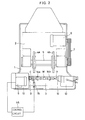
- the structure of the spindle head 10 is shown in detail in Fig. 3.
- the spindle head 10 includes a body 10a within which the workpiece 9 and a gear shaft 20 extend in parallel to one another and are rotatably supported by roller bearings 21, 21 and 22, 22, respectively.
- a spindle plate 24 is attached to the front end of the workpiece spindle 9 and includes an eccentric pin 23 extending axially of the spindle.
- a gear 25 is integrally formed on the rear end of the workpiece spindle 9 and meshed with a gear 26 which is, in turn, formed on the front end of the gear shaft 20.
- the rear end of the gear shaft 20 is coupled to the output shaft of the motor 8 through a joint 27.
- the workpiece spindle 9 includes an axially extending central bore.
- a ram support 10a is integral with the body 10a and has a front end extending into the central bore of the workpiece spindle 9 with a predetermined clearance left therebetween.
- a ram 28 extends into the ram support 10b and is slidable in a direction parallel to the axis of the workpiece spindle 9.
- a rod 37 is mounted within the body 10a and slidable in a direction parallel to the axis of the ram 28. The rear ends of the rod 37 and the ram 28 are interconnected together by a connecting plate 36. This allows the ram 28 to axially move, but restricts the ram 28 from rotating.
- a center 29 is fit in the front end of the ram 28.
- a rotary sleeve 32 is also rotatably mounted on the front end of the ram 28 through roller bearings 33 and 33.
- the rotary sleeve 32 includes a front flange 30 and a rear flange 31.
- the rear flange 31 has a groove 35 to receive a drive pin 23 which in turn, extends from the spindle plate 24.
- the front flange 30 has an opening 34 so as to prevent interference of the drive pin 23 with the rear flange 31 when the ram 28 is moved to its retreated position.
- a drive plate 52 is secured to the front of the front flange 30 and includes a central opening through which the front end of the center 29 extends.
- a screw shaft 39 is located within the spindle head 10 behind the ram 28.
- the screw shaft 39 is concentric with the ram 28 and is rotatably supported by a roller bearing 38.
- the screw shaft 39 includes at its front end a screw portion 39a for threaded engagement with a nut 40 which is, in turn, secured to the rear end of the ram 28.
- the screw shaft 39 has at its rear end a shaft portion 39b to which a gear 41 is mounted.
- a servo motor 42 is mounted to the spindle head 10 and has an output shaft to which a gear 43 is mounted for threaded engagement with the gear 41.
- a driving unit C is attached to the drive plate 52 and may be in the form of a hydraulically operated automatic dog clutch or in the form of a drive dog clutch such as shown in the drawing figures.
- the servo motor 42 is connected to a control circuit 44 and is controlled in response to a signal produced by axial position sensors 15a and 15b.
- the driving unit C is pivotably mounted to the front of the drive plate 52 and generally includes a floating member 54 and a pair of pawls 53 and 53.
- the floating member 54 includes a ring 56 having a central opening 55, and a pair of diametrically opposite arms 57 and 58 extending outwardly from the ring 56.
- the pawls 53 and 53 extend from the ring 56 in a diametrically opposite relation and are 90 ° out of phase with respect to the arms 57 and 58.
- Each pawl 53 has a front end extending into the central opening 55.
- the drive plate 52 has a bracket 59 on its front.
- the bracket 59 has a pivot pin about which the arm 57 of the floating member 54 is pivotable.
- the other arm 58 has an opening through which a bolt 62 extends.
- the bolt 62 is secured to the front of the drive plate 52 and has a head engaged with the front surface of the arm 58.
- Compression springs 58 and 58 are disposed between the front of the drive plate 52 and the arm 58 to bias the arm 58 so that the arm 58 may float relative to the drive plate 52.
- Guide elements 64 and 64 are attached to the drive plate 52 at opposite sides of the arm 58 so as to restrict displacement of the arm 58 in a circumferential direction.
- the tailstock spindle and the ram 28 are in their retreated position before abrasive action is initiated.
- the workpiece W is placed temporarily on the workpiece stand-by stations 14a and 14b by a loader or similar means. Thereafter, the workpiece spindle 9 is rotated at a low speed by the motor 8. Also, the servo motor 42 is driven to rotate the screw portion 39a of the screw shaft 39 through the gears 43 and 41. This causes the ram 28 with the nut 40 to slide forward within the workpiece spindle 9. With a slight delay, the tailstock spindle 12 is advanced. The workpiece W on the workpiece stand-by stations 14a and 14b is then supported by the centers 11 and 29.
- the floating member 54 may be moved toward the drive plate 52 against the action of the springs 63 and 63 in the event that the pawls 53 and 53 of the floating member 54 interferes with a portion of the workpiece W which is not bevelled.
- the pawls 53 and 53 are brought into engagement with a rotation transmission surface or bevel surface Wa which is formed on one end of the workpiece W.
- the axial position sensors 15a and 15a are moved forward to sense the axial position of the workpiece W.
- a signal indicative of the sensing is sent to the control circuit 44 so as to drive the servo motor 42 until the workpiece W is moved to a predetermined axial position.
- the ram 28 or the center 29 is advanced against the biasing force of the center 11 so as to hold the workpiece W in such a predetermined axial position.
- the workpiece W can thus be held in position without moving the table 3.
- the motor 8 is rotated at a higher speed to increase the speed of rotation of the workpiece W up to a predetermined level.
- the grinding wheels 4a and 4b are rotated by the motor 6 to initiate abrasive action.
- the driving unit which is engaged with the workpiece W is rotated in the following manner. Rotation of the motor 8 is transmitted to the driving unit C through the joint 27, the gear shaft 20, the gears 26 and 25, the workpiece spindle 9, the spindle plate 24, the drive pin 23, the rotary sleeve 32 and the drive plate 52. At this time, the drive pin 23 is always engaged with the groove 35 of the rear flange 31 of the rotary sleeve 32 regardless of whether the ram 28 is moved forwards or rearwards. The rotation can always be transmitted to the workpiece W.
- the wheel head 2 is retreated, and the motor 8 is stopped.
- the tailstock spindle 12 is moved to its retreated position.
- the servo motor is then rotated in a reverse direction so as to slide the ram 28 back to its retreated position through the gears 43 and 41, the screw portion 42a, and the nut 42.
- the workpiece W is released from the centers 11 and 12, placed on the workpiece stand-by stations 14a and 14b and then, moved away from the grinder by the loader.
Landscapes
- Engineering & Computer Science (AREA)
- Mechanical Engineering (AREA)
- Constituent Portions Of Griding Lathes, Driving, Sensing And Control (AREA)
- Turning (AREA)
Applications Claiming Priority (2)
| Application Number | Priority Date | Filing Date | Title |
|---|---|---|---|
| JP2110254A JPH048405A (ja) | 1990-04-27 | 1990-04-27 | 工作主軸装置 |
| JP110254/90 | 1990-04-27 |
Publications (2)
| Publication Number | Publication Date |
|---|---|
| EP0454093A2 true EP0454093A2 (de) | 1991-10-30 |
| EP0454093A3 EP0454093A3 (en) | 1992-04-08 |
Family
ID=14531025
Family Applications (1)
| Application Number | Title | Priority Date | Filing Date |
|---|---|---|---|
| EP19910106609 Ceased EP0454093A3 (en) | 1990-04-27 | 1991-04-24 | Spindle apparatus for supporting and rotating a workpiece |
Country Status (4)
| Country | Link |
|---|---|
| US (1) | US5303511A (de) |
| EP (1) | EP0454093A3 (de) |
| JP (1) | JPH048405A (de) |
| KR (1) | KR100206293B1 (de) |
Cited By (4)
| Publication number | Priority date | Publication date | Assignee | Title |
|---|---|---|---|---|
| DE19908247B4 (de) * | 1998-05-26 | 2004-04-15 | Bosch Automotive Systems Corp. | Schleifvorrichtung |
| EP1481762A1 (de) * | 2003-05-30 | 2004-12-01 | Toyoda Koki Kabushiki Kaisha | Wellenlagerung für die Schleifscheibe einer Schleifmaschine |
| DE102008026655B4 (de) * | 2007-06-13 | 2016-06-02 | Emag Holding Gmbh | Verfahren und Vorrichtung zum Schleifen von Nocken einer Nockenwelle |
| CN106944633A (zh) * | 2017-04-28 | 2017-07-14 | 盐城工业职业技术学院 | 伺服进给式尾架 |
Families Citing this family (10)
| Publication number | Priority date | Publication date | Assignee | Title |
|---|---|---|---|---|
| DE4327807C2 (de) * | 1993-08-18 | 1995-06-14 | Erwin Junker | Verfahren und Schleifmaschine zum Schleifen einer Kurbelwelle |
| US5733175A (en) | 1994-04-25 | 1998-03-31 | Leach; Michael A. | Polishing a workpiece using equal velocity at all points overlapping a polisher |
| US5607341A (en) | 1994-08-08 | 1997-03-04 | Leach; Michael A. | Method and structure for polishing a wafer during manufacture of integrated circuits |
| ES2117513B1 (es) * | 1994-10-18 | 1999-03-16 | Danobat | Mejoras en maquinas rectificadoras de alta velocidad para los alabes de rotores de motores de reaccion y similares. |
| US5643065A (en) * | 1996-04-12 | 1997-07-01 | Whitesel; Lowell E. | Indexing mechanism for rotatably mounted work holding spindle |
| DE69626318T2 (de) * | 1996-11-11 | 2003-12-11 | Nippei Toyama Corp | Vorrichtung zur phasenindexierung eines kurbelzapfens |
| US6390907B1 (en) * | 1998-02-09 | 2002-05-21 | Joel Kym Metzler | Machine tool and machine tool spindle and workpiece mounting-apparatus and grinding process |
| CN101264584B (zh) * | 2008-04-24 | 2011-01-26 | 昆山华辰机器制造有限公司 | 重型数控轧辊磨床高速、强力磨削动静压磨头 |
| CN101890661B (zh) * | 2009-05-21 | 2011-11-30 | 昆山华辰重机有限公司 | 数控轧辊磨床头架万能连接装置 |
| CN101913114A (zh) * | 2010-07-28 | 2010-12-15 | 上海机床厂有限公司 | 复合数控磨床高精度砂轮架分度机构 |
Citations (3)
| Publication number | Priority date | Publication date | Assignee | Title |
|---|---|---|---|---|
| US3653854A (en) * | 1969-09-29 | 1972-04-04 | Toyoda Machine Works Ltd | Digitally controlled grinding machines |
| DE2202805A1 (de) * | 1971-01-26 | 1972-08-17 | Litton Industries Inc | Werkzeugmaschine zur spanabhebenden Bearbeitung |
| DD277421A1 (de) * | 1988-11-30 | 1990-04-04 | Werkzeugmasch Okt Veb | Verfahren zum spannen von schlanken buchsenfoermigen werkstuecken zwischen spitzen beim aussenrundschleifen |
Family Cites Families (8)
| Publication number | Priority date | Publication date | Assignee | Title |
|---|---|---|---|---|
| US3142941A (en) * | 1962-10-03 | 1964-08-04 | Norton Co | Grinding machine |
| GB1158527A (en) * | 1967-05-30 | 1969-07-16 | Newall Eng | Improvements in Crankpin Grinders |
| GB1255746A (en) * | 1968-04-30 | 1971-12-01 | Toyoda Machine Works Ltd | A machine tool for grinding pins of a crank shaft |
| JPS4836396B1 (de) * | 1970-02-26 | 1973-11-05 | ||
| JPS4844915B1 (de) * | 1970-07-15 | 1973-12-27 | ||
| JPS55101369A (en) * | 1979-01-30 | 1980-08-02 | Toyoda Mach Works Ltd | Sizing device corrected at measuring position responsive to boring diameter |
| JPS5641925A (en) * | 1979-09-12 | 1981-04-18 | Nangoku Kiso Kk | Removal of steel wire for earth anchor work |
| US4454689A (en) * | 1981-09-09 | 1984-06-19 | Itm International Tool Machines, Inc. | Clamping arrangement |
-
1990
- 1990-04-27 JP JP2110254A patent/JPH048405A/ja active Pending
-
1991
- 1991-04-24 EP EP19910106609 patent/EP0454093A3/en not_active Ceased
- 1991-04-27 KR KR1019910006798A patent/KR100206293B1/ko not_active IP Right Cessation
-
1992
- 1992-10-15 US US07/962,006 patent/US5303511A/en not_active Expired - Lifetime
Patent Citations (3)
| Publication number | Priority date | Publication date | Assignee | Title |
|---|---|---|---|---|
| US3653854A (en) * | 1969-09-29 | 1972-04-04 | Toyoda Machine Works Ltd | Digitally controlled grinding machines |
| DE2202805A1 (de) * | 1971-01-26 | 1972-08-17 | Litton Industries Inc | Werkzeugmaschine zur spanabhebenden Bearbeitung |
| DD277421A1 (de) * | 1988-11-30 | 1990-04-04 | Werkzeugmasch Okt Veb | Verfahren zum spannen von schlanken buchsenfoermigen werkstuecken zwischen spitzen beim aussenrundschleifen |
Cited By (5)
| Publication number | Priority date | Publication date | Assignee | Title |
|---|---|---|---|---|
| DE19908247B4 (de) * | 1998-05-26 | 2004-04-15 | Bosch Automotive Systems Corp. | Schleifvorrichtung |
| EP1481762A1 (de) * | 2003-05-30 | 2004-12-01 | Toyoda Koki Kabushiki Kaisha | Wellenlagerung für die Schleifscheibe einer Schleifmaschine |
| US7086937B2 (en) | 2003-05-30 | 2006-08-08 | Toyoda Koki Kabushiki Kaisha | Wheel shaft supporting apparatus for grinding machine |
| DE102008026655B4 (de) * | 2007-06-13 | 2016-06-02 | Emag Holding Gmbh | Verfahren und Vorrichtung zum Schleifen von Nocken einer Nockenwelle |
| CN106944633A (zh) * | 2017-04-28 | 2017-07-14 | 盐城工业职业技术学院 | 伺服进给式尾架 |
Also Published As
| Publication number | Publication date |
|---|---|
| US5303511A (en) | 1994-04-19 |
| EP0454093A3 (en) | 1992-04-08 |
| KR100206293B1 (ko) | 1999-07-01 |
| JPH048405A (ja) | 1992-01-13 |
| KR910018125A (ko) | 1991-11-30 |
Similar Documents
| Publication | Publication Date | Title |
|---|---|---|
| US5303511A (en) | Spindle apparatus for supporting and rotating a workpiece | |
| US4625597A (en) | Screw driving apparatus | |
| US4175898A (en) | Tool changing apparatus | |
| EP1105239B1 (de) | Schnellrückzugvorschuss für werkzeugmaschine | |
| EP1245340A2 (de) | Handwerkzeug zum Aufpressen eines Maschinenteils auf eine Welle | |
| JP3206065B2 (ja) | 工作機械における切込み台の緊急後退装置 | |
| JP3082501B2 (ja) | 溶接トーチ用コンタクトチップの交換装置 | |
| US2099161A (en) | Grinding machine | |
| JP2631124B2 (ja) | 研削盤 | |
| US2161311A (en) | Grinding machine | |
| US1896752A (en) | Reversing mechanism for machine tools | |
| JPS6339379B2 (de) | ||
| US1665160A (en) | Automatic size-grinding machine | |
| JPS58211849A (ja) | 数値制御ブロ−チ研削盤 | |
| JP2521277Y2 (ja) | ワークレスト | |
| AU2773692A (en) | Drive positioning and coupling device | |
| JPH0513477Y2 (de) | ||
| SU1731584A1 (ru) | Загрузочное устройство | |
| JPS596995Y2 (ja) | ロ−タリドレツシング装置 | |
| JPH06143005A (ja) | 心押台 | |
| SU1625593A1 (ru) | Инструментальна бабка | |
| JP2796304B2 (ja) | 工作物駆動装置 | |
| JPS649140B2 (de) | ||
| JPH0144210Y2 (de) | ||
| SU1238892A1 (ru) | Задн бабка с электроприводом пиноли |
Legal Events
| Date | Code | Title | Description |
|---|---|---|---|
| PUAI | Public reference made under article 153(3) epc to a published international application that has entered the european phase |
Free format text: ORIGINAL CODE: 0009012 |
|
| AK | Designated contracting states |
Kind code of ref document: A2 Designated state(s): DE FR GB |
|
| RIN1 | Information on inventor provided before grant (corrected) |
Inventor name: MARUYAMA, TOSHIO Inventor name: NONOYAMA, MAKOTO Inventor name: TSUCHIYA, YUKIHARU Inventor name: YAMAGUCHI, MASAKAZU Inventor name: SANO, SHOICHI Inventor name: OISHI, KENZABURO |
|
| PUAL | Search report despatched |
Free format text: ORIGINAL CODE: 0009013 |
|
| AK | Designated contracting states |
Kind code of ref document: A3 Designated state(s): DE FR GB |
|
| 17P | Request for examination filed |
Effective date: 19920922 |
|
| 17Q | First examination report despatched |
Effective date: 19930614 |
|
| STAA | Information on the status of an ep patent application or granted ep patent |
Free format text: STATUS: THE APPLICATION HAS BEEN REFUSED |
|
| 18R | Application refused |
Effective date: 19940905 |