EP0453516B1 - Verfahren zum herstellen von siliciumkarbid - Google Patents
Verfahren zum herstellen von siliciumkarbid Download PDFInfo
- Publication number
- EP0453516B1 EP0453516B1 EP90903075A EP90903075A EP0453516B1 EP 0453516 B1 EP0453516 B1 EP 0453516B1 EP 90903075 A EP90903075 A EP 90903075A EP 90903075 A EP90903075 A EP 90903075A EP 0453516 B1 EP0453516 B1 EP 0453516B1
- Authority
- EP
- European Patent Office
- Prior art keywords
- silicon carbide
- silica
- carbon
- cooling
- reactive mixture
- Prior art date
- Legal status (The legal status is an assumption and is not a legal conclusion. Google has not performed a legal analysis and makes no representation as to the accuracy of the status listed.)
- Expired - Lifetime
Links
Images


Classifications
-
- C—CHEMISTRY; METALLURGY
- C01—INORGANIC CHEMISTRY
- C01B—NON-METALLIC ELEMENTS; COMPOUNDS THEREOF; METALLOIDS OR COMPOUNDS THEREOF NOT COVERED BY SUBCLASS C01C
- C01B32/00—Carbon; Compounds thereof
- C01B32/90—Carbides
- C01B32/914—Carbides of single elements
- C01B32/956—Silicon carbide
-
- B—PERFORMING OPERATIONS; TRANSPORTING
- B82—NANOTECHNOLOGY
- B82Y—SPECIFIC USES OR APPLICATIONS OF NANOSTRUCTURES; MEASUREMENT OR ANALYSIS OF NANOSTRUCTURES; MANUFACTURE OR TREATMENT OF NANOSTRUCTURES
- B82Y30/00—Nanotechnology for materials or surface science, e.g. nanocomposites
-
- B—PERFORMING OPERATIONS; TRANSPORTING
- B01—PHYSICAL OR CHEMICAL PROCESSES OR APPARATUS IN GENERAL
- B01J—CHEMICAL OR PHYSICAL PROCESSES, e.g. CATALYSIS OR COLLOID CHEMISTRY; THEIR RELEVANT APPARATUS
- B01J8/00—Chemical or physical processes in general, conducted in the presence of fluids and solid particles; Apparatus for such processes
- B01J8/0095—Chemical or physical processes in general, conducted in the presence of fluids and solid particles; Apparatus for such processes in which two different types of particles react with each other
-
- B—PERFORMING OPERATIONS; TRANSPORTING
- B01—PHYSICAL OR CHEMICAL PROCESSES OR APPARATUS IN GENERAL
- B01J—CHEMICAL OR PHYSICAL PROCESSES, e.g. CATALYSIS OR COLLOID CHEMISTRY; THEIR RELEVANT APPARATUS
- B01J8/00—Chemical or physical processes in general, conducted in the presence of fluids and solid particles; Apparatus for such processes
- B01J8/08—Chemical or physical processes in general, conducted in the presence of fluids and solid particles; Apparatus for such processes with moving particles
- B01J8/12—Chemical or physical processes in general, conducted in the presence of fluids and solid particles; Apparatus for such processes with moving particles moved by gravity in a downward flow
-
- C—CHEMISTRY; METALLURGY
- C01—INORGANIC CHEMISTRY
- C01B—NON-METALLIC ELEMENTS; COMPOUNDS THEREOF; METALLOIDS OR COMPOUNDS THEREOF NOT COVERED BY SUBCLASS C01C
- C01B32/00—Carbon; Compounds thereof
- C01B32/90—Carbides
- C01B32/914—Carbides of single elements
- C01B32/956—Silicon carbide
- C01B32/963—Preparation from compounds containing silicon
- C01B32/97—Preparation from SiO or SiO2
-
- C—CHEMISTRY; METALLURGY
- C01—INORGANIC CHEMISTRY
- C01P—INDEXING SCHEME RELATING TO STRUCTURAL AND PHYSICAL ASPECTS OF SOLID INORGANIC COMPOUNDS
- C01P2004/00—Particle morphology
- C01P2004/51—Particles with a specific particle size distribution
-
- C—CHEMISTRY; METALLURGY
- C01—INORGANIC CHEMISTRY
- C01P—INDEXING SCHEME RELATING TO STRUCTURAL AND PHYSICAL ASPECTS OF SOLID INORGANIC COMPOUNDS
- C01P2004/00—Particle morphology
- C01P2004/60—Particles characterised by their size
- C01P2004/61—Micrometer sized, i.e. from 1-100 micrometer
-
- C—CHEMISTRY; METALLURGY
- C01—INORGANIC CHEMISTRY
- C01P—INDEXING SCHEME RELATING TO STRUCTURAL AND PHYSICAL ASPECTS OF SOLID INORGANIC COMPOUNDS
- C01P2004/00—Particle morphology
- C01P2004/60—Particles characterised by their size
- C01P2004/62—Submicrometer sized, i.e. from 0.1-1 micrometer
-
- C—CHEMISTRY; METALLURGY
- C01—INORGANIC CHEMISTRY
- C01P—INDEXING SCHEME RELATING TO STRUCTURAL AND PHYSICAL ASPECTS OF SOLID INORGANIC COMPOUNDS
- C01P2004/00—Particle morphology
- C01P2004/60—Particles characterised by their size
- C01P2004/64—Nanometer sized, i.e. from 1-100 nanometer
-
- C—CHEMISTRY; METALLURGY
- C01—INORGANIC CHEMISTRY
- C01P—INDEXING SCHEME RELATING TO STRUCTURAL AND PHYSICAL ASPECTS OF SOLID INORGANIC COMPOUNDS
- C01P2006/00—Physical properties of inorganic compounds
- C01P2006/12—Surface area
-
- C—CHEMISTRY; METALLURGY
- C01—INORGANIC CHEMISTRY
- C01P—INDEXING SCHEME RELATING TO STRUCTURAL AND PHYSICAL ASPECTS OF SOLID INORGANIC COMPOUNDS
- C01P2006/00—Physical properties of inorganic compounds
- C01P2006/80—Compositional purity
Definitions
- the present invention relates to the field of ceramic powders. More Particularly, it relates to a process for producing silicon carbide ceramic powders.
- Silicon carbide is a ceramic material valued mainly for its high resistance to thermal stress and shock and its exceptional corrosion resistance in high temperature oxidizing environments. It has also found extensive use in the abrasives industry because of its hardness and wear resistance.
- silicon carbide exists in both an alpha and a beta form.
- the alpha phase is characterized as hexagonal, but exhibits many modifications or polytypes based upon stacking sequences in the layered structure.
- the beta phase in contrast, is cubic. In both of these structures every atom is tetrahedrally surrounded by four atoms of the other species, forming strong near-covalent bonds.
- Alpha silicon carbide is assumed to be the stable high temperature phase, and cubic beta silicon carbide transforms slowly to the alpha phase above about 1650°C. Various processes produce predominantly one or the other of these silicon carbide morphologies.
- a number of methods of manufacturing silicon carbide have been developed.
- a centrally mounted core of graphite and coke through which a large current can pass serves as a heater element. Maximum temperatures reached in this process approach 2700°C.
- the two-stage synthetic silica/carbon reduction process involves synthesis of a homogeneous, high-purity mixture of silica and carbon by a gas phase reaction, followed by synthesis of beta-type silicon carbide by a solid state reaction. This method is described as producing spherical, high-purity products having a narrow particle size distribution without aftertreatments.
- an 'ideal' ceramic powder for producing a high quality part should be of high purity and contain particles which are spherical, nonagglomerated and of a relatively uniform particle size ranging from about 0.1 to about 1.0 micrometer in diameter.
- the uniform and fine powders often densify at lower temperatures, thus representing cost savings in the long run and, because of their optimized packing capability, often producing significantly stronger and thus more reliable parts.
- silicon carbide production it has proven difficult to achieve the desired particle size and uniformity.
- Powders having a desirable size and purity level have also been successfully synthesized from radio frequency plasma-heated gases. See, e.g., US-A-4,266,977 to Steiger.
- US-A-3,346,338 to Latham, Jr. discloses the continuous production of finely-divided silicon carbide by passing a vapor of each reactant into one end of a furnace reaction zone and then recovering from the other end of the reaction zone a finely-divided carbide product.
- the laser- or plasma-heating of reactant gases is characterized by almost instantaneous heating rates of reactants, short reaction times (fractions of a second), minimal exposure to high temperatures, and almost instantaneous product cooling rates.
- the net result of the nearly instantaneous and uniform heating is submicrometer, uniformly sized ceramic particles.
- gas phase synthesized powders possess many desirable qualities, the powders are relatively expensive to produce because of the inherent low production rate and high cost of the required equipment and gaseous raw materials.
- the gas phase routes while academically interesting, may encounter serious limitations to commercial use.
- reactors have an inlet end, a reaction chamber, and an outlet end, and the reaction chamber is defined as the interior of an envelope of inert fluid which protects the inside tube wall from both the reactants and the products of reaction.
- silicon carbide is suggested as a possible product in, for example, US-A-3,933,434. However, the properties of the silicon carbide are neither described nor postulated.
- US-A-4,162,167, 4,292,276 and 4,529,575 to Enomoto also disclose an apparatus suitable for producing silicon carbide.
- the product consists mainly of beta-type crystals.
- the Enomoto apparatus is a vertical-type reaction vessel having an inlet for a starting material, a reaction zone and a closeable outlet for a product in this order. The closeable outlet allows extended reaction times, on the order of hours. When the process is carried out using excess carbon, the result is a product having an average particle size of greater than one micrometer. The particle size distribution is unspecified.
- US-A-4,368,181 to Suzuki et al describes a method of producing inexpensive beta-type silicon carbide by reacting silica having a particle size of less than 150 micrometers and carbon having a particle size of less than 60 micrometers at a temperature below 1650°C.
- the silicon monoxide formed during the reaction is then contacted again with unreacted carbon to increase the yield.
- the resulting product is described as consisting mainly of particles having a size of 0.04 to 0.08 micrometers, in the case of a reaction temperature of about 1450°C, and 0.1 to 0.3 micrometer, in the case of a reaction temperature of about 1600°C. Particle size distribution is unspecified.
- the present invention provides a process for preparing silicon carbide by carbothermal reduction comprising passing a particulate reactive mixture of a silica source and a carbon source through a heating zone such that substantially all of the particles of the reactive mixture are individually heated at a heating rate of at least 100°C/second to a sufficient temperature and for a sufficient length of time to form a product which, after burning out excess carbon and treatment with hydrofluoric acid to remove excess silica, is at least 80 weight percent silicon carbide crystals which have a size distribution such that at least 50 weight percent of the silicon carbide crystals is from 0.4 to 1.6 times the median crystal size.
- the present invention provides a process for preparing silicon carbide by carbothermal reduction which comprises passing a particulate reactive mixture of a silica source and a carbon source through a heating zone such that substantially all of the particles of the reactive mixture are individually heated at a heating rate of from 100°C per second to 100,000°C per second to a temperature within a range of from 1400°C to 2400°C for and maintained within that range for a time period of from 0.2 to 10 seconds to form a product which, after burning out excess carbon and treatment with hydrofluoric acid to remove excess silica, is at least 80 weight percent silicon carbide crystals which have a size distribution such that at least 50 weight percent of the silicon carbide crystals is from 0.4 to 1.6 times the median crystal size.
- the process of the present invention can be carried out to produce a composition which, after burning out excess carbon and treatment with hydrofluoric acid to remove excess silica, is at least 80 weight percent silicon carbide crystals such that at least 50 weight percent of the silicon carbide crystals is from 0.1 micrometer to 0.4 micrometer in diameter.
- Additional aspects of the present invention include a composition which, after burning out excess carbon and treatment with hydrofluoric acid to remove excess silica, is at least 80 weight percent silicon carbide crystals having a size distribution such that at least 80 weight percent of the silicon carbide crystals are from 0.1 micrometer to 0.4 micrometer in diameter and at least 50 percent of the silicon carbide crystals are from 0.4 to 1.6 times the median crystal size.
- a densified part produced from this composition is also encompassed.
- the present invention provides a process for preparing silicon carbide crystals by carbothermal reduction which comprises (1) passing a particulate reactive mixture of a silica source and a carbon Source into a reactor having (a) a reactant transport member, the reactant transport member having a wall defining a hollow conduit, the wall having a cooling means and being further characterized as having a concentric inner wall defining an inner annular space, the inner annular space having an inlet and being open at the bottom such that a gas can be flowed therethrough; (b) a reactor chamber, the reactor chamber having a wall defining a reaction zone, the chamber being in fluid communication with the reactant transport member; (c) a heating means, the heating means being suitable for heating the particulate reactive mixture in the reaction zone; and (d) a cooling chamber, the cooling chamber having a wall defining a cooling zone, the wall having a cooling means, the cooling chamber being in fluid communication with the reactor chamber; the temperatures of the reactant transport member, reactor chamber, and cooling chamber being independently
- the embodiments of the present invention thus provide a process for manufacturing fine silicon carbide ceramic crystals by rapid carbothermal reduction.
- the properties of the final product preferably include a narrow size distribution. Difficulties normally encountered with gaseous silicon monoxide losses during reaction are reduced.
- FIG. 1 is a plan view in cross-section of one embodiment of a reactor apparatus by which the present process can be carried out, illustrating with arrows the path of the reactants and product.
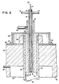
- FIG. 2 is a plan view in cross-section of the cooled reactant transport member of the reactor apparatus of FIG. 1.
- FIG. 3 is an X-ray diffraction pattern of silicon carbide powder prepared according to the method of one embodiment of the present invention.
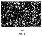
- FIG. 4 is a drawing of a scanning electron micrograph of silicon carbide powder prepared according to the method of one embodiment of the present invention.
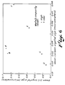
- FIG. 5 is a graphic portrayal contrasting reaction temperature and resultant silicon carbide crystal size for Examples 4-8.
- FIG. 6 is a graphic portrayal contrasting mean crystal size and purity of the carbon starting material with the resultant silicon carbide crystal size for Examples 4 and 11-15.
- the present invention is a process by which silicon carbide ceramic crystals can be prepared.
- the silicon carbide crystals of the present invention are produced by passing a particulate reactive mixture of a silica source and a carbon source through a heating zone such that substantially all of the particles of the reactive mixture are separately and individually heated at a very rapid rate. "Substantially all” herein means at least 75 percent of the particulate reactive mixture, and more preferably at least 95 weight percent.
- the silicon carbide ceramic powders produced thereby are preferably uniform and substantially pure, as described below.
- coefficient of variation refers to the ratio of a standard deviation to the mean value from which the standard deviation is measured. By way of illustration, a standard deviation of 0.6 and a mean value of 1 provide a coefficient of variation of 0.6.
- the starting silica source is preferably silica, and can be, for example, amorphous granular silica; a fumed silica such as that sold under the trade name CABOSIL* (*CABOSIL is a trademark of Cabot Corp.); a fine liquid dispersed colloid such as an aqueous colloidal silica; a silica gel; precipitated silica; a mixture thereof; or the like.
- the carbon source is desirably selected from the group consisting of forms of carbon, such as carbon black and acetylene carbon black; a hydrocarbon, defined as a compound containing carbon and hydrogen, including, for example, straight and branched chain alkyl compounds having 1 to 100 carbon atoms and cyclic compounds including alicyclic, aromatic, and heterocyclic compounds; a carbohydrate, including, for example, a complex or simple carbohydrate such as a sugar, for example, sucrose; a starch, for example, cornstarch; or a cellulose; another carbon-containing compound, such as vinylidene chloride polymer and other polymers capable of forming a carbon residue on thermal decomposition; or a mixture thereof.
- a hydrocarbon defined as a compound containing carbon and hydrogen, including, for example, straight and branched chain alkyl compounds having 1 to 100 carbon atoms and cyclic compounds including alicyclic, aromatic, and heterocyclic compounds
- a carbohydrate including, for example, a complex or simple
- the carbon sources listed above can be reacted as is, they are preferably calcined, either before or after admixture with the silica source, before the reactive mixture is introduced into the heating zone.
- the carbon source is preferably acetylene carbon black or some other form of carbon having a purity, in terms of metals, mean Martin's diameter and particle size distribution approximating that of acetylene carbon black.
- the carbon and silica starting sources together form a particulate reactive mixture. It is preferred that the silica source and carbon source are finely divided and intimately mixed. "Finely divided" means that it is preferred that the particle size of the particulate reactive mixture is less than 200 micrometers, more preferably less than 100 micrometers, and most preferably less than 50 micrometers.
- the degree of mixing of the particulate reactive mixture generally affects the kinetics of the reaction and therefore the quality of the final product. It is preferred that the mixture be as intimately mixed as possible, preferably by a method such as by spray drying a very fine dispersion of the silica source and the carbon source. Physical mixing is also possible, using methods such as, for example, ball milling. It is also possible to use a single source to supply both the silica and the carbon. One such intimate combined carbon and silica source is coked rice hulls.
- the carbon to silica mole ratio of the particulate reactive mixture is less than 3.5, preferably from 3.0 to less than 3.2, more preferably from 3.0 to 3.1, and most preferably 3.0. This ratio helps to reduce the presence of unreacted carbon in the product, and thus contributes to product purity.
- the mixture is rapidly reacted at a sufficient temperature and for a sufficient time to form a product aerosol by carbothermal reduction.
- This generally involves heating the reactive mixture in a heating zone.
- the rate of heating in part controls the characteristics of the final silicon carbide crystal product.
- a rapid heating rate is used to instigate a rapid reaction rate.
- the heating rate is greater than 100°C per second, more preferably greater than 500°C per second, and more preferably still, greater than 1000°C per second.
- the rate is still more preferably from 1,000°C to 100,000°C, and most preferably from 10,000°C per second to 100,000°C per second.
- the sufficient reaction temperature is desirably greater than 1400°C, preferably from 1600°C to 2400°C, more preferably from 1800°C to 2200°C and most preferably from 1800°C to 2100°C.
- the silicon carbide tends to be synthesized rapidly as part or all of a product aerosol.
- Sufficient time for the reaction is preferably on the order of less than two seconds, and more preferably less than one second.
- the aerosol can then be cooled to form a product as defined.
- the silicon carbide produced hereby preferably tends to be organized more predominantly in its beta-, rather than alpha-, form.
- This product is preferably uniform, preferably having silicon carbide crystals with diameters of less than 5 micrometers, more preferably less than 2 micrometers, still more preferably less than 1 micrometer, and most preferably from 0.1 micrometer to 0.4 micrometer.
- Preferably at least 25 percent by weight of the product crystals are less than one micrometer, more preferably at least 75 percent and most preferably 100 percent.
- the product, after burning out excess carbon and treatment with hydrofluoric acid to remove excess silica is also preferably at least 80 percent by weight silicon carbide, more preferably at least 90 percent by weight, and most preferably at least 95 percent by weight.
- Amounts of excess carbon, silica, silicon monoxide, or mixtures thereof, are preferably less than 20 percent by weight, more preferably less than 10 percent by weight and most preferably less than 5 percent by weight. It is also preferred that the product be stoichiometric silicon carbide.
- the size distribution of the silicon carbide crystals is preferably such that at least 50 percent are in the range from 0.4 times the median crystal size to 1.6 times the median crystal size. More preferably at least 80 percent are within this distribution range.
- Peter T. B. Shaffer et al. in "Production of Fine, High-Purity, Beta SiC Powder", Advances in Ceramics , Vol. 21, pages 257-263 (1987), disclose three post furnace treatments to reduce excess carbon and oxygen contents. They first crush the crude product then oxidize it for a few minutes at 750° C. or below to remove unreacted carbon. They then deagglomerate the oxidized SiC powder using an attrition mill with steel media and an inert halocarbon. After completing the milling and allowing the halocarbon to evaporate, the resulting powder is washed twice with 10% hydrochloric acid, twice with concentrated hydrofluoric acid and once with ethanol before it is dried to yield the final product.
- the teachings of this reference are incorporated herein by reference.
- Control of mean crystal size and size distribution of the resultant silicon carbide crystals is very beneficial. Such control allows one to tailor the green density of a silicon carbide part before it is fired. Since green density influences, in turn, part shrinkage and fired density of the part, such control Significantly influences the ability to fabricate quality parts.
- the carbon source is preferably acetylene carbon black or another carbon form of similar purity, size and size distribution, e.g., with a mean Martin's diameter of less than one micrometer, more preferably within a range of 0.02 to 0.08 micrometers, both ends included, and with substantially all of the carbon having a Martin's diameter of less than 0.4 micrometer;
- the reaction temperature is desirably within a range of 1800° C. to 2200° C., preferably 1800° C. to 2100° C.; and the reaction time is suitably within a range of 0.2 to ten seconds, desirably within a range of 0.2 to five seconds and preferably within a range of 0.2 to three seconds.
- silicon carbide crystals prepared in accordance with the present invention have a mean Martin's diameter of less than 0.25 micrometer, a coefficient of variation of 0.6 or less, and an unmilled BET surface area of less than or equal to 30 m2/g, beneficially less than 18 m2/g and desirably from 12 to 18 m2/g.
- the mean Martin's diameter is desirably within a range of 0.06 to 0.18 micrometers, both ends included.
- the coefficient of variation is desirably within a range of 0.2 to 0.6 inclusive.
- Particularly preferred silicon carbide crystals also have a maximum Martin's diameter of 0.5 micrometer.
- the silicon carbide product of the present invention can preferably be prepared in a reactor apparatus having a heating zone and, more preferably, also a cooling zone.
- a reactor apparatus having a heating zone and, more preferably, also a cooling zone.
- This reactor apparatus is preferably a vertical-type reactor in which starting reactants can be rapidly heated to react them to form a reaction product which is then rapidly cooled and continuously removed therefrom.
- the reactor's design helps to eliminate problems which can occur near either the inlet or outlet ends. At these locations silica or silicon monoxide may contact the reactor internal surfaces. Since the temperature may be such that gaseous silicon monoxide is cooled and condenses, plugging can result from improper design, operation or both.
- the reactant transport member 6 comprises a wall defining a conduit for injecting reactants.
- This member 6 can be cylindrical, rectangular, or of other effective configuration.
- the member 6 is preferably constructed of copper, which exhibits the desired thermal conductivity and which allows for placement of at least its tip directly within the radiating reactor chamber 16. Preferably a short length of it can be placed directly within the radiating reactor chamber 16. Other conductive materials can also be used.
- the reactant transport member 6 is cooled, preferably with cold water flowing through a cooling jacket 8.
- the jacket is preferably baffled by baffle 10 with coolant flowing in through a coolant inlet 12 and out through a coolant outlet 14. Other suitable heat transfer systems can also be used.
- This reactant transport member 6 is arranged in fluid connection with the reactor chamber 16 such that near the transport member exit 19 there is a gas-flow space 20 defined along the perimeter of the cooled member, i.e., outside of the cooling jacket or other heat transfer system, and in communication with the reactor chamber 16.
- a gas-flow space 20 defined along the perimeter of the cooled member, i.e., outside of the cooling jacket or other heat transfer system, and in communication with the reactor chamber 16.
- the gas-flow space 20 is at some point in fluid communication with a sweep gas inlet 22, and is preferably open along its entire lower limit to allow sweep gas to exit into the reactor chamber 16.
- the gas-flow space 20 can preferably describe an annular region.
- the sweep gas inlet 22 can be constructed such that it is part of a support sleeve 25, which can be secured to outer shell 30 by bolts or other fasteners 27 at one end and which is preferably sealed by gasket or other sealing means 31 at the opposite end to help to ensure a gas-tight seal.
- the reactant transport member 6 further comprises an inlet opening 24.
- Reactor chamber 16 comprises a reactor wall 26 which is preferably constructed of graphite. Other refractory materials, such as, for example, other carbonaceous materials, can also be used.
- the reactor wall 26 is preferably supported by being connected to an internally screw-threaded bushing 29. This wall defines a reaction zone 28.
- Preferably concentric with reactor wall 26 is an outer shell 30.
- the outer shell 30 serves to shield the environment from the extremely high temperatures, preferably above 1400°C, which will be used in the reaction zone 28.
- the outer shell 30 preferably encloses a layer 32 of an insulating material, and is cooled using an appropriate means such as a water-cooling system.
- there is also a gas plenum region 34 disposed between the reactor wall 26 and the outer shell 30. This gas plenum region 34 is also in fluid communication with plenum gas inlet 36 and plenum gas outlet 38.
- the heating means 40 is a group of heating elements or electrodes located outside of the reaction zone.
- the heating means is suitable to heat the reactor wall 26, which can then radiate heat to raise the temperature of the contents of the reaction zone 28 to a desired reaction temperature
- the electrodes are preferably graphite and can be disposed vertically or horizontally. They can be of any shape, including, for example, hairpin and linear rod configurations. Direct or inductive heating of the reactor wall 26 by electrical resistance using an appropriate source of electricity is also possible.
- the heating means be disposed such that, in particular, the area of the reaction zone 28 directly proximate to the reactant transport member 6 can be maintained at a desired reaction temperature. This helps to ensure very rapid radiant heating of the reactants as they pass from the reactant transport member 6 into the reaction zone 28.
- the cooling chamber 42 comprises a cooling zone 44 which communicates with the reaction zone 28 by means of a cooling inlet 46.
- the cooling chamber 42 is preferably configured such that its diameter is larger than the diameter of a cooling inlet 46 disposed between the reaction zone 28 and the cooling zone 44. Diameter is defined to mean the greatest distance across a given cross-sectional area, and thus can refer to the greatest distance across a circular or elliptical cross-section, or the diagonal length of a rectangular cross-section. It is preferred that the cooling inlet 46 is of approximately the same diameter as the reaction chamber 16; however, it is also possible for the cooling inlet to be constricted relative to the reaction chamber 16.
- the cooling chamber preferably has a diameter that is larger than the diameter of the reactor chamber 16, and where there is a constriction the cooling chamber 42 preferably has a diameter as defined that is larger than the diameter of the cooling inlet 46.
- the cooling chamber 42 can be essentially cylindrical, elliptical, rectangular, or of other effective configuration. It comprises a cooling wall 48 which allows for maintenance of temperatures below 350°C, Preferably below 100°C and most preferably below 50°C in the cooling zone.
- a cooling wall 48 which allows for maintenance of temperatures below 350°C, Preferably below 100°C and most preferably below 50°C in the cooling zone.
- an appropriate water-cooling jacket or other cooling system is effective and can be incorporated into the apparatus, or applied externally, as desired, with coolant flowing into coolant area 49 through a coolant inlet 50 and out through a coolant outlet 52.
- other cooling means known to those skilled in the art, including, for example, cool gas quenching systems.
- the selected means thus is any means suitable to allow for very rapid cooling of the product powder as it exits from the reaction chamber.
- the apparatus of the embodiment of FIG. 1 has an exit 54 at its opposite extreme from the reactant transport member 6.
- the exit 54 can preferably be in fluid communication with a collection device (not shown), such as a cyclone or bag filter, in which the final product of the reaction can be collected for further processing as desired.
- the method in which the apparatus described above can be used for preparing silicon carbide including but not limited to the apparatus described in the embodiment illustrated by FIG. 1 and FIG. 2, will be described in detail.
- the reactants used for illustrative purposes herein will be silica and carbon black.
- the particulate reactive mixture of silica and carbon black is preferably first prepared.
- This reactive mixture can be prepared by physically blending the solid reactants or by other means such as drying a liquid solution containing the reactants on the surface of a rotating drum or within a dryer.
- the reactive mixture particles preferably have a diameter of less than 150 micrometers, more preferably less than 100 micrometers, and most preferably less than 50 micrometers. This is because larger particles or aggregates will tend to fall through the reaction zone having only their surfaces reacted. Milling or grinding of the reactive mixture particles may be necessary in order to achieve desired particle size. The desired particle size can thus be attained with the use of jet mills, ball mills, attrition mills, hammer mills, or any other suitable device.
- Dispersers such as opposing jets, centrifugal fans and the like can also be employed to break up any agglomerates present in the particulate reactive mixture prior to its introduction into the reaction zone. It is also possible to directly spray dry a liquid solution, slurry or gel of the reactants in order to achieve the desired reactive mixture particle size.
- the spray dried solution can incorporate water or, in some cases, an appropriate organic material as a Solvent.
- a binder can be included if desired to aid in forming the reactive mixture.
- the reactive mixture is preferably introduced using a feeder system that produces as uniform a flow of the mixture as possible.
- a feeder system that produces as uniform a flow of the mixture as possible.
- Various applicable feeders such as twin screw feeders, star valves, slow speed screw feeders, venturi feeders, and the like, as well as modifications thereof, will be known to the skilled artisan.
- the feeder is desirably a twin screw feeder.
- the particles of the reactive mixture are preferably entrained in a gas, which can be either an inert gas, such as argon or another noble gas, or a gas which is compatible with the desired reaction, i.e., which either serves as a reactant or is the same as that produced as a reaction by-product.
- a gas which can be either an inert gas, such as argon or another noble gas, or a gas which is compatible with the desired reaction, i.e., which either serves as a reactant or is the same as that produced as a reaction by-product.
- argon, helium, nitrogen or hydrogen can preferably be used, with argon being more preferred Hydrogen may be particularly compatible since water in the reactive mixture will react with the carbon to produce carbon monoxide and hydrogen.
- the entrained particles are then introduced into the reactant transport member 6 via the inlet opening 24.
- the gas serves as a carrier to move the particles through the apparatus.
- the apparatus is positioned vertically, with the reactant transport member 6 at the top and the cooling chamber 42 at the bottom. In this orientation gravity also assists in moving the particles.
- the apparatus can be used in alternative positions, e.g., horizontally, as long as there is sufficient entrainment gas velocity to ensure continuous movement of the particles through the reactor at a sufficient rate.
- a sweep gas which is again preferably either an inert gas or a reaction-compatible gas, is passed through gas-flow space 20, where it tends to inhibit contact of any entrained solid, liquid or vapor portions of the reactive mixture with upper reactor chamber surface 18, which is the surface of plug 23 and any surfaces near the juncture between the reactant transport member outlet 19 and the reaction zone 28.
- These surfaces may be at a temperature below the reaction temperature, which is preferably at least 1400°C.
- silica is used as a reactant it could result in the formation of gaseous silicon monoxide in the temperature range above 1150°C, which, without the gas-flow space, could tend to condense and cause plugging at the cooler sites. This could, in turn, result in the formation of large agglomerated particles which could pass through the reaction zone and, upon collection as product, contain incompletely converted inner cores of reactant.
- the reactor design described herein circumvents or reduces this problem.
- the sweep gas continues out into the reaction zone 28, where it mixes with the entraining gas and reactant particles.
- the temperature in the reactant transport member 6 is preferably less than 350°C, more preferably less than 100°C, and most preferably less than 50°C.
- a gas is introduced into the gas plenum region 34 exterior of the reactor chamber 16. This gas can preferably be independently selected from the same selection of gases as the sweep gas. For example, in some cases it may be desirable to use nitrogen as the purge gas, whether or not it is also used as the sweep or entrainment gas, because of nitrogen's electrical properties.
- the reaction zone temperature is much hotter, desirably above 1400°C, preferably above 1600°C, still more preferably above 1800°C, more preferably from 1800°C to 2200°C and most preferably from 1800°C to 2100°C. As the particles of the silica source and the carbon source enter the hotter reaction zone, they are rapidly heated and reacted.
- the reactants or components of the reactive mixture e.g., silica and carbon
- the reaction zone is preferably elongated, and the reactant particle size and constituent intimacy, entraining gas flow rate, length of the reaction zone, and reaction zone temperature are preferably suitable for ensuring completion of the desired reaction.
- the entraining gas and any product aerosol i.e., product particles and any volatile materials such as gaseous silicon monoxide and gaseous carbon monoxide, are then introduced directly into the cooling chamber 42, which is preferably expanded, as described above.
- This expanded cooling chamber 42 is preferably maintained at a temperature below 350°C to rapidly cool the product.
- the cooling chamber 42 is more preferably below 100°C, and most preferably below 50°C.
- the reaction Upon reaching the cooling zone 44, the reaction is effectively stopped.
- the cooling chamber's preferred expanded configuration, as described above, in which the cooling chamber diameter is larger than the diameter of the cooling inlet and, preferably, also larger than the diameter of the reactor or reaction chamber, serves two main purposes.
- unreacted liquid reactants e.g., silicon monoxide
- the product can preferably be collected after it has passed through the cooling zone 44.
- a cyclone or other collection means e.g., a filter arrangement of some type, can be used.
- the resulting silicon carbide powder preferably shows substantial uniformity of constituent crystal shape and diameter.
- the powder particularly after burning out excess or unreacted carbon and treatment with hydrofluoric acid to remove excess silica, preferably comprises at least 25 percent by weight beta-type silicon carbide crystals, more preferably at least 75 percent, and most preferably at least 90 percent. At least 25 percent, more preferably at least 75 percent, and most preferably at least 90 percent of these crystals are preferably in the range of less than 5 micrometers, more preferably less than 2 micrometers, still more preferably less than 1 micrometer in size. It is still more preferred that at least 50 percent are in the size range from 0.1 to 0.4 micrometers, and it is most preferred that at least 80 percent are in this size range.
- a particularly preferred silicon carbide powder contains, after burning out excess or unreacted carbon and treatment with hydrofluoric acid to remove excess silica, at least 80 weight percent of silicon carbide crystals which have a mean Martin's diameter of less than 0.25 micrometer and a size distribution sufficient to provide a coefficient of variation of 0.6 or less.
- the mean Martin's diameter is most preferably within a range of 0.06 to 0.18 micrometer.
- the coefficient of variation is most preferably within a range of 0.1 to 0.6.
- This final product powder can be made very pure, and is preferably at least 80 weight percent stoichiometric silicon carbide, more preferably at least 90 weight percent, and most preferably at least 95 percent.
- It may, in some instances, contain small amounts of unreacted carbon, which can be burned out of the product in oxygen, air, steam or carbon dioxide. It may also contain very small amounts of unreacted silica, which can be dissolved with hydrofluoric acid and then removed by washing. The procedures for these aftertreatments are described hereinabove.
- Densification methods can be used to densify or consolidate the ceramic powders of one embodiment of the present invention to form the densified parts of another embodiment.
- the uniformity of crystal size and configuration attainable through preparing silicon carbide powder by the method of the present invention can enable production of a fine-grained product of theoretical or near-theoretical density with minimal void spaces.
- the void spaces can, in turn, have a detrimental effect on various physical properties of the densified products, such as strength. Because extensive milling operations of the powder prior to densification are not needed, substantial cost and time reductions can be achieved.
- the purity level of the powder as produced, e.g., without milling also reduces potential degradation of properties caused by Significant impurity levels.
- reaction variables include: (1) the temperatures of the reactant transport member, reaction zone, and cooling zone; (2) the flow rate of the sweep and entrainment gases and therefore of the reactants; (3) the reaction zone cross-sectional dimension or dimensions and length; (4) the relationship of the diameters of the cooling chamber and the cooling inlet; and (5) the temperature of sweep, entrainment and by-product gases within the reaction chamber.
- the quantity of by-product gases generated in the reaction should, in some cases, be taken into account in making these adjustments, since it will affect flow rates.
- the residence time is preferably from 0.2 to 10 seconds, but longer or shorter times can also be employed.
- Example 1 Silicon carbide prepared at 1900°C under argon:
- Reactive mixture preparation About 3.60 kg of acetylene carbon black and 16.95 kg of a colloidal silica slurry, at a solids concentration of 35.37 percent and a pH of 3, are admixed with about 0.36 liter of TRITON X-100* dispersant (*TRITON X-100 is a trademark of Rohm & Haas Co.), which is alkyl phenoxy polyethoxy ethanol, and 45.5 liters of deionized water. Mixing is done in a plastic-lined container using a stainless steel impeller. The slurry, having a stoichiometric molar carbon to silica ratio of 3.0, is mixed under high agitation for about 3 hours.
- TRITON X-100 is a trademark of Rohm & Haas Co.
- the resulting mixture is then spray-dried in a spray dryer unit.
- the slurry is fed into the spray dryer at a rate of from 40 to 50 kg/hr under a drying air stream of about 505 kg/hr.
- Inlet and outlet temperatures are kept at 300°C and 110°C, respectively, and the dried powder is collected in the drying chamber and a downstream cyclone.
- the product obtained is in the form of a black powder having approximately 4 percent moisture content.
- This material shows a median particle size of approximately 25 micrometers and is very free-flowing.
- About 90 percent of this reactive mixture powder has a particle size of less than 48 micrometers; about 50 percent is less than 23 micrometers; and about 10 percent is less than 8.8 micrometers.
- Examination of the powder by a scanning electron microscope shows a spherical morphology with fine silica particles being dispersed in a carbon matrix.
- the spray dried carbon/silica reactive mixture is dehydrated in a tray oven at 400°C for 12 hours.
- a thermogravimetric analysis shows the final product to be an intimate and finely divided reactive mixture composition containing 0.3 weight percent hydrated water.
- Some of the dehydrated reactive mixture is loaded into a feed hopper and purged with argon gas for 30 minutes.
- a 4.5 inch inside diameter x 3.3 foot long (11.43 cm inside diameter x 1 m long) vertical graphite tube furnace is brought to a temperature of 1900°C as measured via an optical pyrometer.
- the intimate and finely divided particulate reactive mixture is fed into the vertical furnace via a reactant transport member at the rate of 0.33 kg/hour.
- Argon flows through the reactant transport member at the rate of 21.52 standard liters per minute, thus sweeping the particulate reactive mixture with it.
- product is collected from a downstream baghouse and analyzed chemically.
- Carbon content is determined via a combustion analysis as 29.32 weight percent carbon. There is also present 3.68 weight percent oxygen. The product is therefore calculated to be at least 91 weight percent silicon carbide, assuming that all oxygen present is in the form of unreacted silicon dioxide, or at least 87 percent, assuming all oxygen present is in the form of silicon monoxide.
- An X-ray diffraction pattern of the product indicates that the powder is at least 90 percent by weight primarily beta silicon carbide with a minor amount of alpha silicon carbide present. (See FIG. 3.) No free carbon or silica is detected in the X-ray pattern.
- a scanning electron micrograph indicates that the powder is comprised primarily of uniform crystals of approximately 0.1 to 0.5 micrometer diameter.
- Individual crystals from a representative transmission electron micrograph (TEM) are counted and a median crystal size of 0.19 micrometer with 0.05 micrometer standard deviation is determined, i.e., more than 50 percent of the crystals fall within a range of from 0.14 to 0.24 micrometers, which is also a range from 0.7 times the median crystals size to 1.3 times the median crystal size. More than 80 percent fall within a range from 0.1 to 0.3 micrometers.
- the aggregate surface area, without milling, is about 18 m2/g as determined by Brunauer-Emmett-Teller (BET) analysis, which is a nitrogen physisorption analysis.
- BET Brunauer-Emmett-Teller
- the chemical composition of individual crystals is determined by an electron diffraction microprobe to be silicon carbide.
- Example 2 Silicon carbide prepared at 2000°C under argon:
- a particulate reactive mixture prepared as described in Example 1, is loaded into a feed hopper and purged with argon gas for 30 minutes.
- a 4.5 inch inside diameter x 3.3 foot long (11.43 cm inside diameter x 1 m long) vertical graphite tube furnace is brought to a temperature of 2000°C as measured via an optical pyrometer.
- the intimate and finely divided particulate reactive mixture is fed into the vertical furnace via a water-cooled reactant transport member at a rate of 0.33 kg/hour.
- Argon flows through the reactant transport member at a rate of 21.52 standard liters per minute, sweeping the particulate reactive mixture with it.
- product is collected from a downstream baghouse and analyzed chemically.
- Carbon content is determined via a combustion analysis as 29.50 weight percent carbon. There is also present 2.94 weight percent oxygen. The product is therefore calculated to be at least 93 weight percent silicon carbide, assuming that all oxygen present is in the form of unreacted silicon dioxide, or at least 89 weight percent, assuming all oxygen present is in the form of silicon monoxide.
- An X-ray diffraction pattern of the product indicates that the powder is at least 75 percent by weight beta silicon carbide with some alpha silicon carbide present. No free carbon or silica is detected in the X-ray pattern.
- a scanning electron micrograph indicates that the powder is comprised primarily of uniform, crystals of 0.1 to 0.5 micrometer diameter. Individual crystals from a representative transmission electron micrograph are counted and a median crystal size of 0.27 micrometer with 0.14 micrometer standard deviation is determined, i.e., at least 50 percent by weight fall within a range of from 0.1 to 0.4 micrometers, and also within a range from 0.4 times the median particle size to 1.5 times the median particle size.
- the chemical composition of individual crystals is determined by an electron diffraction microprobe to be silicon carbide.
- a reactive mixture prepared as described in Example 1, is loaded into a feed hopper and purged with argon gas for 30 minutes.
- a 4.5 inch inside diameter x 3.3 foot long (11.43 cm inside diameter x 1 m long) vertical graphite tube furnace is brought to a temperature of 2100°C as measured via an optical pyrometer.
- the intimate and finely divided particulate reactive mixture is fed into the vertical furnace via a water-cooled reactant transport member at a rate of 0.33 kg/hour.
- Argon flows through the reactant transport member at the rate of 21.52 standard liters per minute, sweeping the particulate reactive mixture with it.
- product is collected from a downstream baghouse and analyzed chemically.
- Carbon content is determined via a combustion analysis as 31.74 weight percent carbon. There is also present 2.87 weight percent oxygen. The product is therefore calculated to be at least 89 weight percent silicon carbide, assuming that all oxygen present is in the form of unreacted silicon dioxide, or at least 86 weight percent, assuming that all oxygen present is in the form of silicon monoxide.
- An X-ray diffraction pattern of the product indicates that the powder is primarily beta silicon carbide with some alpha silicon carbide present. No free carbon or silica is detected in the X-ray pattern.
- a scanning electron micrograph indicates that the powder is comprised primarily of uniform, approximately 0.1 to 0.7 micrometer diameter crystals. Individual crystals from a representative TEM are counted and a median crystal size of 0.40 micrometer with 0.19 micrometer standard deviation is determined, i.e., more than 50 percent of the crystals fall within a range of from 0.21 to 0.59 micrometers, and also within a range of from 0.5 to 1.5 times the median particle size.
- the chemical composition of individual crystals is determined by an electron diffraction microprobe to be silicon carbide.
- Example 4 Silicon carbide prepared at 2100° C under argon:
- Reactive Mixture Preparation About 1.8 liters of the TRITON X-100* dispersant used in Example 1, 450 milliliters (ml) of ammonium hydroxide and 350 ml of a silicone compound commercially available from Dow Corning Corporation under the trade designation ANTIFOAM BTM are admixed with 288 pounds (130.8 kg) of deionized water in a 55 gallon (208.2 liter) plastic drum. After mixing for ten minutes with a stainless steel impeller as in Example 1, 25 pounds (11.4 kg) of acetylene carbon black are added, while mixing continues, using a DISPERSATOR* 3000 (*DISPERSATOR* 3000 is a trademark of Premier Mill) to form a slurry.
- DISPERSATOR* 3000 (*DISPERSATOR* 3000 is a trademark of Premier Mill)
- the slurry is mixed under high agitation for about one hour or until no visible agglomerates are apparent.
- 95.6 pounds (43.4 kg) of colloidal silica commercially available from P. Q. Corporation under the trade designation NYACOLTM 2040NH4 (analyzed as 37.93 weight percent 20 nm silica in water) is added to the slurry which is then mixed under high agitation for an additional hour.
- the resulting slurry is spray dried as in Example 1, save for increasing the outlet temperature to 130° C., to provide a spray dried powder.
- the spray dried powder is collected and dehydrated in an inert gas oven (with flowing gaseous nitrogen) for ten hours at 400° C. to remove the dispersant and chemically bound water associated with the colloidal silica.
- the dehydrated powder has an average particle size, as determined using a single powder counter commercially available from Pacific Scientific under the trade designation HIAC, of about 43 micrometers.
- Carbon content, determined as in Example 1, is 39.2 weight percent indicating a carbon to silica molar ratio of 3.2.
- a six inch inside diameter x eleven foot long (15.2 cm inside diameter x 3.4 m long) vertical graphite tube furnace is brought to a temperature of 2100° C. as measured by optical pyrometers viewing the outside wall of the reaction chamber.
- the dehydrated powder is fed into the vertical furnace at a rate of 0.2 pound/minute (0.09 kg/minute) via a twin screw loss-in-weight feeder through a water cooled cold finger maintained at a temperature of 22° C.
- Argon gas flows into the top of the furnace at a rate of four SCFM (113.3 standard liters per minute) (three SCFM entrainment gas and one SCFM sweep gas), thus sweeping the dehydrated powder with it.
- a sample of product powder is collected after reaching a steady state condition via an in-line sampling device below the furnace's cooling zone.
- An X-ray diffraction pattern of the product indicates that the silicon carbide content of the powder is at least 90 weight percent beta silicon carbide with a minor amount of alpha silicon carbide present.
- Chemical analysis as in Example 1 shows a carbon content of 31.7 weight percent and an oxygen content of 7.0 weight percent, thereby indicating a silica conversion of about 89.9 percent.
- the remainder of the product powder is collected by a device such as a cyclone or a bag filter.
- a sample of the product powder is placed in a quartz boat within a tube furnace. Air is passed over the boat and the tube furnace temperature is raised to a temperature of 630° C. and maintained at that temperature for sixteen hours to burn out unreacted residual carbon. The furnace is then cooled and the boat and treated powder are removed from the furnace.
- the treated powder is placed in a graphite crucible within a high temperature graphite furnace.
- Argon gas is passed over the crucible and the furnace temperature is raised to a temperature of 1450° C. and maintained at that temperature for four and one-half hours to remove unreacted or residual silicon oxides from the product powder (SiC).
- the treated SiC powder has a BET surface area, without milling, of 13.1 m2/g.
- Some of the treated SiC powder is sonicated to disperse the crystals and analyzed by transmission electron microscopy.
- Martin's diameter is measured for 529 particles and the particle size distribution is determined from digitized statistical analysis of the diameters.
- the mean Martin's diameter is 0.121 micrometer with a standard deviation of 0.046 micrometer.
- the Martin's diameter ranges from 0.02 to 0.32 micrometer. This corresponds to a coefficient of variation of 0.38.
- Example 4 The procedure of Example 4 is replicated at various temperatures. The temperatures and analytical results for Examples 5-8 are shown together with their counterparts from Example 4 in Table I.
- Fig. 5 graphically displays the relationship between temperature and mean Martin's diameter of the resultant silicon carbide crystals.
- the silicon carbide contents shown in Table I are, as in Example 4, based upon the assumption that all oxygen present is in the form of silicon monoxide.
- Table I Chemical and Physical Analysis of SiC Powders Synthesized from Acetylene Carbon Containing Precursors Temp. (°C) 1800 1900 2000 2100 2200 Reaction Time (seconds) 3.3 2.7 2.6 2.5 2.3 Silica Source Size (»m) 0.02 0.02 0.02 0.02 0.02 0.02 0.02 Raw SiC Product Wt.
- Example 9 Silicon Carbide Prepared at 1900° C. With Increased Residence Time
- Example 6 The procedures of Example 6 are duplicated save for removing the product powder from the collection device and passing through the vertical furnace a second time before post treatment and analysis.
- the mean Martin's diameter is 0.121 micrometer with a standard deviation of 0.049 micrometer and a range of 0.03 to 0.29 micrometer. This corresponds to a coefficient of variation of 0.4.
- Example 6 A comparison of the mean Martin's diameter of the silicon carbide crystals of Example 6 with that of Example 9 shows an increase in diameter of about 42 percent due to increasing the reaction or residence time from 2.7 seconds (Example 6) to 6.5 seconds (Example 9). This data suggests that reaction time is also a suitable parameter for tailoring the ultimate silicon carbide crystal size. Similar results are expected with other reactive mixtures and process variations, all of which are described herein.
- Example 10 Silicon Carbide Prepared at 2100° C. With Increased Silica Particle Size
- Example 4 The procedure of Example 4 is modified by preparing a silica slurry in a second 55 gallon (208.2 liter) plastic drum. The silica slurry is added to the carbon black slurry in place of the colloidal silica used in Example 4.
- the resultant silicon carbide product is post treated and analyzed as in Example 4. Chemical analysis of the post treated powder shows a carbon content of 29.5 weight percent and an oxygen content of 1.0 weight percent, indicating that the product has a silicon carbide content of greater than 96.7 weight percent, assuming all oxygen present is in the form of silicon monoxide.
- the mean Martin's diameter (480 particles) is 0.133 micrometer with a standard deviation of 0.045 micrometer and a range of 0.04 to 0.33 micrometer. The coefficient of variation is 0.34.
- the BET surface area is 6.9 m2/g.
- Example 10 shows that silica particle size does not influence resultant silicon carbide crystal size to the same degree as reaction time and temperature. A greater than fifty-fold increase in silica particle size (Example 4 versus Example 10) still allows production of satisfactory silicon carbide. If a greater BET surface area is needed, varying other parameters, particularly reaction temperature, should bring about the desired result. Similar results are expected with other reactive mixtures and process variations, all of which are described herein.
- Example 4 The procedure of Example 4 is replicated using other sources of carbon.
- the sources of carbon are summarized in Table II.
- the chemical impurity levels and certain physical properties for the sources of carbon are summarized in Table III.
- the oxygen and carbon contents are determined by combustion analysis using, respectively, a LECO TC-436 analyzer and a LECO IR-412 analyzer.
- Certain physical properties of silicon carbide crystals prepared with the various carbon sources are tabulated in Table IV and graphically portrayed in Fig. 6.
- the silicon carbide contents shown in Table IV are, as in the preceding examples, based upon the assumption that all oxygen present is in the form of silicon monoxide.
- Table II Carbon Sources Legend Source A Commercially available from Cabot Corp. under the trade designation ELFTEXTM 8 B Commercially available from Cabot Corp.
- a starting carbon with both high purity and small particle size (Example 4) provides silicon carbide crystals with a greater BET surface area than can be obtained with a starting carbon having either a higher metal impurity level or a larger particle size. Similar results are expected with other reactive mixtures and process variations, all of which are described herein.
Claims (20)
- Verfahren zur Herstellung von Siliziumcarbid durch carbothermische Reduktion welches umfaßt ein disperses reaktives Gemisch aus einer Siliziumdioxid-Quelle und einer Kohlenstoff-Quelle dergestalt durch einen Heizbereich zu leiten, daß im wesentlichen alle Teilchen des reaktiven Gemisches einzeln bei einer Aufheizgeschwindigkeit von mindestens 100°C/Sekunde auf eine ausreichende Temperatur und für eine ausreichende Zeitspanne erhitzt werden, wobei ein Produkt gebildet, das nach Verbrennen von überschüssigem Kohlenstoff und nach Behandlung mit Fluorwasserstoffsäure zur Entfernung von überschüssigem Siliziumdioxid, zu mindestens 80 Gew.-% aus Siliziumcarbid-Kristallen besteht, die eine derartige Größenverteilung aufweisen, daß mindestens 50 Gew.-% der Siliziumcarbid-Kristalle in einem Größenbereich von 0,4 bis 1,6 mal der mittleren Kristallgröße sind.
- Verfahren nach Anspruch 1, wobei sich die Temperatur in einem Bereich von 1400°C bis 2400°C befindet und die Zeitspanne 0,2 bis 10 Sekunden beträgt.
- Verfahren nach Anspruch 1 oder Anspruch 2, wobei die Siliziumdioxid-Quelle und die Kohlenstoff-Quelle in dem reaktiven Gemisch in einem Molverhältnis von Kohlenstoff zu Siliziumdioxid von weniger als 3,5 vorhanden sind.
- Verfahren nach Anspruch 3, wobei die Siliziumdioxid-Quelle und die Kohlenstoff-Quelle in dem reaktiven Gemisch in einem Molverhältnis von Kohlenstoff zu Siliziumdioxid von 3,0 bis 3,2 vorhanden sind.
- Verfahren nach einem der vorhergehenden Ansprüche, wobei die Kohlenstoff-Quelle entweder vor oder nach dem Vermischen mit der Siliziumdioxid-Quelle gebrannt wird.
- Verfahren nach einem der vorhergehenden Ansprüche, wobei die Kohlenstoff-Quelle Azetylenruß oder eine andere Kohlenstoff-Quelle mit einem Grad an Metall-Verunreinigungen ist, der nicht höher als der von Azetylenruß ist.
- Verfahren nach einem der vorhergehenden Ansprüche, wobei die Siliziumdioxid-Quelle amorphes granuläres Siliziumdioxid, Quarzstaub, wäßriges kolloidales Siliziumdioxid, Silicagel, ausgefälltes Siliziumdioxid oder ein Gemisch davon ist.
- Verfahren nach einem der vorhergehenden Ansprüche, wobei das disperse reaktive Gemisch eine Teilchengröße von weniger als 50 »m besitzt.
- Verfahren nach einem der vorhergehenden Ansprüche, wobei die Aufheizgeschwindigkeit der Teilchen des reaktiven Gemisches 100°C/Sekunde bis 100000°C/Sekunde beträgt.
- Verfahren nach einem der vorhergehenden Ansprüche, wobei die Verfahrensparameter dergestalt sind, daß mindestens 50 Gew.-% der Siliziumcarbid-Kristalle einen Durchmesser von 0,1 bis 0,4 »m aufweisen.
- Verfahren nach einem der vorhergehenden Ansprüche, wobei die Verfahrensparameter dergestalt sind, daß mindestens 25 Gew.-% der Siliziumcarbid-Kristalle β-Siliziumcarbid sind.
- Verfahren nach einem der vorhergehenden Ansprüche, wobei die Kohlenstoff-Quelle, die Temperatur und die Zeitspanne ausreichend sind, um Siliziumcarbid-Kristalle mit einem mittleren Martins-Durchmesser von weniger als 0,25 »m und eine Größenverteilung zu ergeben, die ausreichend ist einen Variations-Koeffizienten von 0,6 oder weniger zu ergeben.
- Verfahren nach Anspruch 12, wobei der Variations-Koeffizient in einem Bereich von einschließlich 0,2 bis einschließlich 0,6 liegt.
- Verfahren nach Anspruch 12 oder Anspruch 13, wobei die Siliziumcarbid-Kristalle einen mittleren Martins-Durchmesser in einem Bereich von einschließlich 0,06 bis einschließlich 0,18 »m aufweisen.
- Verfahren nach einem der vorhergehenden Ansprüche, wobei die Kohlenstoff-Quelle im wesentlichen aus Kohlenstoff-Teilchen mit einem mittleren Martins-Durchmesser von weniger als 0,1 »m bestehen, die Temperatur in einem Bereich von 1800°C bis 2200°C liegt und die Zeitspanne 0,2 bis 5 Sekunden beträgt.
- Verfahren nach Anspruch 15, wobei der mittlere Martins-Durchmesser der Kohlenstoff-Teilchen in einem Bereich von einschließlich 0,02 bis einschließlich 0,08 »m liegt.
- Verfahren nach Anspruch 15 oder Anspruch 16, wobei die Siliziumcarbid-Kristalle einen BET-Oberflächenbereich in ungemahlenem Zustand von 30 m²/g oder weniger aufweisen.
- Verfahren nach Anspruch 17, wobei der BET-Oberflächenbereich in einem Bereich von 12 bis 18 m²/g liegt.
- Verfahren nach einem der vorhergehenden Ansprüche, welches umfaßt:(1) ein disperses reaktives Gemisch aus einer Siliziumdioxid-Quelle und einer Kohlenstoff-Quelle in einen Reaktor zu leiten, welcher die folgenden Bestandteile aufweist:(a) ein Beförderungsmittel für Reaktanten, das einen Mantel besitzt, der eine hohle Leitung umgrenzt, wobei der Mantel ein Kühlmittel besitzt und das einen konzentrischen inneren Mantel aufweist, der einen inneren ringförmigen Bereich umgrenzt, wobei der innere ringförmige Bereich eine Eintrittsöffnung aufweist und am Boden offen ist, so daß ein Gas durchströmen kann;(b) eine Reaktorkammer, die einen Mantel besitzt, der einen Reaktionsbereich umgrenzt, wobei die Kammer mit dem Beförderungsmittel für Reaktanten in Fluid-Verbindung steht;(c) ein Heizmittel, das dazu geeignet ist das disperse reaktive Gemisch in dem Reaktionsbereich aufzuheizen; und(d) eine Kühlkammer, die einen Mantel aufweist, der den Kühlbereich umgrenzt, wobei der Mantel ein Kühlmittel besitzt, und wobei die Kühlkammer mit der Reaktorkammer in Fluid-Verbindung steht;wobei die Temperaturen des Beförderungsmittels für Reaktanten, der Reaktorkammer und der Kühlkammer unabhängig kontrolliert werden können;
dergestalt, daß das disperse reaktive Gemisch kontinuierlich durch das Beförderungsmittel für Reaktanten in den Reaktionsbereich und dann in den Kühlbereich geleitet werden kann;(2) die Siliziumdioxid-Quelle und die Kohlenstoff-Quelle in dem Reaktionsbereich bei einer Aufheizgeschwindigkeit von mindestens 100°C/Sekunde auf eine Temperatur von 1400°C bis 2400°C unter Bildung eines Produkt-Aerosols zu erhitzen; und(3) das Produkt-Aerosol in dem Kühlbereich unter Bildung eine Produktes abzukühlen, das nach Verbrennen von überschüssigem Kohlenstoff und nach Behandlung mit Fluorwasserstoffsäure zur Entfernung von überschüssigem Siliziumdioxid zu mindestens 80 Gew.-% aus Siliziumcarbid-Kristallen besteht, die eine derartige Größenverteilung aufweisen, daß mindestens 50 Gew.-% der Siliziumcarbid-Kristalle eine Kristallgröße von 0,4 bis 1,6 mal der mittleren Kristallgröße aufweisen. - Verfahren nach Anspruch 19, wobei eine Fluidverbindung zwischen der Reaktionskammer und der Kühlkammer durch eine Kühl-Eintrittsöffnung erreicht wird, wobei die Kühlkammer so ausgestaltet ist, daß deren Durchmesser größer ist als der Durchmesser der Kühl-Eintrittsöffnung.
Applications Claiming Priority (3)
| Application Number | Priority Date | Filing Date | Title |
|---|---|---|---|
| WOPCT/US89/00114 | 1989-01-11 | ||
| PCT/US1989/000114 WO1990008104A1 (en) | 1989-01-11 | 1989-01-11 | Process for preparing silicon carbide |
| PCT/US1990/000276 WO1990008105A1 (en) | 1989-01-11 | 1990-01-11 | Process for preparing silicon carbide |
Publications (2)
| Publication Number | Publication Date |
|---|---|
| EP0453516A1 EP0453516A1 (de) | 1991-10-30 |
| EP0453516B1 true EP0453516B1 (de) | 1995-05-10 |
Family
ID=22214776
Family Applications (1)
| Application Number | Title | Priority Date | Filing Date |
|---|---|---|---|
| EP90903075A Expired - Lifetime EP0453516B1 (de) | 1989-01-11 | 1990-01-11 | Verfahren zum herstellen von siliciumkarbid |
Country Status (11)
| Country | Link |
|---|---|
| EP (1) | EP0453516B1 (de) |
| JP (1) | JP2841862B2 (de) |
| KR (1) | KR910700198A (de) |
| AT (1) | ATE122322T1 (de) |
| AU (1) | AU632795B2 (de) |
| BR (1) | BR9007006A (de) |
| CA (1) | CA2045526C (de) |
| DE (1) | DE69019339T2 (de) |
| FI (1) | FI913353A0 (de) |
| NO (1) | NO912715D0 (de) |
| WO (2) | WO1990008104A1 (de) |
Families Citing this family (8)
| Publication number | Priority date | Publication date | Assignee | Title |
|---|---|---|---|---|
| US5380688A (en) * | 1993-08-09 | 1995-01-10 | The Dow Chemical Company | Method for making submicrometer carbides, submicrometer solid solution carbides, and the material resulting therefrom |
| KR100766748B1 (ko) * | 2006-06-15 | 2007-10-12 | 주식회사 에코프로 | 구형의 탄소/실리카 나노복합체를 지지체로 하는촉매복합체의 제조방법 |
| JP6184732B2 (ja) * | 2013-04-26 | 2017-08-23 | 株式会社トクヤマ | 炭化珪素顆粒及びその製造方法 |
| JP6261384B2 (ja) * | 2014-03-03 | 2018-01-17 | 太平洋セメント株式会社 | 炭化珪素の製造方法 |
| CN114149007B (zh) * | 2020-09-04 | 2023-06-30 | 中国科学院过程工程研究所 | 一种碳化硅的制备方法 |
| RU206768U1 (ru) * | 2021-07-27 | 2021-09-28 | Федеральное государственное бюджетное учреждение науки Федеральный исследовательский центр «Коми научный центр Уральского отделения Российской академии наук» | Реактор для получения композитных углерод-карбидокремниевых волокон со структурой "сердцевина-оболочка" |
| DE102021128398A1 (de) | 2021-10-30 | 2023-05-04 | The Yellow SiC Holding GmbH | Siliziumkarbidhaltiges Material, Präkursor-Zusammensetzung und deren Herstellungsverfahren |
| DE102021131748B3 (de) | 2021-12-02 | 2023-02-23 | Nippon Kornmeyer Carbon Group Gmbh | Verfahren zum Herstellen von hochreinem Siliziumkarbid-Pulver |
Family Cites Families (4)
| Publication number | Priority date | Publication date | Assignee | Title |
|---|---|---|---|---|
| CA1084235A (en) * | 1976-05-24 | 1980-08-26 | Ryo Enomoto | PROCESS AND AN APPARATUS FOR PRODUCING SILICON CARBIDE CONSISTING MAINLY OF .beta.-TYPE CRYSTAL |
| JPS55113609A (en) * | 1979-02-21 | 1980-09-02 | Ibiden Co Ltd | Manufacturing apparatus for beta crystallbase silicon carbide |
| JPS5684310A (en) * | 1979-12-14 | 1981-07-09 | Hiroshige Suzuki | Manufacture of betaatype silicon carbide |
| US4529575A (en) * | 1982-08-27 | 1985-07-16 | Ibiden Kabushiki Kaisha | Process for producing ultrafine silicon carbide powder |
-
1989
- 1989-01-11 WO PCT/US1989/000114 patent/WO1990008104A1/en unknown
-
1990
- 1990-01-11 AU AU50883/90A patent/AU632795B2/en not_active Ceased
- 1990-01-11 WO PCT/US1990/000276 patent/WO1990008105A1/en active IP Right Grant
- 1990-01-11 EP EP90903075A patent/EP0453516B1/de not_active Expired - Lifetime
- 1990-01-11 CA CA002045526A patent/CA2045526C/en not_active Expired - Fee Related
- 1990-01-11 JP JP2503249A patent/JP2841862B2/ja not_active Expired - Fee Related
- 1990-01-11 KR KR1019900702052A patent/KR910700198A/ko not_active Application Discontinuation
- 1990-01-11 BR BR909007006A patent/BR9007006A/pt not_active Application Discontinuation
- 1990-01-11 DE DE69019339T patent/DE69019339T2/de not_active Expired - Fee Related
- 1990-01-11 AT AT90903075T patent/ATE122322T1/de not_active IP Right Cessation
-
1991
- 1991-07-10 FI FI913353A patent/FI913353A0/fi unknown
- 1991-07-10 NO NO912715A patent/NO912715D0/no unknown
Also Published As
| Publication number | Publication date |
|---|---|
| JPH08506312A (ja) | 1996-07-09 |
| NO912715L (no) | 1991-07-10 |
| DE69019339T2 (de) | 1995-09-14 |
| EP0453516A1 (de) | 1991-10-30 |
| KR910700198A (ko) | 1991-03-14 |
| ATE122322T1 (de) | 1995-05-15 |
| AU5088390A (en) | 1990-08-13 |
| BR9007006A (pt) | 1991-10-22 |
| CA2045526C (en) | 2001-03-27 |
| DE69019339D1 (de) | 1995-06-14 |
| NO912715D0 (no) | 1991-07-10 |
| AU632795B2 (en) | 1993-01-14 |
| JP2841862B2 (ja) | 1998-12-24 |
| CA2045526A1 (en) | 1990-07-12 |
| WO1990008105A1 (en) | 1990-07-26 |
| WO1990008104A1 (en) | 1990-07-26 |
| FI913353A0 (fi) | 1991-07-10 |
Similar Documents
| Publication | Publication Date | Title |
|---|---|---|
| US5340417A (en) | Process for preparing silicon carbide by carbothermal reduction | |
| EP0327401B1 (de) | Apparat und Verfahren zur Herstellung gleichmässiger, feiner Keramikpulver | |
| US5190737A (en) | High yield manufacturing process for silicon carbide | |
| EP0414803B1 (de) | Borkarbidherstellung | |
| US4994107A (en) | Aerosol reactor production of uniform submicron powders | |
| JP3681398B2 (ja) | 部分還元遷移金属化合物から炭化遷移金属を製造する方法 | |
| US4387079A (en) | Method of manufacturing high-purity silicon nitride powder | |
| US5194234A (en) | Method for producing uniform, fine boron-containing ceramic powders | |
| CN101486462A (zh) | 一种碳化钛微粉的制备方法 | |
| KR20010005838A (ko) | 부분환원된 전이금속 화합물로 부터 전이금속 카바이드를 제조하는 방법 | |
| EP0453516B1 (de) | Verfahren zum herstellen von siliciumkarbid | |
| US4346068A (en) | Process for preparing high-purity α-type silicon nitride | |
| US4532224A (en) | Composite ceramic powders and a method of making the same | |
| JPH0280318A (ja) | あらかじめ決められた粒子寸法を有する耐火性金属ホウ化物の合成法 | |
| Ishihara et al. | Synthesis of silicon carbide powders from fumed silica powder and phenolic resin | |
| EP0131894B1 (de) | Verfahren zur Herstellung von feinen alpha-Siliciumnitridpulvern | |
| AU616950B2 (en) | Apparatus and method for producing uniform, fine boron-containing ceramic powders | |
| US5160698A (en) | Process for producing metal borides using finely comminuted mixture of reactants | |
| JPS63147811A (ja) | SiC微粉末の製造方法 | |
| JPS6227003B2 (de) | ||
| JPS6046912A (ja) | 超微粒子状炭化けい素の製造方法 | |
| JPS6117764B2 (de) | ||
| Cattamanchi et al. | Synthesis of Submicron β‐SiC Powders | |
| JPS6144708A (ja) | 炭化珪素微粉末の製造方法 | |
| JPS62252323A (ja) | ジルコニアを製造する方法 |
Legal Events
| Date | Code | Title | Description |
|---|---|---|---|
| PUAI | Public reference made under article 153(3) epc to a published international application that has entered the european phase |
Free format text: ORIGINAL CODE: 0009012 |
|
| AK | Designated contracting states |
Kind code of ref document: A1 Designated state(s): AT BE DE FR GB IT LU NL SE |
|
| 17P | Request for examination filed |
Effective date: 19910708 |
|
| 17Q | First examination report despatched |
Effective date: 19930907 |
|
| GRAA | (expected) grant |
Free format text: ORIGINAL CODE: 0009210 |
|
| AK | Designated contracting states |
Kind code of ref document: B1 Designated state(s): AT BE DE FR GB IT LU NL SE |
|
| PG25 | Lapsed in a contracting state [announced via postgrant information from national office to epo] |
Ref country code: AT Effective date: 19950510 |
|
| REF | Corresponds to: |
Ref document number: 122322 Country of ref document: AT Date of ref document: 19950515 Kind code of ref document: T |
|
| REF | Corresponds to: |
Ref document number: 69019339 Country of ref document: DE Date of ref document: 19950614 |
|
| ET | Fr: translation filed | ||
| ITF | It: translation for a ep patent filed |
Owner name: ING. A. GIAMBROCONO & C. S.R.L. |
|
| PG25 | Lapsed in a contracting state [announced via postgrant information from national office to epo] |
Ref country code: LU Free format text: LAPSE BECAUSE OF NON-PAYMENT OF DUE FEES Effective date: 19960131 |
|
| PLBE | No opposition filed within time limit |
Free format text: ORIGINAL CODE: 0009261 |
|
| STAA | Information on the status of an ep patent application or granted ep patent |
Free format text: STATUS: NO OPPOSITION FILED WITHIN TIME LIMIT |
|
| 26N | No opposition filed | ||
| PGFP | Annual fee paid to national office [announced via postgrant information from national office to epo] |
Ref country code: FR Payment date: 19971119 Year of fee payment: 9 |
|
| PGFP | Annual fee paid to national office [announced via postgrant information from national office to epo] |
Ref country code: NL Payment date: 19980331 Year of fee payment: 9 |
|
| PGFP | Annual fee paid to national office [announced via postgrant information from national office to epo] |
Ref country code: BE Payment date: 19980402 Year of fee payment: 9 |
|
| PG25 | Lapsed in a contracting state [announced via postgrant information from national office to epo] |
Ref country code: BE Free format text: LAPSE BECAUSE OF NON-PAYMENT OF DUE FEES Effective date: 19990131 |
|
| REG | Reference to a national code |
Ref country code: FR Ref legal event code: TP |
|
| NLS | Nl: assignments of ep-patents |
Owner name: OMG AMERICAS, INC. |
|
| BERE | Be: lapsed |
Owner name: OMG AMERICAS INC. Effective date: 19990131 |
|
| PG25 | Lapsed in a contracting state [announced via postgrant information from national office to epo] |
Ref country code: NL Free format text: LAPSE BECAUSE OF NON-PAYMENT OF DUE FEES Effective date: 19990801 |
|
| PG25 | Lapsed in a contracting state [announced via postgrant information from national office to epo] |
Ref country code: FR Free format text: LAPSE BECAUSE OF NON-PAYMENT OF DUE FEES Effective date: 19990930 |
|
| REG | Reference to a national code |
Ref country code: FR Ref legal event code: ST |
|
| BECA | Be: change of holder's address |
Free format text: 19990512 *OMG AMERICAS INC.:50 PUBLIC SQUARE SUITE 3800, CLEVELAND OH 44113-2204 |
|
| REG | Reference to a national code |
Ref country code: GB Ref legal event code: IF02 |
|
| PG25 | Lapsed in a contracting state [announced via postgrant information from national office to epo] |
Ref country code: IT Free format text: LAPSE BECAUSE OF NON-PAYMENT OF DUE FEES Effective date: 20050111 |
|
| PGFP | Annual fee paid to national office [announced via postgrant information from national office to epo] |
Ref country code: GB Payment date: 20050216 Year of fee payment: 16 |
|
| PGFP | Annual fee paid to national office [announced via postgrant information from national office to epo] |
Ref country code: SE Payment date: 20050222 Year of fee payment: 16 |
|
| PGFP | Annual fee paid to national office [announced via postgrant information from national office to epo] |
Ref country code: DE Payment date: 20050228 Year of fee payment: 16 |
|
| PG25 | Lapsed in a contracting state [announced via postgrant information from national office to epo] |
Ref country code: GB Free format text: LAPSE BECAUSE OF NON-PAYMENT OF DUE FEES Effective date: 20060111 |
|
| PG25 | Lapsed in a contracting state [announced via postgrant information from national office to epo] |
Ref country code: SE Free format text: LAPSE BECAUSE OF NON-PAYMENT OF DUE FEES Effective date: 20060112 |
|
| PG25 | Lapsed in a contracting state [announced via postgrant information from national office to epo] |
Ref country code: DE Free format text: LAPSE BECAUSE OF NON-PAYMENT OF DUE FEES Effective date: 20060801 |
|
| EUG | Se: european patent has lapsed | ||
| GBPC | Gb: european patent ceased through non-payment of renewal fee |
Effective date: 20060111 |