EP0451987B1 - Verfahren und Gerät zur Schlackenniveaumessung in einem Ofen - Google Patents
Verfahren und Gerät zur Schlackenniveaumessung in einem Ofen Download PDFInfo
- Publication number
- EP0451987B1 EP0451987B1 EP91302653A EP91302653A EP0451987B1 EP 0451987 B1 EP0451987 B1 EP 0451987B1 EP 91302653 A EP91302653 A EP 91302653A EP 91302653 A EP91302653 A EP 91302653A EP 0451987 B1 EP0451987 B1 EP 0451987B1
- Authority
- EP
- European Patent Office
- Prior art keywords
- signal
- pseudo random
- output
- time
- antenna
- Prior art date
- Legal status (The legal status is an assumption and is not a legal conclusion. Google has not performed a legal analysis and makes no representation as to the accuracy of the status listed.)
- Expired - Lifetime
Links
Images


Classifications
-
- G—PHYSICS
- G01—MEASURING; TESTING
- G01F—MEASURING VOLUME, VOLUME FLOW, MASS FLOW OR LIQUID LEVEL; METERING BY VOLUME
- G01F23/00—Indicating or measuring liquid level or level of fluent solid material, e.g. indicating in terms of volume or indicating by means of an alarm
- G01F23/22—Indicating or measuring liquid level or level of fluent solid material, e.g. indicating in terms of volume or indicating by means of an alarm by measuring physical variables, other than linear dimensions, pressure or weight, dependent on the level to be measured, e.g. by difference of heat transfer of steam or water
- G01F23/28—Indicating or measuring liquid level or level of fluent solid material, e.g. indicating in terms of volume or indicating by means of an alarm by measuring physical variables, other than linear dimensions, pressure or weight, dependent on the level to be measured, e.g. by difference of heat transfer of steam or water by measuring the variations of parameters of electromagnetic or acoustic waves applied directly to the liquid or fluent solid material
-
- C—CHEMISTRY; METALLURGY
- C21—METALLURGY OF IRON
- C21C—PROCESSING OF PIG-IRON, e.g. REFINING, MANUFACTURE OF WROUGHT-IRON OR STEEL; TREATMENT IN MOLTEN STATE OF FERROUS ALLOYS
- C21C5/00—Manufacture of carbon-steel, e.g. plain mild steel, medium carbon steel or cast steel or stainless steel
- C21C5/28—Manufacture of steel in the converter
- C21C5/42—Constructional features of converters
- C21C5/46—Details or accessories
- C21C5/4673—Measuring and sampling devices
-
- G—PHYSICS
- G01—MEASURING; TESTING
- G01F—MEASURING VOLUME, VOLUME FLOW, MASS FLOW OR LIQUID LEVEL; METERING BY VOLUME
- G01F23/00—Indicating or measuring liquid level or level of fluent solid material, e.g. indicating in terms of volume or indicating by means of an alarm
- G01F23/22—Indicating or measuring liquid level or level of fluent solid material, e.g. indicating in terms of volume or indicating by means of an alarm by measuring physical variables, other than linear dimensions, pressure or weight, dependent on the level to be measured, e.g. by difference of heat transfer of steam or water
- G01F23/28—Indicating or measuring liquid level or level of fluent solid material, e.g. indicating in terms of volume or indicating by means of an alarm by measuring physical variables, other than linear dimensions, pressure or weight, dependent on the level to be measured, e.g. by difference of heat transfer of steam or water by measuring the variations of parameters of electromagnetic or acoustic waves applied directly to the liquid or fluent solid material
- G01F23/284—Electromagnetic waves
-
- G—PHYSICS
- G01—MEASURING; TESTING
- G01S—RADIO DIRECTION-FINDING; RADIO NAVIGATION; DETERMINING DISTANCE OR VELOCITY BY USE OF RADIO WAVES; LOCATING OR PRESENCE-DETECTING BY USE OF THE REFLECTION OR RERADIATION OF RADIO WAVES; ANALOGOUS ARRANGEMENTS USING OTHER WAVES
- G01S13/00—Systems using the reflection or reradiation of radio waves, e.g. radar systems; Analogous systems using reflection or reradiation of waves whose nature or wavelength is irrelevant or unspecified
- G01S13/02—Systems using reflection of radio waves, e.g. primary radar systems; Analogous systems
- G01S13/06—Systems determining position data of a target
- G01S13/08—Systems for measuring distance only
- G01S13/32—Systems for measuring distance only using transmission of continuous waves, whether amplitude-, frequency-, or phase-modulated, or unmodulated
- G01S13/325—Systems for measuring distance only using transmission of continuous waves, whether amplitude-, frequency-, or phase-modulated, or unmodulated using transmission of coded signals, e.g. P.S.K. signals
-
- G—PHYSICS
- G01—MEASURING; TESTING
- G01S—RADIO DIRECTION-FINDING; RADIO NAVIGATION; DETERMINING DISTANCE OR VELOCITY BY USE OF RADIO WAVES; LOCATING OR PRESENCE-DETECTING BY USE OF THE REFLECTION OR RERADIATION OF RADIO WAVES; ANALOGOUS ARRANGEMENTS USING OTHER WAVES
- G01S13/00—Systems using the reflection or reradiation of radio waves, e.g. radar systems; Analogous systems using reflection or reradiation of waves whose nature or wavelength is irrelevant or unspecified
- G01S13/88—Radar or analogous systems specially adapted for specific applications
Definitions
- the present invention relates to an in-furnace slag level measuring apparatus for predicting the occurrence of slopping in a refining period in a convertor.
- Slag floating on a surface of molten metal in a convertor in a refining period foams according to factors for refining in the convertor, that is, according to factors such as the composition and viscosity of the slag, the oxygen content of the slag, etc.
- factors for refining in the convertor that is, according to factors such as the composition and viscosity of the slag, the oxygen content of the slag, etc.
- a slag foaming suppressing agent or suppressing of the amount of oxygen supplied for a lance to thereby reduce the amount of generated exhaust gas is considered from the point of view of prevention of the slopping of slag.
- use of an excessive amount of the slag foaming agent brings the following two disadvantages; increase in cost; and worsening of thermal efficiency caused by lowering of in-furnace temperature. Further, suppressing of the amount of supplied oxygen brings elongation of operation caused by reduction of reaction efficiency, that is, it brings worsening of the productivity.
- a microwave FMCW type radar antenna for a carrier frequency of about 10 GHz is fixed to an upper portion of a body of the convertor to transmit a microwave toward the surface of slag through the antenna.
- the propagation time required for the reciprocating motion of the microwave signal between the antenna and the slag surface that is, the time from the point of time when the microwave signal is transmitted through the antenna to the point of time when the microwave signal is received through the antenna after reflected on the slag surface, is measured and converted into a distance.
- the conventional slag level meter has a disadvantage in that a shortage of sensitivity may arise in the FMCW type radar in the case where the surface of foamed slag is low in reflectivity with respect to such a microwave.
- an improved slag level meter has been proposed in Japanese Patent Unexamined Publication No. Hei-2-98685 filed by the Assignee of the present invention.
- a pseudo random signal processing type microwave radar using a microwave with a carrier frequency of about 10 GHz is employed.
- a water-cooled antenna attached to an end of a water-cooled waveguide is inserted down into the convertor and then fixed.
- the propagation time required for the reciprocating motion of a microwave between the water-cooled antenna and the slag surface that is, the time from the point of time when the microwave is transmitted through the water-cooled antenna to the point of time when the microwave signal is received through the water-cooled antenna after reflected on the slag surface, is measured and converted into a distance.
- a slag level detection apparatus in which a built-in antenna is mounted on the hood of a convertor furnace.
- the antenna emits a monocycle pulse wave in the direction of the slag and the time is measured between emission and detection of the reflected pulse. From this value, the distance between the antenna and the slag surface is calculated and the slag level determined.
- An object of the present invention is to provide an in-furnace slag level measuring apparatus, in which a hole which serves as a sublance insertion hole for inserting a sublance into a converter at the last stage of a refining period is commonly used as an antenna insertion hole so that the hole is used alternately for an antenna and sublance in the refining period in the convertor.
- Another object of the present invention is to provide an in-furnace slag level measurement apparatus which can measure a slag level accurately and continuously by using a low-cost apparatus without influence of the measurement environment in which dust or the like is present.
- the invention is an in-furnace slag level measuring apparatus for a convertor of the type including a hood provided with a hole for insertion of a sublance and a beam said slag measuring apparatus comprising an antenna and a microwave radar connected to said antenna; characterised in that the apparatus further comprises means for rotating around said antenna said beam and means for moving the antenna in a vertical direction relative thereto so that the antenna could be inserted into said convertor through the hole for the sublance.
- Equipment for the apparatus is simple in construction because the two purposes can be attained by one common hole.
- the rebuilding thereof is easier.
- the state of slag can be grasped exactly to predict the occurrence of slopping accurately by measuring the slag level while inserting the antenna into the convertor at the first and second (middle) stages of the refining period. Accordingly, slopping can be prevented by a slopping suppressing means. As a result, a refining procedure with good efficiency can be provided in the convertor.
- a sublance is inserted into the convertor at the last stage of the refining period to perform measurement of the temperature of a molten metal, picking-up of a molten metal sample, picking-up of a slag sample, etc. through the sublance inserted into the convertor.
- the in-furnace slag level measuring apparatus has a sublance attached to a beam in the upper portion of a convertor so as to be both rotatable and up/down movable, a water-cooled antenna attached to the beam in the upper portion of the convertor so as to be both rotatable and up/down movable, and a microwave radar connected to the water-cooled antenna.
- the sublance and the water-cooled antenna can be placed alternately so that one of the two is inserted to the convertor through a common hole of a hood of the convertor Because the sublance and the water-cooled antenna are respectively attached to the beam so as to be rotatable and up/down movable, the positions of the two can be exchanged with each other by rotating the two. That is, the sublance or the water-cooled antenna can be inserted into the convertor according to the necessity.
- the microwave radar has a transmission antenna and a reception antenna inserted into the furnace, to generate a slag level measured value signal by calculating the distance between the antennas and the slag surface on the basis of a microwave signal transmitted through the transmission antenna, reflected on the slag surface in the furnace and received through the reception antenna.
- the microwave radar measures the distance to a slag surface through the steps of: transmitting a carrier phase-modulated on the basis of a first pseudo random signal toward a slag surface; obtaining a time-series pattern of a detection signal by detecting a carrier obtained by multiplying a reception signal reflected on the slag surface by a second pseudo random signal; obtaining a time-series pattern of a multiplication value by directly multiplying the first and second pseudo random signals by each other; and measuring the time difference between the time-series pattern of the detection signal and the time-series pattern of the multiplication value.
- an in-phase component and a quadrature component as to the phase of the transmission carrier are extracted from the carrier after the correlation processing.
- the components are respectively squared through low-pass filters and then added to each other to obtain a detection signal. Accordingly, the slag surface can be detected very sensitively.
- a carrier phase-modulated with a first pseudo random signal is transmitted to a target and a reception signal reflected on the target is subjected to a correlation processing by using a second psuedo random signal having the same pattern as the first pseudo random signal and having a frequency near the frequency of the first pseudo random signal to thereby obtain the thus processed carrier.
- the measurement time between a detection signal from the target and a reference signal is very greatly enlarged on a time axis. Therefore, the distance to the target can be measured accurately even when the distance is short. Further, the necessary signal reflected on the target as a subject of the measurement can be clearly discriminated/separated from unnecessary signals reflected on other matters than the target surface, on the time axis in which the detection signal is generated. Accordingly, the slag level in the furnace can be measured stably even under measurement environment of narrow space such as the inside of the furnace in which unnecessary reflected signals will be generated easily, because the unnecessary reflected signals can be removed.
- a first pseudo random signal and a second pseudo random signal having the same pattern as that of the first pseudo random signal and having a frequency slightly different from the frequency of the first pseudo random signal are generated by a first pseudo random signal generation means and a second psueo random signal generation means, respectively.
- a spectrum-diffused signal formed by phase-modulating a carrier on the basis of the first pseudo random signal is transmitted toward a target by a transmission means.
- a reception signal obtained by receiving the wave reflected on the target by a reception means is multiplied by the second psuedo random signal through a second multiplier.
- the result of multiplication obtained as an output from the second multiplier becomes an in-phase carrier and is subject to synchronous detection by a coherent detector means in the succeeding stage.
- the detection output is further signal processed through a detection signal generation means constituted by a pair of low-pass filters, a pair of squarers and an adder to thereby output a pulse-like target detection signal.
- the first and second pseudo random signals are equal to each other in the code pattern thereof but slightly different from each other in the frequency of the signal generator means. Accordingly, the phase of the two signals become shifted from each other with the passage of time after phases of the two signals coincide with each other (that is, the correlation output of the two signals takes its maximum value). When the phases of the two signals are shifted from each other by one code length or more, the correlation of the two pseudo random signals is lost. In this condition, the phase of the carrier obtained as a result of multiplication of the receptions signal by the second pseudo random signal becomes random, so that the frequency band is restricted by the low-pass filters after synchronous detection by the coherent detector means in the succeeding stage and it is impossible to obtain a target detection signal.
- a time reference signal for representing the reference time is generated as follows.
- the first pseudo random signal is directly multiplied by the second pseudo random signal is directly multiplied by the second pseudo random signal through the first multiplier.
- a time series pattern as a result of the multiplication is picked up through low-pass filter, so that a pulse-like signal having the same period as that of the target detection signal is obtained as the time reference signal.
- the distance between the transmission/reception antenna and the target can be calculated form the time difference between the two signals.
- f1 be the repetition frequency of the first pseudo random signal.
- f2 be the repetition frequency of the second pseudo random signal. It is now assumed that the patterns of the two pseudo random signals are equal to each other and that f1 is larger than f2.
- TB N/(f1-f2)
- ⁇ be the propagation time from the point of time when the carrier phase-modulated with the first pseudo random signal is transmitted to the point of time when the carrier is received after reflected on the target.
- TD be the time difference between the point of time when the pulse-like signal of the target detection signal obtained by demodulating the reception signal on the basis of the second pseudo random signal and coherently detecting it is generated and the point of time when the pulse-like signal of the reference signal is generated. Because the number of waves of the second pseudo random signal generated in the period TD is smaller by the number of waves of the first pseudo random signal generated in the propagation time ⁇ , than the number of waves of the first pseudo random signal generated in the period TD, the following equation is established.
- TD ⁇ f2 TD ⁇ f1 - ⁇ f1
- TD ⁇ f1/(f1 -f2)
- the period TD is measured as a value obtained by elongating the propagation time ⁇ by f1(f1-f2) times or in other words reducing the measurement speed by f1(f1-f2) times.
- Such enlargement of the measurement time means that the present invention is essentially suitable for short-distance measurement.
- the distance x can be measured by measuring the time difference TD according to the equation (3).
- a pseudo random/signal generator is constituted by a counter, a storage device, and a signal convertor
- any an M-type signal and there pseudo random signal other than an M-type signal such as a Barker code, or the like
- a Barker code is used as a pseudo random signal
- the signal reflected on the target can be detected sensitively by a technique of generating a signal intermittently through providing a time interval for each period of the output of the Barker code while changing the signal sensitivity of the radar with the passage of time to mask unnecessary reflected signals temporarily.
- the microwave radar uses a technique of suppressing the change of detection signal strength through adjustment of signal strength in the receiver to thereby suppress generation of errors caused by signal saturation and reduction of the signal level. Accordingly, the slag level position in the furnace can be measured accurately even when the strength of the microwave signal reflected on the slag level changes by the change of the slag level in the furnace or the like. Further, by averaging measurement values while neglecting low S/N measurement values, the slag level position in the furnace can be measured more accurately even when the signal level is temporarily reduced by the sudden change of the slag level.
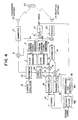
- molten metal 53 and slag 53 are in a convertor body 51.
- a hood 54 is provided at the upper portion of the convertor body 51.
- a smoke duct 55 is attached to the hood 54.
- a boiler piping 56 for recycle exhaust heat is attached to both the inner wall of the hood 54 and the inner wall of th smoke duct 55.
- Holes 57 and 58 for insertion of a mainlance 71 and a sublance 72 are provided in the hood 54.
- a beam 60 is provided near the convertor.
- a rotator 61 constituted by an electric motor is attached to the beam 60.
- the rotator 61 is linked with a hinge 62 to rotate it.
- a lift 63 constituted by an electric motor is attached to an end of the hinge 62.
- a microwave radar 73 is connected to transmission and reception antennas 23 and 24 through a waveguide 74 which is supported by the lift 63 so that the vertical position thereof is controlled.
- the vertical position of the waveguide 74 is controlled by the lift 63 and the position thereof in a two-dimensional plane is controlled by the rotator 61.
- the mechanism for supporting the sublance 72 is the same as that for supporting the waveguide. That is, a rotator 61a is attached to the beam 62 and linked with a hinge 62a to rotate it. A lift 63a is attached to an end of the hinge 62a, so that the sublance 72 is supported by the lift 63a to control the vertical position thereof.
- the sublance 72 is inserted into the furnace to perform molten metal temperature measurement and sampling. That is, as shown in Fig. 3, there is a risk of slopping caused by an abnormal reaction in the slag melting period of about 6 minutes after ignition. In the best decarbonization period after that, there is a risk of slopping because the slag level is relatively high.
- an anti-foaming agent such as coke breeze, limestone, etc. is put into the furnace. After about 11 minutes from ignition, the refining procedure goes to the low carbon period. In the low carbon period, there is no risk of slopping because the slag level is relatively low and stable. However, there is the necessity of sampling for molten metal temperature measurement and molten metal composition adjustment in the last stage of the refining procedure. Therefore, the sublance 72 is inserted into the furnace.
- Figs. 1 and 2 show the state where the antennas 23 and 24 are inserted into the convertor in the refining procedure to measure the level of the slag 53.
- the lift 63 is adjusted to the hole 58 of the hood 54 by rotating the rotator 61 under the condition that the antennas 23 and 24 are elevated up.
- the antennas 23 and 24 are inserted into the convertor through the hole 58 by dropping down the waveguide 74 by operating the lift 63.
- the dropping of the waveguide 74 is stopped.
- the sublance 72 is retreated by operating the lift 63a and the rotator 61a.
- the level of the slag 53 is measured by the microwave radar 73.
- the construction and function of the microwaver radar 73 will be described later.
- the antennas 23 and 24 are retreated and at the same time the sublance 72 is inserted into the furnace.
- the operation at this time is as follows.
- the antennas 23 and 24 are elevated up out of the hole 58 of the hood 54 by operating the lift 63 and then the antennas 23 and 24 are moved to a suitable position in a two dimensional plane by the rotator 61.
- the lift 63a is adjusted to the hole 58 of the hood 54 by operating the rotator 61a. Then, the sublance 72 is dropped by operating the lift 63a so as to be inserted into the convertor through the hole 58. The dropping of the sublance 72 is stopped when the distance between the sublance 72 and the surface of the slag 53 takes a suitable value.
- the invention can be applied to the case where the retreat of the antennas 23 and 24 and the insertion of the lance 72 are made so synchronously as to be free from collision to thereby smoothen the alternating operation more.
- the modified technique in the latter case can be applied to the retreat of the lance 72 and the insertion of the antennas 23 and 24.
- a microwave radar 73 according to a further embodiment of the invention depicted in Fig. 4.
- the reference numerals 1 and 2 designate clock generators respectively, and 3 and 4 designate pseudo random signal generators respectively.
- the reference numerals 5 through 9 designate multipliers, for example, constituted by double-balanced mixers respectively.
- the reference numerals 10 through 12 designate low-pass filters respectively, 13 and 14 designate distributors respectively, 15 and 16 designate squarers respectively, 17 designates an adder, 18 designates a time measurer, 19 designates a carrier oscillator, 20 designates a hybridcoupler, 21 designates a transmitter, 22 designates a receiver, 23 designates a transmission antenna, 24 designates a reception antenna and 25 designates a target (slag surface in the furnace).
- each of the pseudo random signal generators 3 and 4 may be constituted by an M-type signal generator.
- the M-type signal generator may be a 7-bit M-type signal generator.
- the M-type signal generator may be a 7-bit M-type signal generator constituted by a shift register 30 of a 7-stage structure and an exclusive OR circuit 31, as shown in Fig. 6, the shift register 30 being of a 7-stage structure composed, for example, of ECL (emitter-coupled logic) elements.
- the M-type signal is a periodically circulating signal having a combination of codes "1" (corresponding to a positive voltage +E).
- Each of the pseudo random signal generators 3 and 4 is constituted by one and the same circuit, so that the output signals of the pseudo random siganl generators 3 and 4 have the same pattern. However, the pseudo random signal generators 3 and 4 are slightly different in clock frequency supplied thereto, so that they are slightly different in one period thereof. Other than the M-type signal, a Gold-type signal or a JPL-type signal may be used as a pseudo random signal.
- Each of the clock generators 1 and 2 includes a quartz oscillator by which a clock signal sufficiently stable in frequency is generated. However, the clock generators 1 and 2 are slightly different in the frequency generated. In this embodiment, the frequencies f1 and f2 generated by the clock generators 1 and 2 are 100.004 MHz and 99.996 MHz, respectively, so that the difference f1-f2 between the frequencies is 8 KHz.
- the clock signals f1 and f2 respectively generated from the clock generators 1 and 2 are respectively supplied to the pseudo random signal generators 3 and 4.
- the pseudo random signal generators 3 and 4 generate M-type signals M1 and M2 slightly different in one period thereof but of the same pattern, on the basis of the difference in frequency between the driving clock signals.
- the respective frequencies of the two M-type signals M2 and M2 can be calculated as follows.
- (Frequency of M1) 127 x 1/100.004 MHz ⁇ 1269.9492 ns
- (Frequency of M2) 127 x 1/99.996 MHz ⁇ 1270.0508 ns
- the two M-type signals M1 and M2 have the substantially the same period of about 1270 ns (10 -9 sec) but have a time difference of about 0.1 ns. Therefore, if the two M-type signals M1 and M2 are circulatedly generated and then the patterns of the two M-type signals are matched with each other at a certain point of time ta, a time difference of 0.1 ns arises between the two signals whenever one period is passed, or in other words, a time difference of 10 ns arises between the two signals when 100 periods are passed.
- the time required for generating one signal-chip is 10 ns. Accordingly, the fact that a time difference of 10ns arises between the two M-type signals M1 and M2 represents the fact that the M-type signals are diverged by one signal-chip from each other.
- the output M1 of the pseudo random signal generator 3 is supplied to the multipliers 5 and 6.
- the output M2 of the pseudo random signal generator 4 is supplied to the multipliers 5 and 7.
- the carrier generator 19 generates a microwave having a frequency of about 17 GHz.
- the output signal of the carrier generator 19 is distributed, by the distributor 13, into the multiplier 6 and the hybrid coupler 20.
- the multiplier 6 is constituted by a double-balanced mixer. The multiplier 6 multiplies the carrier of about 17 GHz fed from the distributor 13 by the M-type signal M1 fed from the pseudo random signal generator 3 and feeds the transmitter 21 with a spectrum diffused signal formed by phase-modulating the carrier.
- the transmitter 21 power-amplifies the input spectrum-diffused signal, converts it into an electromagnetic wave through the transmission antenna and radiates it toward the target 25. Because the wavelength of the electromagnetic wave having a frequency of 17 GHz is 1.3cm in air and is sufficiently larger than the size (diameter) of dust in an iron-manufacturing furnace, there is little influence of dust or the like.
- each of the transmission antenna 23 and the reception antenna 24 is constituted by a horn antenna to narrow down the directivity sharply to thereby reduce electric power reflected on matters other than the target, as sufficiently as possible for example, each of the transmission antenna 23 and the reception antenna 24 has an antenna gain of about 20dB.
- the electromagnetic wave radiated from the transmission antenna 23 toward the target 25 (corresponding to the slag 53 of Fig. 1) is reflected on the target 25, converted into an electric signal through the reception antenna 24 and fed to the receiver 22.
- the point of time when the input signal is supplied to the receiver 22 is delayed from the point of time when the electromagnetic wave is radiated from the transmission antenna 23 by the propagation time of the electromagnetic wave which is taken for the electromagnetic propagates forward from the transmission antenna 23 to the target 25 and then propagates back from the target 25 to the reception antenna 24.
- the receiver 22 amplifies the input signal and feeds the amplified signal to the multiplier 7.
- the M-type signals M1 and M2 respectively fed from the pseudo random signal generators 3 and 4 to the multiplier 5 are multiplied by each other.
- the time series signal representing the multiplication value is supplied to the low-pass filter 10.
- the input signal the low-pass filter 10, that is, the time series signal representing the output value of the multiplier 5, has a waveform as shown in the diagram (a) of Fig. 5.
- an output voltage +E is continued.
- an output voltage +E and an output voltage -E are produced at random.
- the low-pass filters 10 through 12 have a kind of integral function based on the band limitation for frequency. Accordingly, when the phases of the two signals are matched with each other, the output signal from the low-pass filters 10 through 12 as a signal formed by integrating correlative operation values of the two signals is a pulse-like signal as shown in the diagram (b) of Fig. 5. When the phases of the two signals are not matched with each other, the output signal from the low-pass filters has a value of 0. Therefore, a periodic pulse-like signal is produced in the output of the low-pass filter 10. The pulse-like signal as a reference signal for time is supplied to the time measurer 18.
- the period TB of the reference signal calculated on the basis of the aforementioned equation (1) is 15.875 ms, because f1 and f2 are 100.004 MHz and 99.996 MHz, respectively.
- the reference signal and the period TB thereof are shown in the diagram (d) of Fig. 5.
- the reception signal from the receiver 22 and the M-type signal M2 from the pseudo random signal generator 4 are fed to the multiplier 7 and multiplied by each other.
- the modulated phase of the reception signal formed by phase-modulating the transmission carrier on the basis of the first M-type signal M1 is matched with the phase of the second M-type signal M2
- the multiplication result from the multiplier 7 as a matched-phase carrier signal is supplied to the distributor 14.
- the modulated phase of the reception signal is not matched with the phase of the M-type signal M2
- the multiplication result from the multiplier 7 as a random-phase carrier signal is supplied to the distributor 14.
- the distributor 14 distributes the input signal into the two multipliers 8 and 9, that is, the two output signals R1 and R from the distributor 14 are supplied to the multipliers 8 and 9, respectively.
- the hybrid coupler 20 supplied with a part of the transmission carrier from the distributor 13 supplies the multipliers 8 and 9 with an in-phase (zero-phase) component signal I having the same phase as the phase of the input signal and a quadrature (90o -phase) component signal Q having a phase perpendicular to the phase of the input signal, respectively.
- the multiplier 8 multiplies the signal I (that is, the signal having the same phase as that of the output from the carrier oscillator 19) fed from the hybrid coupler 20 and the aforementioned signal R1 fed from the distributor 14 by each other.
- the multiplies 9 multiplies the input signal Q (that is, signal having a phase shifted by 90 degrees from the output of the carrier oscillator 19) and the aforementioned signal R2 by each other. Accordingly, the multipliers 8 and 9 respectively extract a zero-phase component (I ⁇ R1) and a 90°-phase component (Q ⁇ R2) from the reception signal and send out the two components as detected signals.
- the signals I ⁇ R1 and Q ⁇ R2 as detected signals are supplied to the low-pass filtrs 11 and 12, respectively.
- the low-pass filters 11 and 12 have an integral function based on band limitation of frequency. By the integral function, the low-pass filters 11 and 12 integrate correlative operation values of the two signals. That is, when the phase of the aforementioned signal R1 fed from the multiplier 7 to the multiplier 8 through the distributor 14 is matched with the phase of the aforementioned signal I fed from the hybrid coupler 20 to the multiplier 8 and when the aforementioned signal R2 fed to the multiplier 9 is matched with the signal Q fed to the multiplier 9, the output signals from the multipliers 8 and 9 become pulse signals of predetermined polarity (the voltage +E or the voltage -E) so that large voltage arise in the outputs of the low-pass filters 11 and 12 integrating the signals, respectively.
- predetermined polarity the voltage +E or the voltage -E
- the output signals from the multipliers 8 and 9 become pulse signals of randomly changed polarity (that is, the voltage +E and the voltage -E) so that zero voltage arises in the outputs of the low-pass filters 11 and 12 integrating the signals, respectively.
- the zero-phase and 90°-phase components thus subjected to the integral processing through the low-pass filters 11 and 12 are supplied to the squarers 15 and 16, respectively.
- the squarers 15 and 16 repectively square the amplitudes of the input signals and feed the output signals as operation results to the adder 17.
- the adder 17 adds the two input signals to each other and supplies a pulse-like detection signal as shown in the diagram (c) of Fig. 5 to the time measurer 18.
- the aforementioned technique having the steps of detecting zero-phase and 90° -phase components of transmission carrier respectively from a signal formed by the correlation processing of the reception signal and the M-type signal M2, integrating the detection signals and then squaring the integrated signals respectively, and adding the pair of squared values to each other to obtain a target detection signal, is more or less complex in configuration but can obtain a high-sensitive target detection signal.
- a high S/N Measuring system to reduce the influence of noise for the purpose of signal emphasis can be provided.
- a detection technique using crystal may be employed according to the specification and cost because the technique is inferior in sensitivity but simple in configuration.
- the time measurer 18 is composed of a propagation-time measurer 18a and a distance scaler 18b.
- the propagation-time measurer 18a measures the time TD between the point of time ta when the reference signal fed from the low-pass filter 10 takes its maximum and the point of time when the detection signal fed from the adder 10 takes its maximum and the point of time when the detection signal fed from the adder 17 takes its maximum. Therefore, the propagation-time measurer 18a has a function for detecting the time points when the two input signals respectively take the maximum value.
- the time point when an input signal takes its maximum value can be detected by detecting the time point of turning-over of the input signal (from increase to decrease for time) while temporarily comparing the present sample value and the previous sample value successively obtained by sample-holding of the input voltage value on the basis of the clock signal.
- the time TD represents a time between the time point ta of generation of the maximum value of the reference signal as shown in the diagram (d) of Fig. 5 and the time point tb of generation of the maximum value of the detection signal as shown in the diagram (c) of Fig. 5.
- the time TD can be calculated by increasing the propagation time ⁇ required for the electromagnetic wave actually moving forth and back as to the distance between the transmission and reception antennas 23 and 24 and the target 25 by f1/(f1-f2) times.
- TD 12,500 ⁇
- the time TD as expressed by the equation (4) is obtained for each period TB of the reference signal.
- the measurement apparatus according to the invention is suitable to a level meter for measuring short distance such as in-furnace slag level, melt level, etc.
- the distance x (meter) from the transmission and reception antennas 23 and 24 to the target 25 is represented by the following equation (5) when it is calculated according to the equation (4).
- the operation expressed by the equation (5) is carried out by the distance scaler 18b to generate a distance signal and a slag level measurement signal is obtained on the basis of the distance signal.
- each antenna was made to be a small-sized one having a diameter of 100mm so that the antenna could be inserted/removed through the small hole 58 of 270mm diameter formed in the hood 54.
- the slag level in the convertor could be measured with precision of 100mm and response speed of 3 seconds.
- Each of the microwave radar pseudo random signal generators 3 and 4 in Fig. 4 may have a configuration as shown in Fig. 6 or may have a configuration as shown in Fig. 7.
- the pseudo random signal generator as shown in Fig. 7 is composed of a counter 32, a storage device 33, and a signal convertor 34.
- the counter 32 receives a clock signal as an input signal, counts the input clock pulses and feeds the count value of clock pulses to the storage device 33.
- the counter 32 carries out a counting operation from 0 to a count upper-limit value n .
- the upper-limit value is 127, so that the counter 32 repeats the counting operation from 0 to 127 in synchronism with the fed clock signal.
- a synchronizing pulse signal is sent out to the outside.
- the storage device 33 has a memory for storing data, constituted by an ROM, an RAM, etc.
- the storage device 33 receives the output count value from the counter 32, reads code date of the pseudo random signal stored in the memory while using the count as an address of the memory and feeds the data to the signal convertor 34.
- the storage device 33 has a capacity for 128 data of the data length of 2 bits designated by addresses of from 0 to 128.
- the first bit of the respective data in memory represents the code pattern of the pseudo random signal to be stored. Accordingly, the first bit is set to "1" or "0" corresponding to the code "1" or "0" of the pseudo random signal.
- the second bit of the respective data in memory represents a judgment as to whether the data in memory is a code data of the pseudo random signal or not.
- the second bit is set to "1".
- the second bit is set to "0".
- Fig. 8 shows an example of a table in the case where a Barker code data of code length 7 are stored in the memory of the storage device 33.
- 2-bit data represented by "11" and “10" corresponding to the Barker code data are stored in address 0 through 6 of the memory and, at the same time, 2-bit data represented by "00" are stored in the other addresses 7 through 127 of the memory. Because data corresponding to the addresses 0 through 127 are successively read out on the basis of the input signal fed from the counter 32, the data reading operation in the storage device 33 is repeated in a period of 128 clock pulses in synchronism with the clock signal fed to the counter 32.
- a table of Fig. 9 shows the relationship between the input data and the output signal in the signal convertor 34 in this embodiment.
- the signal convertor 34 receives data from the storage device 33, converts the data into a three-value signal and sends out it. That is, when the 2-bit data fed from the storage device 33 in "11" or “10” as representing a code data, the signal convertor 34 generates a positive (+) or negative (-) signal corresponding to the data. When the 2-bit data is "00" or "01", the signal convertor 34 generates a zero signal.
- Fig. 10 shows to the waveform of the output signal from the signal convertor 34, that is, the waveform of the output signal from the pseudo random signal generator, in the case where data are fed from the storage device 33 having such memory content as shown in Fig. 8.
- a positive (+), negative (-) zero(0) signal is sent out correspondingly to the data read from the storage device 33. Because the operation of reading data from the storage device 33 is repeated in a period determined by the number of memory addresses in the storage device 33 in synchronism with the clock signal, the output signal from the signal convertor 34 has a waveform formed by repeating 7-clock-pulses Barker' code output signals and 121-clock-pulses' zero signals.
- clock signals of 30.002 MHz and 29.998 MHz and a carrier signal frequency of 10 GHz are used.
- Each of the pseudo random generators 3 and 4 has a structure as shown in Fig. 7. Barker codes having a code length of 7 and a zero signal having a predetermined duration are repeatedly generated in synchronism with the clock signal.
- the multiplier (modulator) 6 performs modulation of a carrier fed from the carrier oscillator 19 through the distributor 13 on the basis of the pseudo random signal fed from the pseudo random signal generator 3.
- the signal output from the pseudo random signal generator 3 is a three-value signal +, - or 0.
- phase-modulation is carried out correspondingly to the signal.
- the carrier output is stopped.
- the signal transmitted from the microwave radar to the target through the transmission antenna 23 becomes an intermittent signal.
- the receiver 22 used in the microwave radar receives, through the reception antenna 24, the signal reflected on the target, and performs the amplification or attenuation on the detection signal. That is, the receiver 22 is supplied with a synchronizing pulse signal from the pseudo random signal generator 3 as shown by a broken line in Fig. 4, so that the receiver 22 amplifies/attenuates the reflection signal while changing the factor of amplification or attenuation in synchronism with the synchronizing pulse signal and sends out the detection signal thus amplified/attenuated.
- the diagrams (a) and (b) of Fig. 11 respectively show the waveforms of the pseudo random signal and the synchronizing pulse signal as output signals from the pseudo random signal generator 3.
- the diagram (c) of Fig. 11 shows the time change of the signal amplification factor in the receiver 22.
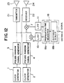
- the microwave radar according to another embodiment is shown in Fig. 12.
- the pseudo random signal generator shown in Fig. 6 or the pseudo random signal generator shown in Fig.7 is used and the pseudo random signal is directly used as a transmission signal.
- each of the pseudo random signal generators 3 and 4 has a structure as shown in Fig. 7 and performs generation of Barker codes having a code length of 7.
- the pseudo random signal from the pseudo random signal generator 3 is fed to the transmitter 21.
- the pseudo random signal fed to the transmitter 21 is power-amplified and then converted into an electro magnetic wave through the transmission antenna 23.
- the electromagnetic wave is radiated toward the target. Therefore, the microwave radar of Fig. 12 has a structure in which the carrier oscillator 19, the distributor 13 and the multiplier 6 in Fig. 4 are omitted.
- the electromagnetic wave from the transmission antenna 23 is reflected on the target and converted into an electric signal through the reception antenna 24. Then, the electric signal is fed to the receiver 22. Thereafter, the reception signal from the receiver 22 and the pseudo random signal from the pseudo random signal generator 4 are multiplied (mixed) by each other by the multiplier (mixer) 7. The multiplication result is fed to the low-pass filter 11. Accordingly, the distributor 14, the multipliers 8 and 9, the low-pass filter 12, the squarers 15 and 16, the adder 17 and the hybrid coupler 20 depicted in Fig. 4 are omitted in the configuration of this embodiment.
- the output from the low-pass filter 10 and the output from the low-pass filter 11 are fed to the propagation-time measurer 18a and then processed in the same manner as in the case of Fig. 4 to send out the slag level measurement signal from the distance scaler 18b.
- the detection signal based on the necessary reflected wave can be picked up through a time gating circuit by utilizing the advantage that the time for measurement of the distance to the target by the microwave radar is enlarged. Or in other words, the other detection signal based on the unnecessary reflected wave can be removed, so that the level position or the distance can be measured stably.
- the aforementioned embodiments have shown the case where a microwave of about 10 GHz is used as a carrier, it is a matter of course that the invention can be applied not only to the case where an electro magnetic wave of an extremely high frequency (EHF), or the like is used as a carrier but to the case where an electromagnetic wave such as light, an acoustic wave, an ultrasonic wave, or the like, is used as a carrier.
- EHF extremely high frequency
- the velocity of the target can be measured by additionally providing a timer into the aforementioned microwave radar to calculate the change of the measured distance to the target in unit time.
- microwave radar in this embodiment can be used for an in-furnace level meter which will be described later, but it can be used for measurement of the position of a target buried in the ground or in the water or for probing in the ground or the like.
- the microwave radar can be sufficiently used for measurement of the relatively large distance to a general target such as a flying matter, a ship, a car, etc., or for measurement of the position thereof if clock frequencies for generating two pseudo random signals are set suitably.
- the distance between the antenna and the in-furnace slag level is calculated on the basis of the time distance between the pulse peak of the detection signal and the pulse peak of the time reference signal, by which a good result can be attained. Further, the accuracy in measurement can be improved more by inputting the reflected signal into the microwave radar 52 after adjusting the strength of the reflected signal substantially to a predetermined level.
- Fig. 13 shows an embodiment in which the microwave radar is constructed so that the strength of the reflected signal can be adjusted.
- a signal strength changer 26 an average operation means 27 and a CRT displaying 28 are added to the apparatus of Fig. 4.
- this embodiment shows the case where the signal strength changer 26 is provided between the reception end of the microwave radar 52 and the reception antenna 24 inserted in the furnace, the invention can be applied to the case where it maybe provided between the transmission end of the microwave radar 52 and the transmission antenna 23.
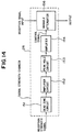
- Fig. 14 shows an embodiment of the signal strength changer 26.
- a control signal is calculated on the basis of the peak of the reception strength signal fed from the microwave radar 52, so that the quantity of attenuation of the reception signal is adjusted on the basis of the control signal.
- a variable attenuator 156 included in the signal strength changer 26 performs attenuation proportionally to the signal strength of the input control signal. When there is no input control signal, the signal is passed as it is.
- the reception strength signal from the adder 17 of the microwave radar 52 is inputted into a dead zone circuit 151.
- no control signal is generated so that there is no signal attenuating operation in the variable attenuation 156.
- the signal is amplified by the amplifier 152 and then inputted into the peak hold circuit 153.
- the peak hold circuit has a time constant of the same degree as the period of the input pulse signal and holds the peak of the input pulse as an output thereof.
- a control signal for the variable attenuator 116 is attained by amplifying the held signal by the amplifier 154 and adding an offset thereto, so that the quantity of attenuation in the variable attenuator 156 is determined on the basis of the control signal.
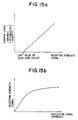
- Fig. 15a is a characteristic graph of the signal strength changer 26.
- the output change of the control signal against the input reception strength signal that is, the change of the quantity of attenuation in the variable attenuator 156.
- the control signal becomes a signal proportional to the reception strength signal.
- the limit value is established to be 0.7 V. Accordingly, when the maximum of time reception strength signal is not smaller than 0.7 V, a control signal is generated.
- Fig. 15b is a characteristic graph of the signal level in the whole measuring apparatus and showing the relationship between the reflected signal strength received by the reception antenna 24 and the reception strength signal.
- the value of the reception strength signal is also small. Accordingly, signal attenuation in the signal strength charger 26 is not made, so that the reflected signal strength is proportional to the reception strength signal.
- signal attenuation in the signal strength changer 26 is started. Accordingly, the change of the reception strength signal can be reduced to a small value when the reflected signal strength changes by a value of the order of tens of dB.
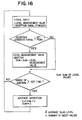
- Fig. 16 shows a flow chart of the average operation processing.
- the average operation means 27 receives both the level measurement value from the distance scaler 18b of the microwave radar 52 and the reception strength signal from the adder 17.
- the peak of the reception strength signal is larger than a predetermined not sets point
- the input level measurement value is added to the sum of the level values.
- the input level measurement value is not added.
- the average slag level is calculated by dividing the sum of the level values by the number of times for addition.
- the sum of the level values is set to zero and then preparation for the next average operation is made.
- the situation of the procedure returns to first and the next signal inputting operation is made.
- the situation of the procedure returns directly to the next signal inputting operation.
- the series of average operation processings are made by a personal computer, and a result of the operation of the average slag level is sent to the CRT display unit 28.
Landscapes
- Physics & Mathematics (AREA)
- Engineering & Computer Science (AREA)
- Radar, Positioning & Navigation (AREA)
- Remote Sensing (AREA)
- Electromagnetism (AREA)
- General Physics & Mathematics (AREA)
- Computer Networks & Wireless Communication (AREA)
- Chemical & Material Sciences (AREA)
- Fluid Mechanics (AREA)
- Thermal Sciences (AREA)
- Manufacturing & Machinery (AREA)
- Materials Engineering (AREA)
- Metallurgy (AREA)
- Organic Chemistry (AREA)
- Radar Systems Or Details Thereof (AREA)
- Measurement Of Levels Of Liquids Or Fluent Solid Materials (AREA)
Claims (11)
- Vorrichtung zum Messen des Schlackenniveaus in einem Ofen für einen Konverter (51) mit einer Haube (54), die mit einer Öffnung (58) zum Einsetzen einer Hilfslanze (72) und einem Baum (60) versehen ist, wobei die Schlakkenmeßvorrichtung eine Antenne (23,24) und ein Mikrowellen-Radargerät (73) aufweist, das mit der Antenne (23, 24) verbunden ist;
dadurch gekennzeichnet, daß die Vorrichtung ferner eine Einrichtung zum Drehen der Antenne (23,24) um den Baum (60) und eine Einrichtung zum Verschieben der Antenne in vertikaler Richtung in Bezug auf diesen aufweist, so daß die Antenne in den Konverter (51) durch die Öffnung (58) für die Hilfslanze (72) eingesetzt werden kann. - Vorrichtung zur Messung des Schlackenniveaus in einem Ofen nach Anspruch 1, welche aufweist:eine erste Dreheinrichtung (61), die am Baum (60) angebracht ist;ein erstes Stützorgan (62), das mit der ersten Dreheinrichtung (61) so verbunden ist, daß es um den Baum (60) durch die erste Dreheinrichtung (61) gedreht werden kann;eine erste Hubeinrichtung (63), die mit der Oberseite des ersten Stützorgans (62) verbunden ist, zum Steuern der Auf- und Abwärtsbewegung eines Wellenleiters (74), der mit der Antenne (23,24) verbunden ist;eine zweite Dreheinrichtung (61a), die am Baum (60) angebracht ist;ein zweites Stützorgan (62a), das mit der zweiten Dreheinrichtung (61a) derart verbunden ist, daß es um den Baum (60) durch die zweite Dreheinrichtung (61a) gedreht werden kann, sowieeine zweite Hubeinrichtung (63a), welche mit der Oberseite des zweiten Stützorgans (62a) zur Steuerung der Aufwärts- und Abwärtsbewegung einer Hilfslanze (72) verbunden ist.
- Vorrichtung zum Messen des Schlackenniveaus in einem Ofen nach Anspruch 1, bei welcher das Mikrowellen-Radargerät (73) eine Einrichtung zum Aussenden einer Mikrowelle, die mit einem Pseudozufallssignal moduliert ist, und zum Empfangen einer Reflexionswelle der Mikrowelle von der Oberfläche der Schlacke (53), eine Einrichtung zum Messen der Zeit der hin- und hergehenden Fortpflanzung der Mikrowelle zwischen dem Mikrowellen-Radargerät (73) und der Oberfläche der Schlacke (53) sowie eine Einrichtung zum Umwandeln der gemessenen Zeit in einen Abstand, aufweist.
- Vorrichtung zum Messen des Schlackenniveaus in einem Ofen nach Anspruch 3, bei welcher das Mikrowellen-Radargerät (73) umfaßt:einen ersten Pseudozufallssignal-Generator (3) zum Ausgeben eines ersten Pseudozufallssignals;einen zweiten Pseudozufallssignal-Generator (4) zum Ausgeben eines zweiten Pseudozufallssignals mit einem gleichen Muster wie das erste Pseudozufallssignal sowie mit einer etwas von der Frequenz des ersten Pseudozufallssignals unterschiedlichen Frequenz;einen ersten Multiplier (5) zum Vervielfachen des ersten und zweiten Pseudozufallssignals jeweils durch das andere;einen Trägerfrequenz-Generator (19);eine Sendeeinrichtung (21) zum Senden eines Sendesignals auf der Grundlage des ersten Pseudozufallssignals zu der Schlackenoberfläche;eine Empfangseinrichtung (22) zum Empfangen eines Reflexionssignals von der Schlackenoberfläche, um dadurch ein Empfangssignal zu erhalten;einen zweiten Multiplier (7) zum Vervielfachen des Empfangssignals durch das zweite Pseudozufallssignal, um dadurch eine Trägerfrequenz auszugeben;einen Detektor zum Erfassen der vom zweiten Multiplier ausgegebenen Trägerfrequenz, um dadurch ein Erfassungssignal zu erhalten; undeine Zeitdifferenz-Meßeinrichtung (18) zum Messen einer Zeitdifferenz zwischen dem Zeitsteuermuster des vom Detektor ausgegebenen Erfassungssignals und dem Zeitsteuermuster eines Vielfachwert-Ausgangssignals aus dem ersten Multiplier (5).
- Vorrichtung zum Messen des Schlackenniveaus in einem Ofen nach Anspruch 4, bei welcher das Mikrowellen-Radargerät (73) einen Trägerfrequenz-Generator (19) zum Erzeugen einer Trägerfrequenz enthält, die als mit dem ersten Pseudozufallssignal moduliertes Sendesignal ausgegeben wird.
- Vorrichtung zum Messen des Schlackenniveaus in einem Ofen nach Anspruch 5, in welcher der Detektor enthält:einen ersten Verteiler (13) zum Herausnehmen eines Teils des Ausgangssignals des Trägerfrequenz-Generators;einen Hybridkoppler (20), auf den ein Ausgangssignal des ersten Verteilers (13) gegeben wird, zum Umwandeln des Ausgangssignals in eine In-Phase-Komponente, nämlich ein I-Signal, und eine Quadraturkomponente bzw. 90° phasenverschobene Komponente , nämlich ein Q-Signal, wobei das I- und Q-Signal jeweils einander senkrecht schneidende Phasen besitzen;einen zweiten Verteiler (14) zum Verteilen des Ausgangssignals des zweiten Multipliers (7) in zwei Signale, nämlich ein R1-Signal und ein R2-Signal;einen dritten Multiplier (8) zum Vervielfachen des vom Hybridkoppler (20) ausgegebenen I-Signals durch das Rl-Signal, das vom zweiten Verteiler (14) ausgegeben wird; undeinen vierten Multiplier (9) zum Vervielfachen des vom Hybridkoppler (20) ausgegebenen Q-Signals durch das R2-Signal, das vom zweiten Verteiler (14) ausgegeben wird.
- Vorrichtung zum Messen des Schlackenniveaus in einem Ofen nach Anspruch 5, bei welcher die Zeitdifferenz-Meßeinrichtung umfaßt:ein erstes Tiefpaßfilter (10), auf das das Ausgangssignal des ersten Multipliers (5) gegeben wird, um dadurch eine Bandbegrenzung durchzuführen;ein zweites (11) und drittes (12) Tiefpaßfilter, auf die die Ausgangssignale des dritten (8) bzw. vierten (9) Multipliers gegeben werden, um dadurch unabhängig voneinander Bandbegrenzungen durchzuführen;einen ersten (15) und zweiten (16) Rechteckwellenumformer (squarer), auf welchen die Ausgangssignale des zweiten (11) bzw. dritten (12) Tiefpaßfilters gegeben werden, um dadurch Rechteckwellenumformungen unabhängig voneinander durchzuführen;eine Addiereinrichtung (17) zum Addieren der jeweiligen Ausgangssignale des ersten (15) und zweiten (16) Rechteckwellenumformers miteinander; undeine Zeitmeßeinrichtung (18a) zum Messen der Zeit zwischen einem Zeitpunkt, in welchem das Ausgangssignal des ersten Tiefpaßfilters (10) seinen Maximalwert annimmt, und einem Zeitpunkt, in welchem das Ausgangssignal der Addiereinrichtung (17) seinen Maximalwert annimmt.
- Vorrichtung zum Messen des Schlackenniveaus in einem Ofen nach Anspruch 5, bei welcher sowohl der erste als auch zweite Pseudozufallssignal-Generator umfaßt:einen Zähler (32) zum Zählen von Taktsignalimpulsen, um dadurch einen Zählwert auszugeben;eine Speichereinrichtung (33), aus der gespeicherte Daten ausgelesen werden, während der von dem Zähler (32) gelieferte Zählwert als Adresse verwendet wird;einen Signalkonverter (34) zum Umwandeln der ausgelesenen Speicherdaten in ein Drei-Werte-Signal als Ausgangssignal desselben;wobei die Empfangseinrichtung (22) in der Lage ist, die Signalempfangs-Empfindlichkeit mit dem Verstreichen der Zeit synchron zur Periode des Pseudozufallssignals zu ändern.
- Vorrichtung zum Messen des Schlackenniveaus in einem Ofen nach Anspruch 5, mit einer Signalstärke-Änderungseinrichtung (26), welche zwischen die Sendeeinrichtung (21) und die Sendeantenne (23) oder zwischen die Empfangsantenne (24) und die Empfangseinrichtung (22) geschaltet ist, zum Ausgeben eines Eingangsmikrowellen-Stärkesignals zum Ändern des Eingangsmikrowellen-Stärkesignals entsprechend einem vom Detektor ausgegebenen Empfangsstärkesignals.
- Vorrichtung zum Messen des Schlackenniveaus in einem Ofen nach Anspruch 9, mit einer Durchschnittsbetriebseinrichtung (27) zur Durchschnittsbildung des Niveaumeßwertes des Niveaumeßwertsignals.
- Vorrichtung zum Messen des Schlackenniveaus in einem Ofen nach Anspruch 10, bei welcher die Durchschnittsbetriebseinrichtung (27) den Niveaumeßwert vernachlässigt, wenn der Wert des Empfangsstärkesignals niedriger ist als ein gegebener Wert.
Applications Claiming Priority (6)
| Application Number | Priority Date | Filing Date | Title |
|---|---|---|---|
| JP2081312A JPH0760181B2 (ja) | 1990-03-30 | 1990-03-30 | 距離計測装置 |
| JP81313/90 | 1990-03-30 | ||
| JP81312/90 | 1990-03-30 | ||
| JP81314/90 | 1990-03-30 | ||
| JP2081313A JPH0826386B2 (ja) | 1990-03-30 | 1990-03-30 | 炉内のスラグレベル計測装置 |
| JP2081314A JPH0826387B2 (ja) | 1990-03-30 | 1990-03-30 | 転炉内のスラグレベル計測方法及び装置 |
Publications (3)
| Publication Number | Publication Date |
|---|---|
| EP0451987A2 EP0451987A2 (de) | 1991-10-16 |
| EP0451987A3 EP0451987A3 (en) | 1992-12-02 |
| EP0451987B1 true EP0451987B1 (de) | 1997-09-10 |
Family
ID=27303555
Family Applications (1)
| Application Number | Title | Priority Date | Filing Date |
|---|---|---|---|
| EP91302653A Expired - Lifetime EP0451987B1 (de) | 1990-03-30 | 1991-03-26 | Verfahren und Gerät zur Schlackenniveaumessung in einem Ofen |
Country Status (8)
| Country | Link |
|---|---|
| US (1) | US5182565A (de) |
| EP (1) | EP0451987B1 (de) |
| KR (1) | KR910017175A (de) |
| CN (1) | CN1055391A (de) |
| AU (1) | AU7375191A (de) |
| BR (1) | BR9101251A (de) |
| CA (1) | CA2038823A1 (de) |
| DE (1) | DE69127575T2 (de) |
Families Citing this family (24)
| Publication number | Priority date | Publication date | Assignee | Title |
|---|---|---|---|---|
| US5233352A (en) * | 1992-05-08 | 1993-08-03 | Cournane Thomas C | Level measurement using autocorrelation |
| US5406842A (en) * | 1993-10-07 | 1995-04-18 | Motorola, Inc. | Method and apparatus for material level measurement using stepped frequency microwave signals |
| US5440310A (en) * | 1994-02-14 | 1995-08-08 | Motorola, Inc. | Bandwidth synthesized radar level measurement method and apparatus |
| US5614831A (en) * | 1995-02-13 | 1997-03-25 | Saab Marine Electronics Ab | Method and apparatus for level gauging using radar in floating roof tanks |
| DE19810601A1 (de) * | 1998-03-12 | 1999-09-16 | Daimler Benz Aerospace Ag | Anordnung zur Füllstandsmessung |
| DE59814044D1 (de) * | 1998-05-05 | 2007-08-09 | Endress & Hauser Gmbh & Co Kg | Mit Mikrowellen arbeitendes Füllstandsmessgerät |
| US6130637A (en) * | 1998-08-18 | 2000-10-10 | Usx Corporation | Measuring the thickness of hot slag in steelmaking |
| US6166681A (en) | 1998-08-18 | 2000-12-26 | Usx Corporation | Measuring the thickness of materials |
| US20050133192A1 (en) * | 2003-12-23 | 2005-06-23 | Meszaros Gregory A. | Tundish control |
| DE102005057094B4 (de) * | 2005-11-30 | 2013-02-14 | Vega Grieshaber Kg | Füllstandradar mit variabler Sendeleistung |
| DE102006003950A1 (de) | 2006-01-26 | 2007-08-30 | Heraeus Electro-Nite International N.V. | Vorrichtung zum Bestimmen einer Grenzfläche einer Schlackeschicht |
| US8482295B2 (en) | 2009-02-23 | 2013-07-09 | Hatch Ltd. | Electromagnetic bath level measurement for pyrometallurgical furnaces |
| MX2012009815A (es) * | 2010-02-26 | 2012-09-12 | Tenova Goodfellow Inc | Sistema para prediccion de vaciado de horno y optimizacion de lanza. |
| AT509736B1 (de) * | 2010-05-14 | 2012-03-15 | Inteco Special Melting Technologies Gmbh | Verfahren und vorrichtung zur kontinuierlichen erfassung des schlackenniveaus in esu-anlagen mit kurzen gleitkokillen |
| PL2393341T3 (pl) * | 2010-06-01 | 2013-02-28 | Dango & Dienenthal Maschbau | Sposób i urządzenie do pomiaru długości elektrody |
| KR20130093521A (ko) * | 2010-07-12 | 2013-08-22 | 가부시기가이샤니레꼬 | 거리 측정 장치 및 거리 측정 방법 |
| TWI415946B (zh) * | 2010-08-24 | 2013-11-21 | China Steel Corp | 高爐排渣流量估測系統與估測方法 |
| DE102011082367A1 (de) * | 2011-09-08 | 2013-03-14 | Endress + Hauser Gmbh + Co. Kg | Verfahren zur Füllstandsmessung nach dem Laufzeitprinzip |
| WO2013164214A1 (de) * | 2012-05-04 | 2013-11-07 | Siemens Vai Metals Technologies Gmbh | Kontaktlose positionsmessung einer beweglichen lanze bei der konverterstahlerzeugung |
| DE102012211714A1 (de) * | 2012-07-05 | 2014-05-22 | Siemens Vai Metals Technologies Gmbh | Verfahren und Vorrichtung zur Detektion des Schlackepegels in einem metallurgischen Gefäß |
| DE102015120736B4 (de) | 2015-11-30 | 2022-07-14 | Endress+Hauser SE+Co. KG | Verfahren und Füllstandsmessgerät zur Bestimmung des Füllstands eines in einem Behälter befindlichen Füllgutes |
| JP6822388B2 (ja) * | 2017-12-12 | 2021-01-27 | 日本製鉄株式会社 | レベル計測装置 |
| CN113195746B (zh) * | 2018-12-17 | 2023-10-20 | 日本制铁株式会社 | 炉内残留熔渣量的估计方法和估计装置 |
| CN111256779B (zh) * | 2020-01-19 | 2022-02-11 | 太原理工大学 | 基于热辐射理论的熔融炉熔融物界面位置检测系统及方法 |
Family Cites Families (12)
| Publication number | Priority date | Publication date | Assignee | Title |
|---|---|---|---|---|
| US3701518A (en) * | 1969-10-03 | 1972-10-31 | Berry Metal Co | Oxygen lance control arrangement for basic oxygen furnace |
| US3727897A (en) * | 1971-02-17 | 1973-04-17 | Avco Corp | Lance with distance measuring sub-system |
| FR2286390A1 (fr) * | 1974-09-27 | 1976-04-23 | Snecma | Procede et dispositif de correlation utilisables dans un radar a effet doppler |
| LU74321A1 (de) * | 1976-02-09 | 1976-08-13 | ||
| JPS53118161A (en) * | 1977-03-25 | 1978-10-16 | Sumitomo Metal Ind | Measuring method of slug forming by micro wave level meter |
| US4442513A (en) * | 1982-02-05 | 1984-04-10 | The Bendix Corporation | Sonar transceiver system and method |
| CA1260557A (en) * | 1984-03-30 | 1989-09-26 | Merlin D. Bjorke | Pulse synchronizing apparatus |
| US4933916A (en) * | 1985-11-01 | 1990-06-12 | Canadian Patents And Development Limited | Phase measurements using pseudo-random code |
| NL8602195A (nl) * | 1986-08-29 | 1988-03-16 | Hoogovens Groep Bv | Oxystaalfabriek. |
| US4821215A (en) * | 1986-10-03 | 1989-04-11 | Canadian Corporate Management Company Limited | Monitoring equipment for adverse environments |
| NL8700371A (nl) * | 1987-02-16 | 1988-09-16 | Hoogovens Groep Bv | Sub-lansinrichting voor het doen van metingen en/of het nemen van monsters in een metallurgische oven. |
| US4758839A (en) * | 1987-07-22 | 1988-07-19 | Mcdonnell Douglas Corporation | Terrain profile radar system |
-
1991
- 1991-03-21 CA CA002038823A patent/CA2038823A1/en not_active Abandoned
- 1991-03-22 AU AU73751/91A patent/AU7375191A/en not_active Abandoned
- 1991-03-26 DE DE69127575T patent/DE69127575T2/de not_active Expired - Fee Related
- 1991-03-26 EP EP91302653A patent/EP0451987B1/de not_active Expired - Lifetime
- 1991-03-27 US US07/675,759 patent/US5182565A/en not_active Expired - Fee Related
- 1991-03-28 CN CN91102033A patent/CN1055391A/zh active Pending
- 1991-03-28 BR BR919101251A patent/BR9101251A/pt not_active Application Discontinuation
- 1991-03-28 KR KR1019910004870A patent/KR910017175A/ko not_active Ceased
Also Published As
| Publication number | Publication date |
|---|---|
| AU7375191A (en) | 1991-10-03 |
| KR910017175A (ko) | 1991-11-05 |
| BR9101251A (pt) | 1991-11-05 |
| US5182565A (en) | 1993-01-26 |
| DE69127575T2 (de) | 1998-04-16 |
| DE69127575D1 (de) | 1997-10-16 |
| CN1055391A (zh) | 1991-10-16 |
| CA2038823A1 (en) | 1991-10-01 |
| EP0451987A3 (en) | 1992-12-02 |
| EP0451987A2 (de) | 1991-10-16 |
Similar Documents
| Publication | Publication Date | Title |
|---|---|---|
| EP0451987B1 (de) | Verfahren und Gerät zur Schlackenniveaumessung in einem Ofen | |
| US5115242A (en) | In-furnace slag level measuring apparatus | |
| EP0444834A2 (de) | Füllstandmessgerät in einem Ofen und Antenne dafür | |
| KR930001549B1 (ko) | 거리측정 방법 및 그 장치 | |
| USRE35607E (en) | Distance measuring method and apparatus therefor | |
| KR940009241B1 (ko) | 거리측정 방법 및 그 장치 | |
| EP2659239B1 (de) | Radarpegelmessung mit frequenzmodulierter gepulster welle | |
| GB1594395A (en) | Method and apparatus for measuring slag foaming using microwave level meter | |
| EP2187235B1 (de) | Entfernungsmessgerät und entfernungsmessmethode | |
| JPH1152049A (ja) | 炉内の湯面レベル計測装置 | |
| JP2570886B2 (ja) | 炉内レベル計 | |
| JPH03281717A (ja) | 転炉内のスラグレベル計測方法及び装置 | |
| EP2725330A1 (de) | Metallschmelze-füllstandsmessvorrichtung und metallschmelze-füllstandsmessverfahren | |
| JPH0826386B2 (ja) | 炉内のスラグレベル計測装置 | |
| JPH03281712A (ja) | 高炉鋳床脱珪処理方法 | |
| JP2961798B2 (ja) | 鋼の連続鋳造方法及び装置 | |
| JPS63229385A (ja) | 高炉口部におけるガス流速測定装置 | |
| JPH03282283A (ja) | 距離計測装置 | |
| JPH05307078A (ja) | 擬似ランダム信号発生器を用いた測定装置 | |
| JPS6136563B2 (de) | ||
| RU2805901C1 (ru) | Способ и устройство радиолокационного определения параметров движения отцепов на сортировочной горке | |
| JPS63120271A (ja) | レ−ダ型地中探査装置 | |
| JP2018053347A (ja) | スラグ高さ測定装置、スラグ高さ測定方法および溶銑の予備処理方法 | |
| JP2962983B2 (ja) | Cwドプラ計測レーダ装置 | |
| JPH04167962A (ja) | 混銑車注入溶銑レベル連続計測方法 |
Legal Events
| Date | Code | Title | Description |
|---|---|---|---|
| PUAI | Public reference made under article 153(3) epc to a published international application that has entered the european phase |
Free format text: ORIGINAL CODE: 0009012 |
|
| AK | Designated contracting states |
Kind code of ref document: A2 Designated state(s): AT BE DE ES FR GB IT NL SE |
|
| PUAL | Search report despatched |
Free format text: ORIGINAL CODE: 0009013 |
|
| RBV | Designated contracting states (corrected) |
Designated state(s): DE FR GB |
|
| AK | Designated contracting states |
Kind code of ref document: A3 Designated state(s): AT BE DE ES FR GB IT NL SE |
|
| 17P | Request for examination filed |
Effective date: 19930223 |
|
| 17Q | First examination report despatched |
Effective date: 19950103 |
|
| GRAG | Despatch of communication of intention to grant |
Free format text: ORIGINAL CODE: EPIDOS AGRA |
|
| GRAH | Despatch of communication of intention to grant a patent |
Free format text: ORIGINAL CODE: EPIDOS IGRA |
|
| GRAH | Despatch of communication of intention to grant a patent |
Free format text: ORIGINAL CODE: EPIDOS IGRA |
|
| GRAA | (expected) grant |
Free format text: ORIGINAL CODE: 0009210 |
|
| AK | Designated contracting states |
Kind code of ref document: B1 Designated state(s): DE FR GB |
|
| REF | Corresponds to: |
Ref document number: 69127575 Country of ref document: DE Date of ref document: 19971016 |
|
| ET | Fr: translation filed | ||
| PLBE | No opposition filed within time limit |
Free format text: ORIGINAL CODE: 0009261 |
|
| STAA | Information on the status of an ep patent application or granted ep patent |
Free format text: STATUS: NO OPPOSITION FILED WITHIN TIME LIMIT |
|
| 26N | No opposition filed | ||
| PGFP | Annual fee paid to national office [announced via postgrant information from national office to epo] |
Ref country code: FR Payment date: 19990309 Year of fee payment: 9 |
|
| PGFP | Annual fee paid to national office [announced via postgrant information from national office to epo] |
Ref country code: GB Payment date: 19990325 Year of fee payment: 9 |
|
| PGFP | Annual fee paid to national office [announced via postgrant information from national office to epo] |
Ref country code: DE Payment date: 19990406 Year of fee payment: 9 |
|
| PG25 | Lapsed in a contracting state [announced via postgrant information from national office to epo] |
Ref country code: GB Free format text: LAPSE BECAUSE OF NON-PAYMENT OF DUE FEES Effective date: 20000326 |
|
| GBPC | Gb: european patent ceased through non-payment of renewal fee |
Effective date: 20000326 |
|
| PG25 | Lapsed in a contracting state [announced via postgrant information from national office to epo] |
Ref country code: FR Free format text: LAPSE BECAUSE OF NON-PAYMENT OF DUE FEES Effective date: 20001130 |
|
| REG | Reference to a national code |
Ref country code: FR Ref legal event code: ST |
|
| PG25 | Lapsed in a contracting state [announced via postgrant information from national office to epo] |
Ref country code: DE Free format text: LAPSE BECAUSE OF NON-PAYMENT OF DUE FEES Effective date: 20010103 |