EP0449490B1 - Optisches Abtastgerät - Google Patents
Optisches Abtastgerät Download PDFInfo
- Publication number
- EP0449490B1 EP0449490B1 EP91302400A EP91302400A EP0449490B1 EP 0449490 B1 EP0449490 B1 EP 0449490B1 EP 91302400 A EP91302400 A EP 91302400A EP 91302400 A EP91302400 A EP 91302400A EP 0449490 B1 EP0449490 B1 EP 0449490B1
- Authority
- EP
- European Patent Office
- Prior art keywords
- light beam
- path
- scanning
- light
- light beams
- Prior art date
- Legal status (The legal status is an assumption and is not a legal conclusion. Google has not performed a legal analysis and makes no representation as to the accuracy of the status listed.)
- Expired - Lifetime
Links
Images

Classifications
-
- G—PHYSICS
- G06—COMPUTING OR CALCULATING; COUNTING
- G06K—GRAPHICAL DATA READING; PRESENTATION OF DATA; RECORD CARRIERS; HANDLING RECORD CARRIERS
- G06K7/00—Methods or arrangements for sensing record carriers, e.g. for reading patterns
- G06K7/10—Methods or arrangements for sensing record carriers, e.g. for reading patterns by electromagnetic radiation, e.g. optical sensing; by corpuscular radiation
- G06K7/10544—Methods or arrangements for sensing record carriers, e.g. for reading patterns by electromagnetic radiation, e.g. optical sensing; by corpuscular radiation by scanning of the records by radiation in the optical part of the electromagnetic spectrum
- G06K7/10821—Methods or arrangements for sensing record carriers, e.g. for reading patterns by electromagnetic radiation, e.g. optical sensing; by corpuscular radiation by scanning of the records by radiation in the optical part of the electromagnetic spectrum further details of bar or optical code scanning devices
- G06K7/10861—Methods or arrangements for sensing record carriers, e.g. for reading patterns by electromagnetic radiation, e.g. optical sensing; by corpuscular radiation by scanning of the records by radiation in the optical part of the electromagnetic spectrum further details of bar or optical code scanning devices sensing of data fields affixed to objects or articles, e.g. coded labels
- G06K7/10871—Methods or arrangements for sensing record carriers, e.g. for reading patterns by electromagnetic radiation, e.g. optical sensing; by corpuscular radiation by scanning of the records by radiation in the optical part of the electromagnetic spectrum further details of bar or optical code scanning devices sensing of data fields affixed to objects or articles, e.g. coded labels randomly oriented data-fields, code-marks therefore, e.g. concentric circles-code
Definitions
- This invention relates to optical scanning apparatus for scanning coded symbols provided on objects.
- the invention has a particular application to an optical bar code scanning system which can be mounted in or on a check-out counter for scanning bar code labels on an article which is moved past a scanning aperture located in the bar code scanner.
- data pertaining to the purchase of a merchandise item is obtained by reading data encoded indicia such as a bar code printed on the merchandise item.
- data encoded indicia such as a bar code printed on the merchandise item.
- UPC uniform product code
- Various reading systems have been constructed to read this bar code, including optical reader systems normally located within the checkout counter in which the bar code is read by projecting a plurality of scanning light beams at a window constituting the scanning area of the counter over which a purchased merchandise item supporting a bar code label is moved. It is found with such reading systems that attempts to scan the coded symbols or objects passed over the scanning window often result in invalid read scans.
- the document EP-A-0 152 733 discloses an optical scanner which utilizes frequency modulation and detection techniques to produce and utilize multiple, simultaneous scan patterns in which corresponding scan lines have different focal lengths.
- Two or more solid state lasers are modulated at respective, different frequencies.
- the frequency modulated output beams pass through different combinations of focusing lens and are deflected by a single beam deflecting apparatus.
- the reflected light is applied to band-pass filters to separate the reflected signals for further processing.
- optical scanning apparatus for scanning coded symbols provided on objects, including light beam provision means adapted to provide a plurality of light beams; a plurality of focusing means adapted to intercept respective ones of said light beams and to focus the intercepted light beams at respective spaced focal planes; beam combining means adapted to combine the focused light beams to provide a single light beam; and beam deflecting means adapted to deflect said single light beam to form a scanning pattern adapted to scan said coded symbols, characterized in that said light beam provision means includes a single light beam source adapted to provide a first light beam directed along a first path, and beam splitting means disposed in said first path and adapted to split said first light beam into second and third light beams directed along respective second and third paths; and in that said plurality of focusing means includes first and second focusing devices mounted in said second and third paths respectively.
- optical scanning apparatus in optical scanning apparatus according to the invention, a higher rate of valid read scan operations is achieved since objects located at varying distances from the scanner can be successfully scanned by virtue of the different focal planes at which the output light beam is focused.
- a further advantage is that the apparatus is simple in construction and hence low in cost.
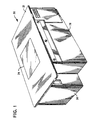
- Fig. 1 there is shown a perspective view of an optical scanner in which the present invention may be incorporated.
- the scanner comprises a box-like structure generally indicated by the numeral 20 and which includes a cover portion 22 having centrally located therein a glass covered aperture 24. While the present invention is disclosed as being incorporated into a portable optical scanner, it is obvious that the invention can be utilized in scanners which are mounted within a checkout counter or in a hand-held scanner for scanning bar code labels.
- the structure 20 includes a pair of side wall portions 26 and 28 (Fig. 2) and front and rear wall portions 30 and 32 (Fig. 2) having a maximum depth of 13 centimeters.
- the structure 20 is normally mounted within a checkout counter (not shown) whose supporting surface is coplanar with the top surface of the cover portion 22 enabling a purchased merchandise item having a UPC coded label attached thereto to be moved past the aperture 24 as part of a checkout operation.
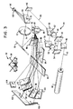
- a shelf member 36 Extending between the side wall portion 28 and an inner side wall portion 34 of the structure 20 is a shelf member 36.
- the inner side wall portion 34 and the side wall portion 26 form a compartment generally indicated by the numeral 38 in which is located a Helium neon laser member 42 secured to the side wall portion 34 which projects a coherent light beam 43 (Fig. 3) through an aperture 44 located in a rear wall portion 46 of the compartment 38.
- a routing mirror 48 Positioned adjacent the aperture 44 and mounted on the shelf member 36 is a routing mirror 48 positioned at a 45° angle to the center line of the aperture 44.
- a beam processing system mounted on the shelf member 36 adjacent the routing mirror 48 and the rear wall portion 32 is a beam processing system generally indicated by the numeral 49 and which includes beam splitter members 50 and 60, routing mirrors 54 and 58 and focusing lens members 56 and 64.
- the beam processing system 49 will split the light beam 43 outputted by the laser member 42 into two secondary beams 52, 62 (Fig. 3) which are focused at different predetermined distances by the focusing lenses 56 and 64 after which the beams are combined to form a single scanning light beam 65.
- a second routing mirror 66 mounted on the shelf member 36 adjacent the beam processing system 49.
- a transparent collection mirror 68 which includes an aperture 70 extending through the mirror 68.
- the mirror 68 has one side 69 constructed to reflect light beams impinging thereon in a manner that is well known in the art.
- a convex lens member 72 which includes an aperture 74 extending through the lens member 72. The lens member 72 is constructed to focus the light beams reflected from a scanned UPC coded label onto a photodetector 110.
- a routing mirror 76 Mounted at an angle of 65° to the shelf member 36 is a routing mirror 76 (Figs. 2 and 3). As will be described more fully hereinafter, the routing mirrors 48 and 66 will direct the output light beam of the laser member 42 through the aperture 70 in the collection mirror 68 and the aperture 74 in the convex lens member 72 to the routing mirror 76 which deflects the light beam in downward direction through the recessed portion 77 in the shelf member 36 to a position beneath the shelf member 36 and the bifocal lens member 72. The deflected light beam impinges on a multifaceted mirrored spinner generally indicated by the numeral 78. The spinner 78 is rotatably mounted on a drive motor 80 (Fig.
- Fig. 3 secured to the lower surface of the shelf member 36 for rotating the spinner 78 at a predetermined speed, for example, 6144 revolutions per minute.
- Fig. 3 Secured to the spinner 78 are six mirror elements 82 (Fig. 3) in which opposite sided mirrors are mounted at various angles to the vertical face of the spinner in order to generate a multiple line scanning pattern as will be described more fully hereinafter.
- Two of the mirrors are pitched backward by 8° to a vertical plane.
- One of the remaining two sets of mirror 82 are pitched forward by 3°, while the remaining set of two mirrors are pitched backward by 3°.
- a center lower pattern mirror 84 Mounted at an angle to the floor portion 81 of the structure 20 is a center lower pattern mirror 84 while secured to brackets (not shown) mounted on the floor portion 81 are a right lower pattern mirror 86 and a left lower pattern mirror 88. Mounted at a slight angle to the floor portion 81 is a center upright pattern mirror 90. Located adjacent the front wall portion 30 of the structure 20 and mounted at an angle of 72° to the floor portion 81 are a right end lower pattern mirror 92 and a left end lower pattern mirror 100. Mounted at an angle of 71° to the floor portion 81 is a right middle lower pattern mirror 94 and a left middle lower pattern mirror 98. Mounted at an angle of 65° to the floor portion 81 is a center pattern mirror 96.
- a center top pattern mirror 102 Mounted to the front wall portion 30 in a direction off-set to a vertical plane by 3°: are a center top pattern mirror 102, a right top pattern mirror 106 orientated 49° to the mirror 102 and a left top pattern mirror 104 orientated 49° to the mirror 102.
- the mirrors 92-100 inclusive are orientated at an angle with respect to the floor portion 81. These mirrors act together with the mirrors 102-106 inclusive to direct the scanning light beams received from the pattern mirrors 84-90 inclusive through the aperture 24 (Fig. 1) to form a scanning pattern generally indicated by the numeral 97 (Fig. 3) which consist of three sets of scan lines 99 for scanning the UPC label positioned adjacent the aperture 24.
- Each set of scan lines is generated by a facet 82 (Figs. 2 and 3) orientated at 8°: to a vertical plane and one of the facets 82 orientated either plus or minus 3°.
- a colored meniscus lens member 108 Located in the side wall portion 28 (Fig. 2) of the enclosure structure 20 is a colored meniscus lens member 108 (Figs. 2 and 3) in which is positioned the photodetector 110 for converting the light beams received from the lens member 108 into electrical signals which are processed by the scanner electronics in a manner that is well known in the art.
- the color of the lens member 108 is chosen to filter out wavelengths of the light beams reflected from the UPC label which are less than that of the laser light beam, such as the blue and green light bands, resulting in the transmission of light beams to the photodetector 110 having a band pass centered on the wavelength of the laser light beam.
- the collection mirror 68 is a spectrally selective "cold" mirror which reflects light beams having a wavelength equal to or less than that of the laser light beam outputted by the laser member 42.
- Side 69 of the mirror 68 is painted with a light absorbing material such as black aluminum which absorbs light having a wavelength greater than that of the laser light beam, such as the infrared band, while reflecting the remaining bands of the reflected light beams.
- FIG. 3 there is shown a perspective view of the optical elements found in the enclosed structure 20 for directing the light beam 43 of the laser member 42 in a direction to generate the scanning pattern 97.
- the laser light beam 43 outputted from the laser 42 is deflected by the routing mirror 48 towards the beam splitter member 50 which splits the beam into a first secondary light beam 52 and a second secondary light beam 62.
- the secondary light beam 52 is directed at the routing mirror 54 which reflects the light beam at the focusing lens 56 which in turn focuses the light beam at a plane (not shown) located at a first predetermined distance from the aperture 24 (Fig. 1).
- the light beam 52 emanating from the focusing lens member 56 is deflected off the routing mirror 58 towards the second beam splitter member 60 which combines the light beams 52 and 62 producing the scanning light beam 65 which in turn is directed towards the routing mirror 66.
- the scanning light beam 65 is composed of two scanning light beams 52 and 62 which will be focused at different focal planes located adjacent the aperture 24.
- the bar code label will modulate only the secondary beam that is focused on that plane.
- the other secondary beam has a diameter too large to be modulated by the bar code label and therefore does not provide a signal. This process is repeated as the bar code label is located at different planes adjacent the aperture 24.
- the scanning light beam 65 is comprised of secondary beams originating from the same source. This arrangement can be repeated for multiple beams superimposed on each other.
- the scanning light beam 65 reflected by the routing mirror 66 is directed through the aperture 70 in the collection mirror 68 and through the aperture 74 of the convex lens member 72 to the mirror 76 which reflects the light beam towards the rotating mirrored spinner 78.
- the light beam 65 upon striking the various facets 82 of the spinner 78, will be deflected to the pattern mirrors 84-90 inclusive.
- the mirrors 84-90 inclusive will reflect the received light beams towards the mirrors 92-106 inclusive which in turn deflect the light beams through the aperture 24 (Fig. 1) in the cover portion 22 of the structure 20.
- the scanning pattern 97 that is generated by this mirror system comprises sets of scan lines 99 which cross, as shown in Fig. 3, to provide a highly efficient scanning pattern capable of reading a bar code label orientated up to 90° to the cover portion 22.
- the diverging reflected light beams are retrodirected through the aperture 24 to the pattern mirrors 84-106 inclusive and to the spinner 78 which direct the reflective light beams towards the routing mirror 76 from where the light beams are directed to the convex lens member 72.
- the lens member 72 will focus the received light beams at the photodetector 110 by directing the reflected light beams towards the collection mirror 68 which reflects the received light beams towards the lens member 108 from where the photodetector 110 will generate electrical signals,for use in processing the data incorporated in the bar code label.
- the reflected light beams may contain sunlight
- the mirror 68 and the lens member 108 will filter out all wavelengths of light except that of the laser light beam thus ensuring that the light beams received by the photodetector 110 will enable the photodetector to generate electrical signals which accurately represent the data contained in the bar code label.
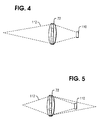
- the light beams 112 reflected from a bar code label positioned in the farthest focal plane will be focused by the lens member 72 completely on the photodetector 110 while the light beams reflected from a bar code label positioned in the nearest focal plane (Fig. 5) will overfill the photodetector thus limiting the amount of reflected light beams that is impinging on the photodetector.
- This arrangement provides an automatic dynamic range control of the light energy transmitted to the photodetector as the distance between the bar code label and the scanning unit is varied.
- the scanning light beam 65 which generates the scanning lines 99 comprising the scanning pattern 97 will contain a plurality of scanning light beams each of which is focused at a different focal point to read a bar code label enabling the scanner to scan bar code labels which are moved through different focal planes adjacent the aperture 24 of the scanner.
- This construction enables the scanner to provide a higher rate of valid read operations of the bar code label.
- the source can be either a laser of the type mentioned hereinabove or any other type of source of light that can be collimated and conditioned, such as a Visible Laser Diode or a high powered LED.
Landscapes
- Physics & Mathematics (AREA)
- Electromagnetism (AREA)
- Engineering & Computer Science (AREA)
- Health & Medical Sciences (AREA)
- General Health & Medical Sciences (AREA)
- Toxicology (AREA)
- Artificial Intelligence (AREA)
- Computer Vision & Pattern Recognition (AREA)
- General Physics & Mathematics (AREA)
- Theoretical Computer Science (AREA)
- Mechanical Optical Scanning Systems (AREA)
- Cash Registers Or Receiving Machines (AREA)
Claims (6)
- Optisches Abtastgerät zum Abtasten von auf Gegenständen befindlichen verschlüsselten Zeichen, mit einer Lichtstrahlabgabeeinrichtung (42, 48, 50, 54), die zur Lieferung einer Vielzahl von Lichtstrahlen (52, 62) geeignet ist; einer Vielzahl von Fokussiereinrichtungen (56, 64), die zum Auffangen einzelner dieser Lichtstrahlen (52, 62) und Fokussieren der aufgefangenen Lichtstrahlen (52, 62) an einzelnen unterteilten Brennebenen geeignet sind; einer Strahlenvereinigungseinrichtung (60), die geeignet ist, die fokussierten Lichtstrahlen zur Lieferung eines einzigen Lichtstrahls (65) zu vereinen; und Strahlablenkeinrichtungen (66, 78 - 106), die geeignet sind, den Einzellichtstrahl (65) zur Bildung eines zur Abtastung der verschlüsselten Zeichen geeigneten Abtastmusters (97) abzulenken,
dadurch gekennzeichnet, daß
die Lichtstrahlabgabeeinrichtung eine Einzellichtstrahlquelle aufweist, die geeignet ist, einen ersten Lichtstrahl (43) zu liefern, der eine erste Bahn entlanggerichtet ist und Strahlteilungsmittel (50), die in der ersten Bahn angeordnet und geeignet sind, den ersten Lichtstrahl (43) in einen zweiten und dritten Lichtstrahl (52, 62) zu teilen, die eine entsprechende zweite und dritte Bahn entlanggerichtet sind; und daß die Vielzahl von Fokussiereinrichtungen eine erste und eine zweite Fokussiervorrichtung (56, 64) beinhaltet, die in der zweiten bzw. dritten Bahn angebracht sind. - Optisches Abtastgerät nach Anspruch 1, dadurch gekennzeichnet, daß die dritte Bahn (62) in Linie mit der ersten Bahn ist und die zweite Bahn einen ersten Abschnitt im rechten Winkel zu der ersten Bahn und einen zweiten Abschnitt parallel zu der dritten Bahn aufweist, und die erste Fokussiervorrichtung (56) und einen dritten Abschnitt enthält, der parallel zu dem ersten Abschnitt und auf die Strahlenvereinigungseinrichtungen (58, 60) zu gerichtet ist.
- Optisches Abtastgerät nach Anspruch 2, dadurch gekennzeichnet, daß die Strahlenvereinigungseinrichtung geeignet ist, den dem dritten Abschnitt entlanggerichteten ersten Lichtstrahl (52) und den der dritten Bahn entlanggerichteten zweiten Lichtstrahl (62) zu dem einzigen Abtastlichtstrahl (65) zu vereinen, der eine vierte Bahn in Linie mit der zweiten Bahn entlanggerichtet ist.
- Optisches Abtastgerät nach einem der Ansprüche 1 bis 3, dadurch gekennzeichnet, daß die Lichtstrahlquelle ein Helium-Neon-Laser ist.
- Optisches Abtastgerät nach einem der vorhergehenden Ansprüche, dadurch gekennzeichnet, daß die Ablenkeinrichtung ein Abtasterelement (78, 80, 82) aufweist, das geeignet ist, den Einzellichtstrahl (65) über eine Vielzahl von Abtastbahnen hinwegstreichen zu lassen und Reflexionsmittel (84 - 106), die geeignet sind, die Abtastbahnen in einen Abtastbereich abzulenken, in dem das Abtastmuster (97) erzeugt wird.
- Optisches Abtastgerät nach Anspruch 5, dadurch gekennzeichnet, daß der Einzellichtstrahl (65) ein Sammellinsenelement (72) passiert, das geeignet ist, reflektiertes Licht von einem durch das Abtastmuster (97) abgetasteten Gegenstand zu sammeln und das reflektierte Licht auf eine Detektoreinrichtung (110) zu fokussieren.
Applications Claiming Priority (2)
| Application Number | Priority Date | Filing Date | Title |
|---|---|---|---|
| US498887 | 1990-03-26 | ||
| US07/498,887 US5073702A (en) | 1990-03-26 | 1990-03-26 | Multiple beam bar code scanner |
Publications (2)
| Publication Number | Publication Date |
|---|---|
| EP0449490A1 EP0449490A1 (de) | 1991-10-02 |
| EP0449490B1 true EP0449490B1 (de) | 1996-12-04 |
Family
ID=23982912
Family Applications (1)
| Application Number | Title | Priority Date | Filing Date |
|---|---|---|---|
| EP91302400A Expired - Lifetime EP0449490B1 (de) | 1990-03-26 | 1991-03-20 | Optisches Abtastgerät |
Country Status (4)
| Country | Link |
|---|---|
| US (1) | US5073702A (de) |
| EP (1) | EP0449490B1 (de) |
| JP (1) | JPH04223582A (de) |
| DE (1) | DE69123381T2 (de) |
Families Citing this family (54)
| Publication number | Priority date | Publication date | Assignee | Title |
|---|---|---|---|---|
| US5254844A (en) * | 1988-05-11 | 1993-10-19 | Symbol Technologies, Inc. | Mirrorless scanners with movable laser, optical and sensor components |
| US5128520A (en) | 1989-08-11 | 1992-07-07 | Spectra-Physics, Inc. | Scanner with coupon validation |
| US5206491A (en) * | 1990-03-02 | 1993-04-27 | Fujitsu Limited | Plural beam, plural window multi-direction bar code reading device |
| US5258605A (en) * | 1990-03-13 | 1993-11-02 | Symbol Technologies, Inc. | Scan generators for bar code reader using linear array of lasers |
| US5216232A (en) * | 1990-09-10 | 1993-06-01 | Metrologic Instruments, Inc. | Projection laser scanner producing a narrow scan volume |
| US5796091A (en) * | 1993-11-24 | 1998-08-18 | Metrologic Instruments, Inc. | Automatic hand-supportable omnidirectional laser projection scanner with handle-controllable projection axis |
| US5081364A (en) * | 1990-11-26 | 1992-01-14 | Ncr Corporation | Multifocal scanning system |
| US5210398A (en) * | 1991-06-14 | 1993-05-11 | Symbol Technologies, Inc. | Optical scanner with extended depth of focus |
| CA2056272C (en) * | 1991-06-14 | 2001-10-16 | Patrick Salatto, Jr. | Combined range laser scanner |
| US5491328A (en) * | 1991-09-24 | 1996-02-13 | Spectra-Physics Scanning Systems, Inc. | Checkout counter scanner having multiple scanning surfaces |
| US5438187A (en) * | 1991-11-01 | 1995-08-01 | Spectra-Physics Scanning Systems, Inc. | Multiple focus optical system for data reading applications |
| JP2789282B2 (ja) * | 1992-07-10 | 1998-08-20 | 富士通株式会社 | 光学式マーク読取装置 |
| US5475207A (en) * | 1992-07-14 | 1995-12-12 | Spectra-Physics Scanning Systems, Inc. | Multiple plane scanning system for data reading applications |
| US5410108A (en) * | 1992-08-31 | 1995-04-25 | Spectra-Physics Scanning Systems, Inc. | Combined scanner and scale |
| US5361158A (en) * | 1992-09-14 | 1994-11-01 | At&T Global Information Solutions (Fka Ncr Corporation) | Multiple source optical scanner |
| US5347121A (en) * | 1992-12-18 | 1994-09-13 | Spectra-Physics Scanning Systems, Inc. | Variable focus optical system for data reading |
| US5479011A (en) * | 1992-12-18 | 1995-12-26 | Spectra-Physics Scanning Systems, Inc. | Variable focus optical system for data reading |
| US5498862A (en) * | 1993-05-06 | 1996-03-12 | International Computers Limited | Side scanning bar code reader with vertical and horizontal scan patterns |
| US5404002A (en) * | 1993-05-17 | 1995-04-04 | At&T Global Information Solutions Company | Backup method for multiple source optical scanner |
| DE4441298B8 (de) * | 1993-11-19 | 2005-01-13 | Psc Scanning Inc. (N.D.Ges.D. Staates Delaware), Eugene | Mehrebenen-Abtastsystem für das Lesen von Daten |
| US5767501A (en) * | 1993-11-24 | 1998-06-16 | Metrologic Instruments, Inc. | Mass-balanced automatic hand-supportable laser projection scanner for fatigue-free omnidirectional scanning of bar code symbols |
| NL9401302A (nl) * | 1994-08-11 | 1996-03-01 | Scantech Bv | Barcode scanner. |
| US7051922B2 (en) * | 1994-08-17 | 2006-05-30 | Metrologic Instruments, Inc. | Compact bioptical laser scanning system |
| US6758402B1 (en) * | 1994-08-17 | 2004-07-06 | Metrologic Instruments, Inc. | Bioptical holographic laser scanning system |
| JPH0991368A (ja) * | 1995-07-20 | 1997-04-04 | Fujitsu Ltd | 光学読取装置 |
| JPH08335243A (ja) * | 1995-06-08 | 1996-12-17 | Fujitsu Ltd | バーコードスキャナ |
| US5834708A (en) | 1995-06-08 | 1998-11-10 | Spectra-Physics Scanning Systems, Inc. | Multiple plane weigh platter for multiple plane scanning systems |
| US5979767A (en) * | 1995-08-11 | 1999-11-09 | Scantech B.V. | Portable multi-directional bar code scanner |
| JP3441580B2 (ja) | 1995-12-14 | 2003-09-02 | 富士通株式会社 | 読取装置 |
| US6575368B1 (en) | 1996-01-31 | 2003-06-10 | Psc Scanning, Inc. | Multiple aperture data reader for multi-mode operation |
| US6260763B1 (en) * | 1996-02-06 | 2001-07-17 | Psc Scanning, Inc. | Integral illumination source/collection lens assembly for data reading system |
| JP3881792B2 (ja) | 1998-10-21 | 2007-02-14 | 富士通株式会社 | 光走査装置、コード読取装置およびバーコード読取装置 |
| US6542304B2 (en) | 1999-05-17 | 2003-04-01 | Toolz, Ltd. | Laser beam device with apertured reflective element |
| US20030132291A1 (en) * | 2002-01-11 | 2003-07-17 | Metrologic Instruments, Inc. | Point of sale (POS) station having bar code reading system with integrated internet-enabled customer-kiosk terminal |
| US6918540B2 (en) * | 2000-04-18 | 2005-07-19 | Metrologic Instruments, Inc. | Bioptical point-of-sale (pos) scanning system employing dual polygon-based laser scanning platforms disposed beneath horizontal and vertical scanning windows for 360° omni-directional bar code scanning |
| US7100832B2 (en) * | 2000-04-18 | 2006-09-05 | Metrologic Instruments, Inc. | Bioptical laser scanning system providing 360° of omnidirectional bar code symbol scanning coverage at point of sale station |
| JP4330762B2 (ja) | 2000-04-21 | 2009-09-16 | 富士フイルム株式会社 | マルチビーム露光装置 |
| US6390369B1 (en) * | 2001-02-23 | 2002-05-21 | Ncr Corporation | Streamlined scanner spinner |
| US7296748B2 (en) * | 2002-01-11 | 2007-11-20 | Metrologic Instruments, Inc. | Bioptical laser scanning system providing 360° of omnidirectional bar code symbol scanning coverage at point of sale station |
| US6874690B2 (en) * | 2002-01-11 | 2005-04-05 | Metrologic Instruments, Inc. | Modular omnidirectional bar code symbol scanning system with at least one service port for removable installation of scan module insert |
| US7083102B2 (en) * | 2002-01-11 | 2006-08-01 | Metrologic Instruments, Inc. | Bioptical laser scanner for six-sided 360° Pos-based scanning |
| JP4402642B2 (ja) * | 2005-11-30 | 2010-01-20 | 富士通株式会社 | 読取装置および読取方法 |
| EP2030067B1 (de) | 2006-06-20 | 2023-05-31 | Datalogic USA, Inc. | Abbildungsscanner mit mehreren bildfeldern |
| EP2248069B1 (de) | 2008-02-12 | 2013-08-28 | Datalogic ADC, Inc. | Systeme und verfahren zur herstellung eines zusammengesetzten bildes mit mehreren teilen eines objekts aus mehreren perspektiven |
| US8353457B2 (en) | 2008-02-12 | 2013-01-15 | Datalogic ADC, Inc. | Systems and methods for forming a composite image of multiple portions of an object from multiple perspectives |
| US8678287B2 (en) | 2008-02-12 | 2014-03-25 | Datalogic ADC, Inc. | Two-plane optical code reader for acquisition of multiple views of an object |
| US8608076B2 (en) | 2008-02-12 | 2013-12-17 | Datalogic ADC, Inc. | Monolithic mirror structure for use in a multi-perspective optical code reader |
| US20100155482A1 (en) * | 2008-12-23 | 2010-06-24 | Ncr Corporation | Methods and Apparatus for Increased Range of Focus in Image Based Bar Code Scanning |
| US8322621B2 (en) | 2008-12-26 | 2012-12-04 | Datalogic ADC, Inc. | Image-based code reader for acquisition of multiple views of an object and methods for employing same |
| US8261990B2 (en) | 2008-12-26 | 2012-09-11 | Datalogic ADC, Inc. | Data reader having compact arrangement for acquisition of multiple views of an object |
| US8496178B2 (en) * | 2011-08-31 | 2013-07-30 | Ncr Corporation | Method and apparatus for providing customer side imaging as well as bar code scanning imaging |
| US8523076B2 (en) | 2012-01-10 | 2013-09-03 | Metrologic Instruments, Inc. | Omnidirectional laser scanning bar code symbol reader generating a laser scanning pattern with a highly non-uniform scan density with respect to line orientation |
| USD730901S1 (en) * | 2014-06-24 | 2015-06-02 | Hand Held Products, Inc. | In-counter barcode scanner |
| TWI701517B (zh) * | 2014-12-23 | 2020-08-11 | 德商卡爾蔡司Smt有限公司 | 光學構件 |
Family Cites Families (18)
| Publication number | Priority date | Publication date | Assignee | Title |
|---|---|---|---|---|
| US3524706A (en) * | 1966-06-10 | 1970-08-18 | Pan American Petroleum Corp | Method and apparatus for optically processing seismic data using spatial filtering techniques |
| GB1266916A (de) * | 1968-04-25 | 1972-03-15 | ||
| DE1915680B2 (de) * | 1969-03-27 | 1973-03-08 | Ernst Leitz Gmbh, 6330 Wetzlar | Fotometer fuer beobachtungsinstrumente, insbesondere mikroskope |
| US3708797A (en) * | 1971-09-24 | 1973-01-02 | Columbia Broadcasting Syst Inc | Multi-channel laser recording system |
| US3818444A (en) * | 1972-06-29 | 1974-06-18 | Pitney Bowes Inc | Optical bar code reading method and apparatus having an x scan pattern |
| US3928759A (en) * | 1974-08-22 | 1975-12-23 | Pitney Bowes Inc | Omnidirectional scanner for reading digitally encoded tickets |
| DE2634243A1 (de) * | 1976-07-30 | 1978-02-02 | Bosch Gmbh Robert | System zur aufzeichnung und/oder wiedergabe von signalen mittels strahlen |
| US4224509A (en) * | 1978-10-19 | 1980-09-23 | Ncr Corporation | Holographic scanning system |
| US4333906A (en) * | 1979-03-12 | 1982-06-08 | Extracorporeal Medical Specialties, Inc. | Process for producing hollow fibers having a non-uniform wall thickness and a non-uniform cross-sectional area |
| AU535350B2 (en) * | 1979-05-07 | 1984-03-15 | Sony Corporation | Inline hologram lens |
| DE2925734C3 (de) * | 1979-06-26 | 1982-06-24 | Erwin Sick Gmbh Optik-Elektronik, 7808 Waldkirch | Optisches Fehlersuchgerät für Materialbahnen |
| JPS5969979A (ja) * | 1982-10-15 | 1984-04-20 | Hitachi Ltd | レ−ザ光源装置 |
| US4560862A (en) * | 1983-04-26 | 1985-12-24 | Skan-A-Matic Corp. | System for optical scanning over a large depth of field |
| US4591242A (en) * | 1984-02-13 | 1986-05-27 | International Business Machines Corp. | Optical scanner having multiple, simultaneous scan lines with different focal lengths |
| US4738499A (en) * | 1985-06-12 | 1988-04-19 | Mitsubishi Denki Kabushiki Kaisha | Stationary hologram scanner |
| US4794237A (en) * | 1986-11-10 | 1988-12-27 | Ncr Corporation | Multidirectional holographic scanner |
| US4797551A (en) * | 1987-06-11 | 1989-01-10 | Ncr Corporation | Compact laser scanner optical system |
| KR910008421B1 (ko) * | 1988-05-24 | 1991-10-15 | 주식회사 금성사 | 홀로그램 스캐너를 이용한 바코드리더의 바코드 검지방법 및 주사광학계 |
-
1990
- 1990-03-26 US US07/498,887 patent/US5073702A/en not_active Expired - Lifetime
-
1991
- 1991-03-20 DE DE69123381T patent/DE69123381T2/de not_active Expired - Lifetime
- 1991-03-20 EP EP91302400A patent/EP0449490B1/de not_active Expired - Lifetime
- 1991-03-20 JP JP3080624A patent/JPH04223582A/ja active Pending
Also Published As
| Publication number | Publication date |
|---|---|
| EP0449490A1 (de) | 1991-10-02 |
| US5073702A (en) | 1991-12-17 |
| DE69123381T2 (de) | 1997-08-28 |
| JPH04223582A (ja) | 1992-08-13 |
| DE69123381D1 (de) | 1997-01-16 |
Similar Documents
| Publication | Publication Date | Title |
|---|---|---|
| EP0449490B1 (de) | Optisches Abtastgerät | |
| US6460767B1 (en) | Optical scanner for omni-directional scanning of code symbols within a scanning volume | |
| EP0318574B1 (de) | Optisches ablesegerät | |
| US5801370A (en) | Multi-directional bar code reading device | |
| EP0295936B1 (de) | Anordnung zur Erzeugung eines optischen Abtastrasters für Laserabtaster | |
| US5859417A (en) | Optical scanners having dual surface optical elements for dual working ranges | |
| US4851667A (en) | Compact laser scanner optical system | |
| CA2580841C (en) | System and method for reading optically encoded information | |
| JPH0132550B2 (de) | ||
| JPH0628508A (ja) | 光学読取方法および光学読取装置 | |
| US4025761A (en) | Optical system for code symbol scanners | |
| EP0396485B1 (de) | Strichkodeleser mit grosser Schärfentiefe | |
| US6412696B1 (en) | Countertop projection laser scanning system for omnidirectional scanning of code symbols within a narrowly-confined scanning volume projected above a countertop surface | |
| US5179271A (en) | Compact optical scan pattern generator for bar code reading systems | |
| US5498862A (en) | Side scanning bar code reader with vertical and horizontal scan patterns | |
| US5192857A (en) | Compact optical scanner rotatable between horizontal and vertical positions | |
| US20010017320A1 (en) | Projection laser scanner for scanning bar codes within a confined scanning volume | |
| JPH0823629B2 (ja) | 光学読取装置 | |
| US5081364A (en) | Multifocal scanning system | |
| US5043563A (en) | Portable overhead bar code scanner | |
| EP0533366A2 (de) | Gerät und Verfahren für optisches Abtasten | |
| EP0533383A2 (de) | Optische Abtastvorrichtung | |
| EP0532220B1 (de) | Barcodeleser und seine Wirkungsweise | |
| EP0528630A2 (de) | Optisches Abtastgerät | |
| JP2889754B2 (ja) | 光走査装置 |
Legal Events
| Date | Code | Title | Description |
|---|---|---|---|
| PUAI | Public reference made under article 153(3) epc to a published international application that has entered the european phase |
Free format text: ORIGINAL CODE: 0009012 |
|
| AK | Designated contracting states |
Kind code of ref document: A1 Designated state(s): DE FR GB |
|
| 17P | Request for examination filed |
Effective date: 19920312 |
|
| RAP1 | Party data changed (applicant data changed or rights of an application transferred) |
Owner name: NCR INTERNATIONAL INC. |
|
| RAP1 | Party data changed (applicant data changed or rights of an application transferred) |
Owner name: AT&T GLOBAL INFORMATION SOLUTIONS INTERNATIONAL IN |
|
| 17Q | First examination report despatched |
Effective date: 19941229 |
|
| GRAG | Despatch of communication of intention to grant |
Free format text: ORIGINAL CODE: EPIDOS AGRA |
|
| GRAH | Despatch of communication of intention to grant a patent |
Free format text: ORIGINAL CODE: EPIDOS IGRA |
|
| RAP1 | Party data changed (applicant data changed or rights of an application transferred) |
Owner name: NCR INTERNATIONAL, INC. |
|
| GRAH | Despatch of communication of intention to grant a patent |
Free format text: ORIGINAL CODE: EPIDOS IGRA |
|
| GRAA | (expected) grant |
Free format text: ORIGINAL CODE: 0009210 |
|
| AK | Designated contracting states |
Kind code of ref document: B1 Designated state(s): DE FR GB |
|
| REF | Corresponds to: |
Ref document number: 69123381 Country of ref document: DE Date of ref document: 19970116 |
|
| ET | Fr: translation filed | ||
| PLBE | No opposition filed within time limit |
Free format text: ORIGINAL CODE: 0009261 |
|
| STAA | Information on the status of an ep patent application or granted ep patent |
Free format text: STATUS: NO OPPOSITION FILED WITHIN TIME LIMIT |
|
| 26N | No opposition filed | ||
| REG | Reference to a national code |
Ref country code: GB Ref legal event code: IF02 |
|
| PGFP | Annual fee paid to national office [announced via postgrant information from national office to epo] |
Ref country code: FR Payment date: 20100210 Year of fee payment: 20 |
|
| PGFP | Annual fee paid to national office [announced via postgrant information from national office to epo] |
Ref country code: GB Payment date: 20100205 Year of fee payment: 20 |
|
| PGFP | Annual fee paid to national office [announced via postgrant information from national office to epo] |
Ref country code: DE Payment date: 20100226 Year of fee payment: 20 |
|
| REG | Reference to a national code |
Ref country code: DE Ref legal event code: R071 Ref document number: 69123381 Country of ref document: DE |
|
| REG | Reference to a national code |
Ref country code: GB Ref legal event code: PE20 Expiry date: 20110319 |
|
| PG25 | Lapsed in a contracting state [announced via postgrant information from national office to epo] |
Ref country code: GB Free format text: LAPSE BECAUSE OF EXPIRATION OF PROTECTION Effective date: 20110319 |
|
| PG25 | Lapsed in a contracting state [announced via postgrant information from national office to epo] |
Ref country code: DE Free format text: LAPSE BECAUSE OF EXPIRATION OF PROTECTION Effective date: 20110320 |