EP0449480B1 - Routage en temps réel dans un réseau - Google Patents
Routage en temps réel dans un réseau Download PDFInfo
- Publication number
- EP0449480B1 EP0449480B1 EP91302321A EP91302321A EP0449480B1 EP 0449480 B1 EP0449480 B1 EP 0449480B1 EP 91302321 A EP91302321 A EP 91302321A EP 91302321 A EP91302321 A EP 91302321A EP 0449480 B1 EP0449480 B1 EP 0449480B1
- Authority
- EP
- European Patent Office
- Prior art keywords
- service
- group
- load
- available
- call
- Prior art date
- Legal status (The legal status is an assumption and is not a legal conclusion. Google has not performed a legal analysis and makes no representation as to the accuracy of the status listed.)
- Expired - Lifetime
Links
- 238000000034 method Methods 0.000 claims description 30
- 238000013519 translation Methods 0.000 claims description 2
- 230000009471 action Effects 0.000 description 135
- 230000005540 biological transmission Effects 0.000 description 97
- 238000012360 testing method Methods 0.000 description 75
- 230000000903 blocking effect Effects 0.000 description 35
- 230000004044 response Effects 0.000 description 26
- 241000233805 Phoenix Species 0.000 description 13
- 238000010586 diagram Methods 0.000 description 13
- 238000005259 measurement Methods 0.000 description 10
- 230000008569 process Effects 0.000 description 8
- 230000008859 change Effects 0.000 description 7
- 230000000694 effects Effects 0.000 description 6
- 108091006146 Channels Proteins 0.000 description 5
- 238000004088 simulation Methods 0.000 description 5
- 230000011664 signaling Effects 0.000 description 4
- 238000013459 approach Methods 0.000 description 3
- 238000004891 communication Methods 0.000 description 3
- 230000000737 periodic effect Effects 0.000 description 2
- 241000196324 Embryophyta Species 0.000 description 1
- 230000003044 adaptive effect Effects 0.000 description 1
- 230000002730 additional effect Effects 0.000 description 1
- 238000012937 correction Methods 0.000 description 1
- 230000001186 cumulative effect Effects 0.000 description 1
- 230000002349 favourable effect Effects 0.000 description 1
- 230000006870 function Effects 0.000 description 1
- 238000012545 processing Methods 0.000 description 1
- 238000011084 recovery Methods 0.000 description 1
Images


Classifications
-
- H—ELECTRICITY
- H04—ELECTRIC COMMUNICATION TECHNIQUE
- H04Q—SELECTING
- H04Q3/00—Selecting arrangements
- H04Q3/0016—Arrangements providing connection between exchanges
-
- H—ELECTRICITY
- H04—ELECTRIC COMMUNICATION TECHNIQUE
- H04Q—SELECTING
- H04Q3/00—Selecting arrangements
- H04Q3/64—Distributing or queueing
- H04Q3/66—Traffic distributors
-
- H—ELECTRICITY
- H04—ELECTRIC COMMUNICATION TECHNIQUE
- H04Q—SELECTING
- H04Q2213/00—Indexing scheme relating to selecting arrangements in general and for multiplex systems
- H04Q2213/13138—Least cost routing, LCR
-
- H—ELECTRICITY
- H04—ELECTRIC COMMUNICATION TECHNIQUE
- H04Q—SELECTING
- H04Q2213/00—Indexing scheme relating to selecting arrangements in general and for multiplex systems
- H04Q2213/13141—Hunting for free outlet, circuit or channel
-
- H—ELECTRICITY
- H04—ELECTRIC COMMUNICATION TECHNIQUE
- H04Q—SELECTING
- H04Q2213/00—Indexing scheme relating to selecting arrangements in general and for multiplex systems
- H04Q2213/13148—Maximum profit routing
-
- H—ELECTRICITY
- H04—ELECTRIC COMMUNICATION TECHNIQUE
- H04Q—SELECTING
- H04Q2213/00—Indexing scheme relating to selecting arrangements in general and for multiplex systems
- H04Q2213/13164—Traffic (registration, measurement,...)
-
- H—ELECTRICITY
- H04—ELECTRIC COMMUNICATION TECHNIQUE
- H04Q—SELECTING
- H04Q2213/00—Indexing scheme relating to selecting arrangements in general and for multiplex systems
- H04Q2213/13166—Fault prevention
-
- H—ELECTRICITY
- H04—ELECTRIC COMMUNICATION TECHNIQUE
- H04Q—SELECTING
- H04Q2213/00—Indexing scheme relating to selecting arrangements in general and for multiplex systems
- H04Q2213/13332—Broadband, CATV, dynamic bandwidth allocation
-
- H—ELECTRICITY
- H04—ELECTRIC COMMUNICATION TECHNIQUE
- H04Q—SELECTING
- H04Q2213/00—Indexing scheme relating to selecting arrangements in general and for multiplex systems
- H04Q2213/13344—Overflow
-
- H—ELECTRICITY
- H04—ELECTRIC COMMUNICATION TECHNIQUE
- H04Q—SELECTING
- H04Q2213/00—Indexing scheme relating to selecting arrangements in general and for multiplex systems
- H04Q2213/13349—Network management
-
- H—ELECTRICITY
- H04—ELECTRIC COMMUNICATION TECHNIQUE
- H04Q—SELECTING
- H04Q2213/00—Indexing scheme relating to selecting arrangements in general and for multiplex systems
- H04Q2213/13353—Routing table, map memory
-
- H—ELECTRICITY
- H04—ELECTRIC COMMUNICATION TECHNIQUE
- H04Q—SELECTING
- H04Q2213/00—Indexing scheme relating to selecting arrangements in general and for multiplex systems
- H04Q2213/1338—Inter-exchange connection
Definitions
- This invention relates to methods of selecting an available telecommunications circuit for a service for a call to a destination in a system providing a plurality of services, and to apparatus in a first telecommunications switching system for serving a plurality of different service types of calls, the apparatus being for determining a group through a telecommunications network for serving a call having a given type of service.
- DNHR dynamic non-hierarchical routing
- each switching system is equipped to translate from a received directory number to find a corresponding destination switch.
- Each switch is further equipped to translate from the identity of the destination switching system to an ordered set of up to 14 direct (i.e., without using an intermediate switching system), or alternate routes for reaching this switching system.
- Each switching system is further equipped with 16 sets of alternate routing tables in order to allow different routing choices to be used for handling the different characteristics of the call traffic at different hours of the day or days of the week.
- the routing tables are typically updated approximately once per week from information collected at a central operation support system, an integrated routing administration system.
- each switching system transmits circuit occupancy, and out of service data, and call loads to a centralized network management system every five minutes or even more frequently, to allow a centralized network management system to respond to special conditions such as temporary overloads of facilities or equipment outages.
- a problem that is encountered in obtaining optimum use of communication facilities is the following:
- trunks connecting two switching systems When a telecommunications network supports different types of services, it is desirable to ensure that an adequate number of trunks are available for each type of service. For example, if the trunks connecting two switching systems are used for carrying both voice and data traffic, it is desirable that a minimum number of the trunks between these two switches be available for carrying voice traffic, and that another minimum number of trunks between these two switches be available for carrying data traffic. It is also desirable that a minimum number of the trunks between these two switches be available for carrying traffic that originates at one of the switches, and that a different minimum number of the trunks between these two switches be available for carrying traffic that originates at the other of the two switches.
- trunk groups are sometimes assigned to be one way groups, only able to carry traffic that originates at one of the switches connected by the group. Such arrangements have the limitation that the trunks are not used as efficiently as they might be. For example, if most of the data trunks are available and the voice traffic is experiencing a peak, many available trunks dedicated to data traffic are unavailable for voice traffic. To change the number of trunks available to each of the services in response to a change in the forecasted loads for these services requires that the assignment of trunks to the different trunk groups be modified. This arrangement is a slow and costly process.
- a general problem of the prior art is that when trunk groups for carrying a plurality of different types of traffic are used to interconnect the switching systems of the telecommunications network, and when it is desired to maintain a minimum objective level of traffic availability for each of these different types of traffic, the present arrangements lead to a less than optimum utilization of the trunk plant interconnecting these switching systems: additionally, there is not a fast, efficient way to change the minimum objective level of traffic availability for each of these different types of services as traffic patterns change over time.
- European patent application EP-A-0376556 discloses arrangements for determining which of a plurality of trunk groups should be used for serving a call.
- a route is composed of no more than two links each link consisting of one or more trunk groups joining two nodes of a switching network.
- destination node After the destination node for a call has been determined that destination node is queried to determine the load state of links from the destination switching system to intermediate switching systems.
- the originating switching system makes a similar determination.
- the originating system After receiving data from the terminating switching system describing the load state of that system's various trunk groups, the originating system compares its link load data with the load data of the links connected to the terminating switch and the two link route having the most favourable load state (i.e. least heavily loaded) is selected for serving a call.
- a trunk group By having trunk groups in a telecommunications network used as the primary, or first-choice, route for a plurality of different types of telecommunications traffic, a trunk group can be the first choice route for calls destined for the switch directly connected by the trunk group, as well as for calls destined for other switches in the network, which subtend the switch directly connected by the trunk group. Calls to any of these switches can be further separated by the various service types supported by the network, e.g., voice calls, data calls, calls that are free to the caller, etc., so that calls destined to a particular switch for a given service type are classified as a unique traffic parcel. Call completion objectives can be specified for each traffic parcel.
- trunks usable for two or more traffic parcels can be reserved for one type of traffic parcel whenever the current completed load for that traffic parcel is below the call objective for that traffic parcel.
- An idle trunk in the trunk group is usable for a new call attempt for a particular traffic parcel if the current completed load for that traffic parcel is below the call objective for that traffic parcel, or if the present number of available trunks in the group is above a threshold of the number of trunks in the trunk group being reserved for other traffic parcels.
- Two or more different thresholds may be provided for the number of trunks that must be available before various services are allowed to use an available trunk in a particular trunk group.
- a lower threshold is provided to maintain traffic capacity for key services that are below their respective objective loads; key services are services for which it is particularly desirable to maintain capacity to meet the call load objectives.
- a higher threshold is provided to maintain traffic capacity for all services which are below their respective objective loads.
- this type of arrangement provides the flexibility for ensuring that call objectives for the particular types of services which are considered to be key services, are maintained, even in the presence of unusual traffic conditions or partial trunk outages.
- a type of service which is considered to be a key service is allowed to seize an available trunk in a route whenever the current carried load for that service is less than the objective level for that service.
- a type of service which is considered to be a standard service is allowed to seize an available trunk in a route whenever the current carried load for that service is less than the objective level for that service, and if the number of available trunks in the route is greater than a parameter set for that route, called the key reserve threshold. If the current carried load is equal to or greater than the objective load for a service, then an available trunk in a route may be seized only if the number of available trunks in the route is greater than another parameter set for that route, known as the total reserve threshold.
- the key reserve threshold for a route is the difference between the actual load carried and the load objective for that type of service summed over all key services which use this route as their primary route.
- the total reserve threshold for a route is the sum of all positive differences between the load objective and the actual carried load for each of the services, including both standard and key services, which use this route as their primary route.
- the number of trunks reserved for a particular service is limited to a reserve limit for that service.
- the reserve parameter for a particular service is the minimum of two numbers, the positive difference, if any, between the objective and the carried load for that service, and the reserve limit for the service. If the carried load equals or exceeds the objective load for a service, then the reserve parameter for that type of traffic is 0.
- a trunk When a trunk group is being used for an alternate route, a trunk may be seized only if the number of available trunks in that group exceeds the total reserve threshold for that trunk group.
- Trunk capacity that has been allocated for a particular service, or for incoming traffic from another switch, which is not being used up by the current traffic loads, is made available for use by other services which are seeing call attempt loads greater than their forecasted load objectives, so trunks between two switches are used much more efficiently. If trunks are taken out of service or are otherwise made unavailable, then key services are given preference for the remaining capacity in the group until they reach their load objectives.
- the trunk groups can be administered as single entities and a simple change of one parameter can be used to adjust for changes in traffic patterns in recognition for a need for a different load objective for a particular type of traffic.
- Trunks may be added or subtracted independently of changing the load objective numbers for each traffic type.
- RTNR is an adaptive routing scheme.
- ASW originating or access switch
- DSW terminating or destination switch
- the ASW will try to set up this call on a direct route to the DSW first. To do this, the ASW simply checks if it has any available 1-way outgoing or 2-way communication paths or trunks to the DSW; if so, the ASW will set up the call on a direct trunk to the DSW.
- This particular mode being part of the prior art, is not shown in any of the illustrative routing diagrams but is shown in the flow diagrams.
- the ASW will determine a route by trying to find an available 2-link path through the network to the DSW. In fact, the ASW finds all of the available 2-link routes to the DSW, and chooses a route containing the most lightly loaded communication path groups or trunk groups.
- any available 2-link route between the ASW and the DSW goes through an intermediate switch (ISW) to which the ASW has one or more idle outgoing trunks, and from which the DSW has one or more idle incoming trunks.
- ISW intermediate switch
- the ASW first asks the DSW to send a list of the switches at the far end of all of its (the DSW's) trunk groups that have available incoming trunks.
- the DSW also indicates the load status of these trunk groups.
- the ASW compares the above list received from the DSW with a list of the switches at the far end of all of the ASW's trunk groups that have available outgoing trunks.
- Any switch that appears in both lists can be used as an ISW to set up a 2-link connection for this call.
- a switch that has lightly loaded trunk groups from the ASW and to the DSW will be chosen as the ISW for this call in preference over a switch that has a heavily loaded trunk group either from the ASW or to the DSW.
- RTNR limits the use of heavily loaded trunk groups for 2-link connections. This limitation increases the amount of direct traffic (or 1-link connections) between the two switches connected by a heavily loaded trunk group. This ensures a high completion rate for calls between these two switches, and increases the throughput of the network.
- a heavily loaded trunk group is only used in a 2-link connection for a call between two switches which have been experiencing substantial blockage for recent call attempts between these two switches. For such calls, the use of heavily loaded trunk groups will help improve the completion rate for calls between these two switches.
- heavily loaded trunk groups may be placed in a reserved state to further increase the amount of direct traffic on the group.
- the reserved state is only used when the blocking rate for calls between the two switches connected by the trunk group exceeds a grade of service objective.
- Switch A From the perspective of any switch, for example, Switch A, there are three kinds of trunks between Switch A and some other switch, for example Switch B; there are 1-way outgoing trunks to B, 1-way incoming trunks from B, and 2-way trunks.
- A's outgoing trunk group to B is defined to include all of the 1-way outgoing trunks to B, as well as all of the 2-way trunks between A and B.
- Switch A's incoming trunk group from B includes all of the 1-way incoming trunks from B, and also all of the 2-way trunks between A and B. Note that 2-way trunks are considered to be members of both the incoming and outgoing trunk groups.
- the load status for a trunk group is based on the number of available trunks in the group.
- a discrete number of load states are defined, and an available trunk threshold value is set for each load state.
- four load states are illustrated to keep the description concise. If the number of available trunks in a group exceeds the lightly loaded state threshold, e.g., more than 5% of the total number of trunks in the group are available, then the group is considered to be lightly loaded.
- the group is considered to be heavily loaded.
- the group is considered busy.
- Use of additional load states introduces additional checking steps, but does not otherwise affect the basic principle of operation. As discussed in section 1. 12, better performance is obtained using six different load status values.
- the reserved state is only used for a trunk group when the number of blocked calls between the two switches connected by the trunk group exceeds a grade of service objective.
- a reserved state threshold is set based on the level of blockage. The load state thresholds for both the heavily loaded and lightly loaded states are adjusted upward by the amount of the reserved state threshold.
- the arrangement for placing a trunk group into the reserved state is as follows. Periodically, for example, once per minute, the switch multiplies the number of calls attempted to the switch at the other end of the trunk group in the period, by the blocking grade of service objective for these calls, (e.g. 1%), to determine the maximum number of call attempts which could be blocked and still meet the grade of service objective; this is hereafter referred to as the blocked call objective. If the number of calls blocked during the period is greater than the blocked call objective, then the grade of service objective has not been met over the previous period. When this occurs, the reserved state will be used for the trunk group during the next measurement period.
- the blocking grade of service objective for these calls, (e.g. 1%)
- Two alternatives can be used to set the load state thresholds for a trunk group.
- One alternative is to set these thresholds based on the total number of trunks in the group.
- the base heavily loaded and lightly loaded thresholds are set to a fixed percentage of trunks in the group.
- the reserved state threshold is set to different percentages of trunks in the group based on the blocking rate for calls between the two switches connected by the trunk group.
- the node-to-node blocking rate is checked to determine if a reserved state threshold should be set; if so, the heavily loaded and lightly loaded threshold values are adjusted upward from their base values by the amount of the reserved state threshold.
- These load state thresholds will be used for the trunk group throughout the next measurement period.
- Table I illustrates an exemplary set of reserved state thresholds based on trunk group size.
- Table II illustrates an exemplary set of heavily loaded and lightly loaded state thresholds based on trunk group size.
- N-N Block % Rsvd Thr Based on Trunk Group Size ⁇ 1 0 1-5 (5% of trunks in Group; Min 2, Max 10) 5-15 (10% of Trunks in Group: Min 4, Max 20) 15-50 (15% of Trunks in Group: Min6, Max 30) > 50 (20% of Trunks in Group: Min 8, Max 40)
- the second alternative is to base the load state thresholds for a trunk group on the call load between the two switches connected by the trunk group being presented, or offered, to the network.
- an exponentially smoothed approximation of the offered call load between two switches is made at the end of each measurement period.
- the base heavily loaded and lightly loaded state thresholds used for the trunk group connecting these two switches are set to fixed percentages of the offered call load between these two switches; these thresholds will be used for the trunk group during the next measurement period.
- Dynamically adjusting load state thresholds upward as the offered call load rises increases the amount of direct routed traffic in the network. Adjusting these thresholds downward as the offered call load falls allows a trunk group which does not have much direct traffic to carry to be used for more 2-link connections. Both actions help increase the call throughput of the network.
- the node-to-node blocking rate for calls between two switches is checked to determine if the grade of service objective for these calls was met. If the objective was not met, a reserved state threshold for the trunk group connecting the two switches is set to the difference between the offered call load between these switches and the current number of completed calls between these switches that are still connected, subject to an appropriate upper limit. The reserved state threshold will be adjusted continuously throughout the next measurement period to reflect the difference between offered call load and completed calls. Every time a new call between these two switches completes, either over the direct route or over a 2-link route, the reserved state threshold for the trunk group connecting these two switches is decremented. Likewise, whenever a call between these two switches disconnects, the reserved state threshold is incremented.
- the reserved state threshold for a trunk group is the number of additional calls that need to be completed between the two switches connected by the trunk group in order to reach the offered call load target with an appropriate upper limit as shown in Table III, below. This is the number of available trunks in the trunk group that will be reserved for direct traffic only, and therefore ensure that the offered call load target for these two switches can be reached. Once the number of completed calls between these two switches indeed reaches the offered call load target, the reservation of available trunks for direct traffic only is stopped. This reservation control is turned back on and back off throughout the measurement period as the number of completed calls between these two switches oscillates around the offered call load target.
- Table III illustrates an exemplary set of reserved state thresholds based on offered call load and node-to-node blocking.
- Table IV illustrates an exemplary set of heavily loaded and lightly loaded state thresholds based on offered call load.
- RTNR Choosing the most lightly loaded 2-link routes to set up calls is an important aspect of RTNR because this dynamically and continuously distributes traffic across the trunk groups in the network to achieve high trunk utilization.
- the load status for a 2-link route is based on the load conditions of the two trunk groups that form that route.
- the load states used for trunk groups are applied to routes also.
- the load state of a route is the higher load state found on either of the trunk groups that form the route. If both of the groups are lightly loaded, the route is lightly loaded. If one group is lightly loaded, but the other group is heavily loaded, then the route is heavily loaded; a route is also heavily loaded if both groups in the route are heavily loaded. If one group of the route is in the reserve state, then the route is in the reserve state. Lastly, if either group in the route is busy, the route is busy.
- the ASW When choosing a 2-link route for a call, the ASW will use a lightly loaded route if one is available. If only heavily loaded routes are available, one of them can be used to set up the call depending on the blocking conditions in the network. Lastly, if only reserved routes are available, one of them can be used to set up the call. If no direct route is available, and all of the 2-link routes are busy, the call will be blocked due to a no circuit condition.
- RTNR controls the use of heavily loaded and reserved routes in order to meet grade of service objectives between as many pairs of switches as possible, and to maximize the traffic throughput of the network.
- a trunk group becomes heavily loaded, it should be used primarily for new calls between the two switches connected by the trunk group; limiting the number of new 2-link connections using this trunk group protects the completion rate for a call between the two switches connected by the trunk group.
- the only new 2-link connections allowed on a heavily loaded route are for calls between a pair of switches which have not been meeting their grade of service objective. Allowing these calls to complete over heavily loaded 2-link routes will help in meeting the grade of service objective for these calls.
- a trunk group is only placed in the reserved state when there is substantial blocking for calls between the two switches connected by the trunk group. In this case, it is important to protect direct traffic on the group by further limiting the number of new 2-link connections allowed on the group.
- a 2-link connection can only be set up on a reserved route for a call between a pair of switches which have not been meeting their grade of service objective, and which are not connected by a direct trunk group; if a pair of switches is connected by a direct trunk group, this trunk group can be placed in a reserved state thus avoiding the need to use 2-link reserved routes.
- the ASW In order to find the most lightly loaded 2-link routes available to a DSW, the ASW does the following.
- the ASW first requests the DSW to send three lists of switches; a list of the Switches at the far end of the DSW's Lightly Loaded Incoming Trunk Groups (LLITGS list), a list of the Switches at the far end of the DSW's Heavily and Lightly Loaded Incoming Trunk Groups (H&LLITGS list), and a list of the Switches at the far end of the DSW's Reserved, Heavily loaded, and Lightly Loaded Incoming Trunk Groups (RH&LLITGS list).
- LLITGS list Lightly Loaded Incoming Trunk Groups
- H&LLITGS list Heavily and Lightly Loaded Incoming Trunk Groups
- RH&LLITGS list a list of the Switches at the far end of the DSW's Reserved, Heavily loaded, and Lightly Loaded Incoming Trunk Groups
- the ASW Upon receiving these lists, the ASW first compares a list of the Switches at the far end of its (the ASW's) Lightly Loaded Outgoing Trunk Groups (LLOTGS list) with the DSW's LLITGS list. If there are any switches that appear in both of these lists, one of them will be used as the ISW for the call; the 2-link route from the ASW to the DSW through this ISW is a lightly loaded route. If no switch appears in both of these lists, then there are no lightly loaded 2-link routes between the ASW and the DSW.
- LLOTGS list Lightly Loaded Outgoing Trunk Groups
- the ASW will compare a list of the Switches at the far end of its Heavily and Lightly Loaded Outgoing Trunk Groups (H&LLOTGS list) with the DSW's H&LLITGS list. If there are any switches that appear in both of these lists, one of them will be used as the ISW of a heavily loaded route for the call.
- H&LLOTGS list Heavily and Lightly Loaded Outgoing Trunk Groups
- the ASW will compare a list of the Switches at the far end of its Reserved, Heavily loaded, and Lightly Loaded Outgoing Trunk Groups (RH&LLOTGS list) with the DSW's RH&LLITGS list to see if there are any switches in both of these lists which can be used as the ISW of a reserved route for the call.
- RH&LLOTGS list Lightly Loaded Outgoing Trunk Groups
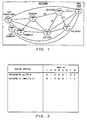
- FIGS. 1-10 show how various routing problems are solved in an exemplary 8 node network with the nodes located as follows: node 1, Chicago; node 2, Atlanta; node 3, San Francisco; node 4, Phoenix; node 5, Los Angeles; node 6, New York; node 7, Denver; node 8, Dallas. Trunk groups exist between the following pairs of nodes: 1,2; 1,6; 1,7; 1,8; 2,5; 2,6; 2,8; 3,4; 3,5; 3,6; 3,7; 3,8; 4,5; 4,7; 4,8; 5.6; 6,8; and 7,8. In this exemplary network, all the trunks are 2-way trunks.
- LL signifies lightly loaded
- HL signifies heavily loaded
- R signifies reserved status
- B signifies blocked (all trunks busy).
- LL lightly loaded
- H&LL heavily and lightly loaded
- R,H&LL reserved, heavily, and lightly loaded
- ITG - incoming trunk group OTG - outgoing trunk group
- S - far end switch ISW - intermediate switch
- R - routing AISW - accessible intermediate switch.
- the lightly loaded idle threshold is 5% for the Atlanta-Chicago trunk group, i.e., more than 5% of the trunks must be idle for the group to be marked as lightly loaded.
- this trunk group will be able to carry this traffic, and be used for calls between Chicago and other switches, as well as for calls between Atlanta and other switches. For example, if the switch in Dallas does not have any direct trunks to Chicago available, it could set up a call to Chicago over the 2-link route of Dallas to Atlanta to Chicago. See FIGS. 1 and 2.
- trunks used for those calls are idled. If new calls between Atlanta and Chicago arrive at a slower rate than the old calls disconnect, the number of idle trunks in the group eventually will exceed the 5% threshold. When this happens, the group is marked lightly loaded, and will be used again for new 2-link calls between Chicago and other switches, or between Atlanta and other switches.
- the group reaches the heavily loaded state, if new calls between Atlanta and Chicago arrive as fast or faster than the old calls disconnect, the number of idle trunks in the group will remain below the 5% threshold. In this state, the group is, in effect, dedicated for calls between Atlanta and Chicago only. Once the call load between these two switches exceeds the capacity of this group, Atlanta will begin looking for 2-link routes to Chicago, and vice versa.
- a switch needs to keep lists of the switches at the far end of available trunk groups; there is a LLITGS list, a LLOTGS list, a H&LLITGS list, a H&LLOTGS list, a RH&LLITGS list, and a RH&LLOTGS list.
- each switch in the network is assigned a unique Network Switch Number (NSN).
- NSN Network Switch Number
- FIG. 1 there are eight switches in a network, which have been assigned NSNs one through eight arbitrarily, corresponding to the node numbers previously discussed.
- the NSNs are used as the identity of the switches in the list of switches at the far end of available trunk groups, e.g., the LLITGS list.
- the Chicago switch has two lightly loaded incoming trunk groups; one from New York and one from Atlanta. Chicago's LLITGS list contains the NSNs of these two switches, i.e., NSN 6 and NSN 2 respectively.
- LLRISW Lightly Loaded Route Intermediate SWitch
- a bit map table is also a very compact way to store a far end switch list. For example, the list for each status level for a network with 256 switches only requires 32 bytes of data. This is a very important consideration since this list needs to be sent frequency in a common channel signaling message.
- RTNR finds all of the available 2-link routes through the network between the ASW and the DSW for a call. Some of these routes can be many miles long. If the two trunk groups that form such a long route are not equipped with echo cancelers, the route may not provide good transmission quality for voice calls. For instance, referring to FIG. 3, there are three available 2-link routes from Dallas to San Francisco; there are two relatively short routes via Phoenix and Denver respectively, and one very long route through New York. Even though the route through New York is available, it should not be used since it would not have acceptable transmission quality.
- the Dallas switch has a list of intermediate switches that it is allowed to use to set up calls to San Francisco.
- the Dallas switch also will have an Allowed Intermediate SWitch (AISW) list specified for every other switch in the network.
- AISW Allowed Intermediate SWitch
- Bit map tables can be used for AISW lists also.
- the Dallas switch can AND the LLRISW bit map table for San Francisco with its AISW bit map table for San Francisco to produce an Allowed, Lightly Loaded Route Intermediate SWitch (ALLRISW) bit map table list that only contains Phoenix and Denver. See FIGS. 3 and 4 for an illustration of this example.
- ALLRISW Lightly Loaded Route Intermediate SWitch
- any one of these routes can be used to set up the call. If a route is chosen from the list by some fixed algorithm, e.g., the first route to appear in the list is always used, then the 2-link traffic between two switches will always go over one particular route until that route becomes heavily loaded or busy. Once that occurs, all of this traffic then will be sent over the next route in the list.
- the ASW picks a random starting point in the bit map table, and starts a circular search through the table until an entry that is set is found. That entry identifies the NSN of the ISW to use for this call.
- One satisfactory choice of a random point is one position beyond the most recently used ISW for the route being searched.
- FIGS. 1 and 2 simply show Chicago's access pattern for lightly loaded groups (access to nodes 2 and 6, i.e., Atlanta and New York), and Chicago's lightly loaded and heavily loaded trunk group access pattern, i.e., nodes 2, 6, and 7 (to Atlanta, New York, and Denver).
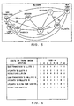
- FIGS. 3 and 4 show the routing of a call from Dallas to San Francisco when the direct route between those two nodes (nodes 8 and 3) is busy.
- San Francisco has a lightly loaded incoming trunk group switch access pattern showing availability to nodes 4, 5, 6, and 7 (Phoenix, Los Angeles, New York, and Denver).
- Dallas's lightly loaded outgoing trunk group switch access pattern shows access to nodes 1, 2, 4, 6, and 7 (Chicago, Atlanta, Phoenix, New York, and Denver).
- the intermediate switches that the Dallas node is allowed to use for routing calls to San Francisco only includes routes through nodes 4 and 7 since the transmission quality of a connection from Dallas to San Francisco via New York is likely to be unacceptable.
- the allowable routing ISW word has the bit positions for nodes 4 and 7 set to 1 so that the call from Dallas to San Francisco can be set up via either Phoenix or Denver.
- FIGS. 5 and 6 illustrate setting up a call from Atlanta to San Francisco under blockage states which permit the use of heavily loaded as well as lightly loaded trunks (see discussion with respect to FIG. 14.
- San Francisco's pattern of access via lightly loaded incoming trunk groups is to nodes 4, 6, and 7 (Phoenix, New York, and Denver).
- Atlanta's lightly loaded access to outgoing trunk groups is limited to nodes 1, 5, and 8 (Chicago, Los Angeles, and Dallas).
- Atlanta's allowed intermediate switches for a call to San Francisco is via nodes 5, 6, and 8 (Los Angeles, New York, and Dallas).
- San Francisco's access to lightly and heavily loaded incoming trunk groups is to nodes 4, 5, 6, and 7 (Phoenix, Los Angeles, New York, and Denver).
- Atlanta's access via lightly and heavily loaded outgoing trunk groups is to nodes 1, 5, 6, and 8 (Chicago, Los Angeles, New York, and Dallas).
- nodes 5, 6, and 8 Chos Angeles, New York, and Dallas
- it is found that a call from Atlanta to San Francisco can be set up via nodes 5 or 6, Los Angeles or New York. Note that in both of these routes, one of the trunk groups that must be used is heavily loaded.
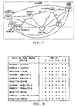
- FIGS. 7 and 8 illustrates a call from Phoenix to Chicago in which no routes are available using either lightly loaded or heavily loaded trunk groups but one route is available using the trunk group between Dallas and Chicago which is in the reserved status. Calls using facilities in the reserve status may be set up only if they are over the direct route from the ASW to the DSW or if no direct facilities connect the ASW to the DSW. In this particular case, there are no direct trunk groups between Phoenix and hicago (nodes 1 and 4) and it is assumed that the level of blockage is such that heavily loaded or reserved trunk groups may be used. In this particular case, the call from Phoenix to Chicago may be set up via Dallas using the Dallas to Chicago route which is in the reserved status.
- FIGS. 9 and 10 illustrate a call from Denver to Chicago, when the level of blockage over this route is sufficiently high so that heavily loaded trunk groups may be used.
- Denver and Chicago are connected via a busy trunk group so that the option of using a reserved facility, for example, going via Dallas and using the reserved facility between Dallas and Chicago, is not permitted.
- Chicago can access nodes 2 and 6 (Atlanta and New York) via lightly loaded and heavily loaded incoming trunk groups and Denver can access nodes 3, 4, and 8 (San Francisco, Phoenix, and Dallas) via lightly and heavily loaded trunk groups; as a result, no intermediate switching point is accessible by either a lightly loaded or heavily loaded trunk group from both Denver and Chicago, and the call is therefore blocked.
- a further check may be made to use a route having a combination of a lightly loaded and a heavily loaded trunk group in preference to a route having two heavily loaded trunk groups. This avoids the use of more heavily loaded trunk groups than is necessary.
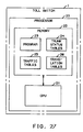
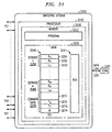
- FIG. 27 is a block diagram of the pertinent portions of a toll switch used for practicing this invention and showing connections to a common channel signaling network for communicating data messages among the toll switches of the network.
- Toll switch 1 comprises a processor 20 that includes a central processing unit 21 and a memory 22.
- the memory includes a program 23 for controlling the operations specified in the flow charts of the diagram trunk status tables 24 indicating the availability of individual trunks and the level of availability of trunk groups traffic tables 25 for keeping track of the level of blockage for different kinds of services between different switches and translation table 26 for translating the number of call setup requests to the identification of a destination switch.
- Processor 20 is also connected via link 28 to a common channel signaling network 27 which is interconnected to other toll switches and which is used for transmitting data messages including the trunk group availability data messages between the toll switches of the network.
- the ASW hunts for one of its available outgoing trunks to the ISW, and sets up the call on that trunk by sending an Initial Address Message (IAM) to the ISW.
- IAM Initial Address Message
- the ISW could either block the call, or it could send a CRANKBACK message to the ASW.
- the ASW Upon receipt of the CRANKBACK message, the ASW would select another ISW, if there is one, and attempt to set up the call through this newly selected ISW.
- the ASW can find a new ISW by continuing its circular search of the ALLRISW bit map table starting from the NSN of the switch which just cranked the call back.
- the ISW blocks the call due to a no circuit condition when it can not find an available outgoing trunk to the DSW.
- CRANKBACK is another option and can be used as an alternative to simply considering the call to be blocked at this point.
- RTNR check network status on a call-by-call basis, but it is also able to check and use any of the 2-link paths in the network. Because of this, RTNR provides a high degree of resiliency to network failures. RTNR will react automatically and immediately to troubles in the network, e.g., a switch outage or carrier failure, and route around the failure as much as possible. RTNR is also able to react automatically to unusual traffic patterns, e.g., those that occur on Mother's Day or following an earthquake in California.
- RTNR can be applied to 56 kilobit/second (KBPS) data calls, 64 KBPS data calls, broadband data calls, and calls for whatever other transmission capabilities are supported by the switch.
- KBPS kilobit/second
- 64 KBPS data calls 64 KBPS data calls
- broadband data calls a separate set of trunk groups, containing the circuits with this transmission capability, is specified in the switch.
- another set of lists of far end switches of these trunk groups which are available is maintained.
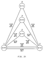
- FIG. 21 illustrates connections between switches which make it desirable to maintain these separate counts of available trunks for supporting different transmission types.
- Switches 11 and 12 are directly connected by two groups of facilities, one supporting voice-only and one supporting voice and data. When all of these trunks are idle, the number of available trunks in the voice trunk group is the sum of the number of trunks in both groups of facilities; the number of available trunks in the data trunk group is the number of trunks in the voice and data facilities group.
- switches 11 and 13 are connected by voice-only trunks which cannot even be used for transmitting data. Whereas switches 13 and 12 are connected by a single combined voice and data group. When a voice call is routed via switch 13, the capacity of the trunk group between switches 12 and 13 to support data is reduced.
- a switch in order for a switch to use RTNR for both voice and 56 KBPS data calls, a switch would have voice trunk groups and 56 KBPS data trunk groups to and from other switches in the network. The switch also would have a list of far end switches of lightly loaded incoming voice trunk groups, a list of far end switches of lightly loaded incoming 56 KBPS data trunk groups, etc.
- a switch When a switch wants to set up a 56 KBPS data call, it first checks for an idle circuit in the outgoing 56 KBPS data trunk group to the DSW; if one is found, the call will be set up on this direct data trunk to the DSW. If no direct 56 KBPS data trunk is available, the switch will ask the DSW to send a list of the far end switches of lightly loaded incoming 56 KBPS data trunk groups. With this information, the ASW will pick an ISW for this call, hunt an idle circuit in the outgoing 56 KBPS trunk group to the ISW, and set up the call on this trunk.
- trunks between two switches are split into dedicated trunk groups, i.e., some of the trunks are only used for voice calls, and the remaining trunks only carry 56 KBPS data calls.
- Separate networks under-utilize trunks. For example, a voice call will be blocked when all of the voice trunks are busy, even though one or more of the trunks dedicated for the 56 KBPS calls is available.
- trunks can be used for many types of calls, e.g., both voice and 56 KBPS data calls.
- a trunk When a trunk is used this way, it is considered a member of both the voice trunk group and the 56 KBPS data trunk group to the far end switch.
- the count of the available trunks in both the voice and 56 KBPS data trunk groups is decremented or incremented respectively.
- An integrated network is engineered to handle the combined forecasted call loads between two switches for many transmission types.
- An integrated network has the flexibility to handle a call overload between two switches for one transmission type if the traffic load between these two switches for the other transmission types are sufficiently under their engineered levels.
- An extreme call overload between two switches for one transmission type may cause calls between the two switches for all the transmission types to be blocked.
- the number of available trunks reserved is the difference between the minimum call load level desired between the two switches for this transmission type and the current completed call load between these two switches with this transmission type. Once this number of available trunks have been reserved, any additional available trunks can be used to complete calls requiring a different transmission capability.
- RTNR can meet different blocking objectives for different types of calls by controlling the use of direct and 2-link routes based on the load status of trunk groups and the blocked call measurements for each type of call on a per call basis.
- the performance of a multi-service network with integrated transmission capabilities can be optimized in terms of meeting the blocking objectives for all of the services and transmission types.
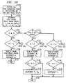
- FIGS. 11-20 are flow diagrams of actions performed in the ASW, ISW, and DSW in routing calls.
- DSW and switch are used interchangeably since the switch referred to therein is the DSW.
- FIGS. 11-15 are flow diagrams of actions performed in the ASW in response to receiving a call in order to route the call.
- a call is received in the ASW (action block 101).
- the ASW translates the incoming call directory number to find the DSW to which the call should be routed (action block 103).
- the transmission capability required for this call and the service type for the call is determined (action block 105).
- the counter for the number of call attempts to this DSW with this transmission type and this type of service is incremented (action block 107).
- test 109 is made to check whether there are any available trunks in the trunk group to the DSW for this transmission type. If so, then the next available trunk in this trunk group is found (action block 111 ).
- Test 121 determines whether the current number of calls completed to this DSW with this transmission and this service type is less than the minimum desired call load level to this DSW for this transmission and this service type. If so, the call is set up on this available direct trunk to the DSW (action block 141, FIG. 13), and the count of the number of completed calls to this DSW with this transmission and this service type is incremented (action block 143).
- the system checks if any reservation controls for this type of call need to be adjusted. If the upper bound for the number of trunks to reserve for calls to this DSW with this transmission and this service type is zero (test 145), then no reservation controls are in effect, and all of the actions the ASW needs to perform to route this call have been completed.
- Test 147 checks if the reservation control used to provide a minimum desired call load level for this type of call applies; if the just-incremented number of completed calls to this DSW with this transmission and this service type is still less than or equal to the minimum desired call load level for this type of call, then available trunks are being reserved for this type of call. If the difference between the minimum desired call load level for this type of call and the number of completions for this type of call is less than the upper bound for the number of trunks to reserve for this type of call (test 149), then the number of available trunks in this trunk group to be reserved for services not completing a minimum desired number of calls is decremented (action block 151 ). If the result of test 147 is negative or test 149 is positive, action block 151 is bypassed.
- test 153 checks if the reservation control used to keep available trunks from being used for 2-link connections until the completed call load for this type of call reaches the offered load level target for this type of call applies; if the just-incremented number of completed calls to this DSW with this transmission and this service type is still less than or equal to the offered call load level for this type of call, then available trunks are being reserved for this type of call. If the difference between the offered call load level for this type of call and the number of completions for this type of call is less than the upper bound for the number of trunks to reserve for this type of call (test 155), then the reserved state threshold for this trunk group is decremented (action block 157). If the result of test 153 is negative or test 155 is positive, then action block 157 is bypassed. All of the adjustments to the reservation controls have now been completed, and the ASW has now done all the actions needed to route this call.
- test 121 determines that the minimum desired number of calls to this DSW with this transmission and this service type have been completed, the system needs to check if this available trunk to the DSW is being reserved for another type of service that has not completed a minimum desired call load level to the DSW but is experiencing excessive blocking. This check must be done for each trunk group that this available trunk belongs to.
- the first transmission type supported to this DSW will be processed first (action block 123). If this available trunk is equipped to support this transmission type (test 125), then the system checks if the number of available trunks in the trunk group for this transmission type is less than the number of available trunks in this trunk group that are to be reserved for services unable to complete a minimum desired number of calls (test 127).
- test 129 determines if there are more transmission types supported to this DSW. If there are, the transmission type is set to the next type (action block 129), and the system proceeds to check if this available trunk is being reserved for a service defined for this transmission type (test 125). If there are no more transmission types supported to this DSW (test 129), then this available trunk can be used to complete this call (action block 141, FIG. 13).
- Test 133 is used to check if there is another available trunk in the direct trunk group. If so, then the sequence of actions starting with action block 111 (FIG. 11) is repeated. If not, or if the result of test 109 (FIG. 11), previously described for checking whether there were any available trunks in the direct trunk group, is negative, then the actions associated with trying to find an appropriate 2-link route to the DSW, described in FIG. 14, are performed.
- the first step of checking to find an available 2-link route is to send a status request message to the DSW (action block 161 ).
- the DSW performs the actions described infra with respect to FIG. 17.
- the DSW transmits a status response message which is received at the ASW (action block 163).
- optimum performance is obtained if several graded lightly loaded status values exist for each trunk group.
- the ASW searches the ISW(s) for the 2-link route having the lowest load status for the more heavily loaded link which lowest load status does not exceed the highest allowable load status.
- the selected route is one that has the lowest total load status sum when the load status of the two individual links is added.
- the ASW checks the total office blocking, the node-to-node blocking, and whether there is a direct trunk group to determine two parameters, L1 and L2, action block 165, with an illustrative set of parameters is shown in Table V. Computation of node-to-node blocking and total office blocking is described below in reference to FIG. 22.
- the maximum load status is set to reserved (action block 167). If not, test 169 is performed to check whether the current completed calls are less than the parameter L1 multiplied by the offered call load level. If so, then the maximum load status is set to heavily loaded (action block 171 ); if not, the max load status is set to lightly loaded (action block 173). Otherwise, the maximum load status is set to lightly loaded (action block 173). Action block 175 then searches the ISWs for the least loaded 2-link routes whose load does not exceed the max load status. Among the 2-link routes with the lowest load status, the one route that has the lowest total load status when summed over the 2 links on the route is selected. Test 181 (FIG. 15) checks whether such an ISW was found.
- test 181 finds that no ISW was found, this corresponds to failure to find a circuit for this call (action block 187) and the counter of blocked calls to the particular DSW for the particular kind of transmission and service is incremented (action block 189).
- action block 181 if a plurality of ISWs are found all corresponding to the same lowest max load status, and which also have the same lowest total load status when summed over the two links of the route, then the first ISW beyond a random starting point and searching over all ISWs in a circular fashion is selected.
- FIG. 16 describes the actions performed at the ISW.
- the incoming call is received (action block 201 ), the received directory number is translated to determine the DSW (action block 203), and the type of transmission for this call is determined (action block 205).
- the ASW could send the identification of the DSW as part of the IAM message.
- the identification of the DSW and the type of transmission provides the information needed to select the trunk group (action block 207) and test 209 is used to find if any trunks are available in that group. If so, then the next available trunk in that group is seized (action block 211) and the call to the DSW is set up over this trunk (action block 213). This ends the actions at the ISW (end, action block 215).
- the no circuit condition represents a state in which all trunks became unavailable between the time that the message from the DSW was sent to the ASW and the time that the call was forwarded from the ASW to the ISW. This type of situation should be quite rare and indicative of a very high load. As discussed in section 1.14, CRANKBACK is another option and can be used as an alternative to simply considering the call to be blocked at this point.
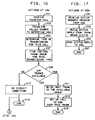
- FIG. 17 shows the actions performed at the DSW in response to receipt of a status request message.
- the DSW receives the status request message from the ASW (action block 231 ) and builds a status reply from the status of the trunk groups connected to the DSW (action block 233). This status is then sent to the ASW (action block 235) which ends (action block 237) the actions required to respond to a status request message.
- the DSW receives incoming calls and routes them to the destination connected to the DSW using methods well known in the art for completing calls to a destination. This destination may be a local or a tandem switching system or perhaps even a customer directly connected to the DSW.
- FIGS. 18-20 show additional actions for updating the trunk group load status as trunks are seized and released.
- FIG. 18 relates to trunk seizure.
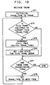
- FIG. 19 is a comparable flow chart for actions performed when a trunk is released.
- a counter or other indicator of different transmission types is initialized to transmission type 1 (action blocks 251 and 271 in FIGS. 18 and 19, respectively).
- a test is made (test 253 and 273 in FIGS. 18 and 19, respectively) of whether the seized or released trunk is equipped to support the transmission type being tested. If so, then the number of available trunks connected to the particular switch offering the particular transmission type is decremented (action block 257, FIG. 18) or incremented (action block 275, FIG. 19) depending on whether the trunk is seized or released, respectively.
- the load state for this trunk group is then updated as described hereinafter in FIG. 20 (action block 259).
- test 261 (FIG. 18) or test 277 (FIG. 19) is performed to check if there are more transmission types. If not, then the updating of the number of available trunks and load state for the appropriate trunk groups has been completed. If so, the transmission type is advanced to the next type (action block 263, FIG. 18) or action block 279, FIG. 19) and the actions beginning with tests 253 (FIG. 18) or 273 (FIG. 19), respectively, are repeated for this transmission type.
- FIG. 20 describes the actions required to update the load state for a trunk group.
- Test 281 checks whether the number of available trunks for the given connected switch and transmission type is now zero. If so, then the load state for that particular connected switch and transmission type is set to busy (action block 283). If not, then test 285 checks whether the available trunks for the particular connected switch and transmission type is equal to or less than the reserved state threshold for that connected switch and transmission type. If so, then the load state for that connected switch and transmission type is set to reserved (action block 287). If not, then test 289 is used to check whether the number of available trunks to the particular connected switch supporting the particular transmission type is equal to or less than the reserved state threshold associated with that group plus the heavily loaded state threshold associated with that group.
- action block 291 sets the load state to heavily loaded. If not, the load state is set to lightly loaded (action block 293). If there are a plurality of lightly loaded states, then action block 293 is expanded to include a group of tests to check the band of different lightly loaded states and to set the load state to the correct one of these bands.
- FIG. 26 describes the actions performed at the ASW when a call disconnects.
- the count of completed calls to the DSW for this type of transmission and service is decremented (action block 501).
- Test 503 checks whether reservation controls are in effect to this DSW with this type of transmission and service. This check is based on whether the upper bound of the number of trunks reservable for this type of call is greater than zero. If not, no further action is required. If the result of test 503 is positive, then test 505 checks whether the just decremented number of completed calls of this type is less than the minimum desired call load level for this type of call. If so, test 506 checks whether the difference between this minimum desired call load level and the completed number of calls is less than the reserved upper bound limit for this type of call.
- Action block 507 the number of available trunks to be reserved in the trunk group to the DSW for this transmission type for services which have not reached their minimum desired call load level is incremented (action block 507). Action block 507 is bypassed if the result of either test 505 or 506 is negative.
- test 511 if the number of completed calls to this DSW with this transmission and service type is less than the offered call load level for this type of call, test 512 is performed. Test 512 checks whether the difference between the offered call load level and completed call load level for this type of call is less than the reserved upper bound limit for this type of call. If so, the reserved state threshold for the trunk group to the DSW for this transmission type is incremented (action block 513). Action block 513 is bypassed if the result of either test 511 or 512 is negative.
- Simulations on the performance of the real-time network routing arrangement as contrasted with dynamic non-hierarchical routing show that the RTNR arrangement blocks less traffic under the same load.
- the blockage for RTNR using 6 states was under.5%. These six states include three graded lightly loaded states, heavily loaded, reserved and busy. Effectively, using three grades of lightly loaded status tends to spread traffic and reduces the number of routes which go into the heavily loaded status.
- the blockage using RTNR was significantly lower in all cases of low blockage and was lower for traffic that produced high blockage.
- the response of RTNR to facility failure was much more rapid in restoring the system to a state wherein the blockage was substantially reduced from the original blockage and showed low blockage throughout the recovery interval.
- the simulations showed that the traffic handling capacity of the 6 state RTNR appeared to be substantially better than that of an RTNR using a smaller number of states.
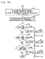
- FIGS. 22-24 show the actions that are performed on a periodic basis, e.g., once per minute, to monitor the performance of the integrated multi-service network, and accordingly adjust trunk group load state thresholds and reservation controls to optimize the throughput and performance of the network.
- Calls are classified by three parameters, the destination switch for the call, the transmission capability required for the call, e.g., voice, 64 KBPS data, etc., and the service type for the call, e.g., international call, domestic call, etc.
- the blocking rate for each set of calls which go to the same destination switch, require the same transmission capability, and have the same service type is checked. If the grade of service objective is not being met for a set of calls, trunk reservation controls are put into effect; these controls will increase the number of new attempts completed to this switch with this transmission and this service type, and thereby decrease the blocking rate for these new attempts.
- the first control is used when the minimum desired level of completed calls to this switch with this transmission and this service type is not being provided.
- This control reserves available trunks in the direct trunk group to this switch for this transmission capability so that these trunks can be used to complete new call attempts for this particular service type.
- This control reserves the number of available direct trunks needed to meet the minimum desired call load level for this service; the number of trunks reserved is the difference between this minimum desired call load level and the current number of completed calls to this switch for this service.
- This procedure controls when available trunks in this trunk group can be used again to complete calls to this switch for services which already have a minimum desired number of completed calls.
- the second control is used when the call load being offered to this switch with this transmission and service type is not being completed.
- This control reserves the number of available direct trunks needed to carry the call load being offered for this service; the number of trunks reserved is the difference between this offered call load level and the current number of completed calls to this switch for this service, with an appropriate upper limit, as specified for example in Table III.
- This procedure controls when available trunks in this trunk group can be used again in 2-link connections for calls to or from other switches.
- the number of trunks reserved in a trunk group by this control is the value used for the reserved state threshold for this trunk group.
- the program upon being entered at the end of the period, the program is set up to start checking calls to the first switch in the network (action block 401).
- Each of the transmission capabilities supported to this switch must be checked, so the first transmission type is processed first (action block 402).
- the reserved and heavily loaded state thresholds for the trunk group to this switch for this transmission type are initialized to zero, as is the number of available trunks in this trunk group to be reserved for services not completing a minimum desired number of calls (action block 403).
- each of the service types defined for this transmission type needs to be checked, so the first service type is processed first (action block 404).
- the number of attempts to the selected switch with this transmission and this service type during the period is multiplied by the blocking objective percentage for these calls (action block 405).
- the product is the number of these attempts which could have been blocked during the period while still meeting the blocking objective.
- the node-to-node blocking is determined as the ratio of the blocked calls for the destination switch with this transmission and service type divided by the attempts to the destination switch with this transmission and service type (action block 406).
- the total office blocking is determined as the ratio of the sum of the blocked calls for all the destination switches with the transmission and service type divided by the sum of attempts to all the destination switches with this transmission and service type.
- the average offered call load to be offered during the next period is approximated to be the sum of 60% of the average offered call load estimate for the last period plus 40% of the current completed call load to this switch with this transmission and this service type multiplied by a blocking correction factor equal to attempts divided by attempts minus the blocked calls (action block 407).
- Average offered call load is then multiplied by a variance factor to obtain the offered call load level target.
- a typical value of the variance factor is 1.1.
- trunks may need to be reserved for this service during the upcoming period.
- the number of trunks to be reserved should be limited to an upper bound, because once a substantial number of available trunks have been reserved, reserving additional trunks as they become available does not improve the performance of the reservation controls.
- An upper bound for the number of trunks reserved for this service is set, chosen from the smaller of 5% of the number of calls to be offered to this switch with this transmission and this service type limited to a range of two to ten (action block 419).
- the reserved state threshold for this trunk group is raised to account for the number of available trunks in this trunk group to be reserved for direct calls to this switch for this service (action block 427).
- the heavily loaded state threshold to be used for this trunk group during the next period must be adjusted to reflect the offered call load for this service using this trunk group; the heavily loaded state threshold for this trunk group is raised by the smaller of 5% of the offered call load level for this service limited to a range of two to ten (action block 431, FIG. 24).
- the counters used to accumulate the number of call attempts and blocked calls to this switch with this transmission and this service type during the next period are set to zero (action block 433).
- test 435 If there are more service types for this transmission type (test 435), then the service is set to the next type (action block 437) and the system proceeds to check the blocking rate for calls to the same switch using the same transmission type, but for this new service type (action block 405, FIG. 22).
- action block 435 If there are no more service types for this transmission type (action block 435), then the system checks if there are more transmission types supported by the network to this switch (action block 439). If there are more transmission ryes then the system sets the transmission to the next type (action block 441) and proceeds to check the blocking rate for calls to the same switch for all of the services for this new transmission type (action block 403, FIG. 22).
- the system checks if there are any more switches in the network (test 443). If there are, the system is set up to check the next switch (action block 445), and proceeds to check all of the transmission types and service types for this switch (action block 402, FIG. 22). If all the switches have been checked, the periodic check for blocking and adjustment of load state thresholds is completed.
- This section describes an alternative arrangement for using status request and status response messages. It addresses the problem in the arrangement described hereintofor, a delay for sending a status request message and waiting for the response is incurred every time no direct route is available.
- the basic arrangement for avoiding this delay is to use the most recently received status response from the destination switch and to make sure that this status response is updated by requesting a new status response.
- the new status response is then stored for use the next time that a status response from that DSW destination switch is needed. Since the status of the destination switch will sometimes not be up to date, it is necessary to provide for a CRANKBACK procedure since the route picked based on the not up-to-date destination switch status has a greater probability of being, in fact, blocked.
- FIG. 25 is normally entered after test 109 (FIG. 11) has determined that there are no available direct trunks.
- a status request message is sent to the destination switch (action block 301) and when the response is received from the destination switch, this response is stored for future use (action block 305).
- the stored previous status response from that destination switch is used (action block 303) and the actions previously described with respect to FIG. 14 starting with test 165 are performed. These actions are used to find the appropriate intermediate switch to be used for routing this call.
- action block 217 In case no circuit is available at the intermediate switch, the no circuit condition of action block 217 of FIG. 16, which in the FIG. 16 flow chart led to an end of attempts to route this call. If the alternative approach of FIG. 25 is used, it is recognized that it is necessary to use up-to-date destination switch status information. In that case, action block 217 (FIG. 16) is followed by action block 311 (FIG. 25) which, for the sake of clarity, shows the no circuit condition at the intermediate switch.
- the intermediate switch sends a CRANKBACK message to the accessing switch (action block 313) which is received at the access switch in action block 315.
- the access switch waits for the status response from the destination switch (action block 317).
- This response may already have been received or may not yet have been received since the CRANKBACK message and the status response message are each received after one message round trip time, from the time that the access switch started looking for a route for the call in question.
- the status response message from the DSW is received, then that status response is stored and is used for the subsequent search for a route starting with action block 165 of FIG. 14.
- trunk group status information can then be broadcast to all switches.
- the arrangement may be advantageous if good message broadcast facilities are available in the data network interconnecting the switches. With this arrangement, all switches periodically broadcast their trunk group status to all other switches, and as request messages are required. The most recently received trunk group status data replaces any older version and is directly used by the ASW.
- a CRANKBACK procedure, described supra, is advisable since the status information is not quite as current as it is if requested by the ASW in response to a call setup request.
- Code group controls are used when the traffic load to a called number, or a set of numbers, is not being completed at or near the expected rate either because of unusual peaks or equipment failure. Code group controls are used to cut back attempts to the affected codes so that network resources are not excessively tied up for calls that have a poor probability of completing. These controls are independent of network routing strategies, and are unchanged by the use of RTNR.
- the ASW filters out at least some of the requests for connections to the affected code groups and does not even try to route these calls; unaltered requests are routed in the normal fashion.
- Expansive routing controls are used to increase the number of alternate routes from an ASW to a DSW by specifying additional alternate routes to those already contained in an engineered routing list.
- Network managers determine which potential routes in the network are carrying less than their engineered loads, and therefore can be used as alternate routes to handle some traffic peak.
- RTNR does not use engineered routing lists; in fact, RTNR automatically checks every possible route through the network for each call, and uses the lightest loaded route available. As such, expansive routing controls have been integrated into call routing.
- Restrictive routing controls can be used, if necessary, to handle general traffic loads which are focused on a particular switch, i.e., the load is not focused on a code groups or a limited set of code groups.
- Restrictive routing controls also are intended to cut back the number of attempts directed to this switch, so that network resources are not excessively tied up completing calls to this switch, and thereby spread congestion to other switches in the network.
- RTNR gives network managers a readily usable framework for the specification of restrictive routing controls. Alternate routing can be restricted on the basis of the load status of the routes. For a moderate overload, only alternate routes that are very lightly loaded, or lightly loaded can be used. For a more extreme call overload, only very lightly loaded routes can be used. Again, these actions are more closely integrated with call routing.
- Network managers specify an override routing pattern to use for attempts to the switch under overload, and routing is automatically adjusted to this override pattern. However, it may not be necessary to provide restrictive routing controls; field experience and further simulations are necessary to check more definitely to see whether restrictive routing controls will still be required in a particular network.
- the ASW selects the route
- the DSW it is also possible for the DSW to receive ASW trunk group status and to select the route based on that data and the DSW's own status data.
- While this embodiment relates to circuit connections, the principles of this invention can also be applied to packetized data connections.
- the same method for selecting a route can be used in order to load traffic onto the more lightly loaded trunk groups or data circuits.
- the following remaining portion of the detailed description relates to arrangement for reserving trunks in a first choice group for particular types of traffic.
- key traffic types special attempts are made to offer service up to the load objective.
- Traf (k + 1) , . . . , traf n are standard traffic types which are not so protected.
- a i is the actual load being carried for the traffic type traf i .
- O i is the load objective for traf i .
- L i is the reserve limit for traf i .
- R i is the number of trunks reserved in the group for additional service for traf i .
- R i is a minimum of 0 as indicated by one of the terms of the max expression, and, if not 0, then the minimum of the two terms L i and (O i - A i ). In other words, R i is a non-negative number which represents a positive difference between O i and A i up to a limit L i .
- T K is the key reserve sum and is the sum of the R i 's for the first k services.
- T T is the total reserve sum and it is the sums of the R i 's of all n types of service.
- the following algorithms are used to decide whether a trunk may be seized in a group. For first choice routes for key services (i ⁇ k) and A i is less that O i , seize a trunk if M (the number of available trunks in the group) is greater than 0. In other words, if the actual load being carried for a key service is less than the objective load, seize any available trunk in the first choice route. Next, if i > k, i.e., (if this is a standard service) and A i is less than O i (the actual load is less than the objective load), seize a trunk if M > T K i.e., if the number of available trunks is more than the key reserve sum).
- Table VI is an example to illustrate the principles of this invention.
- Services 1 and 2 are key services and services 3 and 4 are standard services.
- the load objectives for each of the four services are 10, 5, 20, and 30, respectively.
- the reserve limit for each of these services are 6, 5, 10, and 10, respectively. Note, for example, that for service 4 which has a load objective 30, the reserve limit is 10; the reserve limit is a number designed to handle surges of traffic and in engineering this system, it was felt that to be prepared to handle a surge of 10 even for this standard service with load objective of 30 should give adequate protection to that service.
- the actual load in the system is 9 units for service 1, 5 units for service 2, 18 units for service 3, and 15 units for service 4.
- the number of trunks reserved for additional service for each of these four services is then 1, 0, and 2 for the first three services, in this case representing a positive or zero difference between the objective and the actual load being carried, and is 10 for service 4, since this number is limited to the reserve limit for that service.
- T K the key reserve sum is 1 representing the sum of the reserves for services 1 and 2
- T T the total reserve sum is 13, the sum of the reserve quantities for all of the services.
- M the total number of available trunks, is 0, then no trunks are available regardless of which type of service is being sought.
- L i is a function of node to node blockage as described with respect to Table III. Using this approach, L i is increased for a trunk group having high blockage, and can be 0 for low blockage. In networks where extensive alternate routing is available, it is advantageous to use arrangements wherein L i is calculated as discussed with respect to Table III; where alternate routes are less extensive, the approach described above with respect to Table VI is preferable.
- FIG. 28 illustrates the process of this invention.
- a call for connection via an outgoing or two-way trunk group is received (action block 3100) at switching system 3200.
- the first choice trunk group for this call is determined as is i, the type of service for this call within this trunk group.
- the parameters for that type of service namely A i , the actual present load, O i , the objective load for that service, L i , the reserve limit for that service are determined, as are the parameters of the trunk group, namely, M, the number of available trunks, T T the total reserve parameter, and T K the key services reserve parameter (action block 3102).
- the actual load is compared with the objective load for that service (test 3104).
- test 3106 is used to determine whether the number of idle trunks M exceeds the total reserve T T . If not, then test 3160, to be described below, is used to check if there are additional alternate trunk groups. If the number of available trunks M exceeds the total reserve parameter T T , then a trunk is seized from the trunk group, the number of idle trunks M is decremented and the load for the particular service A i is incremented (action block 3108). This ends the process of selecting a trunk for carrying the call (action block 3110).
- test 3120 is used to determine whether this is a key service. If this is a key service, test 3122 simply checks whether there are any available trunks, i.e., whether M is greater than 0. If so, then a trunk is seized, M is decremented, and A i the load for that kind of service is incremented (action block 3124). Next, test 3126 checks whether the difference between the objective load and the updated actual load is less than the reserve limit L i . If so, then both the total reserve T T and key reserve T K are decremented (action block 3128) and the process of selecting a trunk for the incoming call is completed (end block 3130).
- the T T and T K parameters are periodically audited to make sure that they agree with the sum of all positive differences between objective and actual loads for the key and for all services, respectively, each term of that sum being subject to the reserve limit parameter for that term (see equations (4), (5), and (6).
- test 3140 determines whether the number of available trunks exceeds the key reserve parameter. If not, then no trunks are to be seized from this trunk group and an alternate trunk group is to be examined starting with test 3160 to be described below. If the number of available trunks exceeds the reserve parameter for key services, then a trunk is seized from the group, M, the number of available trunks, is decremented, and A i , the actual load for the service is incremented (action block 3142). In test 3144 a check is made whether the difference between the objective load and the actual load as updated is less than the reserve limit for this kind of service.
- T T is decremented (action block 3146) and the process of selecting a trunk for the incoming call has been completed (end block 3130). If the difference between the objective and the actual load is still greater than or equal to the reserve limit, then T T is not decremented.
- Test 3160 (FIG. 29), which is entered initially because no trunks are available for the incoming call in the first choice trunk group, checks whether there are additional alternate trunk groups for the destination of the incoming call. If not, then the NO CIRCUITS AVAILABLE condition is recognized (action block 3162) and the call cannot be completed. Under these circumstances, the calling customer on the incoming call is normally given overflow tone or some type of ALL CIRCUITS BUSY announcement. If the result of test 3160 is positive that there are additional alternate trunk groups available, then action block 3164 finds the next alternate trunk group and determines the number of available trunks M and the total reserve parameter T T for that trunk group.
- test 3166 If M exceeds T T (test 3166), then a trunk is seized from that group, M the number of available trunks for that group is decremented and A i is incremented (action block 3168). Note that the reserve parameters are not changed when a trunk from an alternate group is used. This completes the process of seizing a trunk for handling the incoming call (end block 3170). If the result of test 3166 indicates that the available number of trunks is less than or equal to the total reserve parameter T T , then test 3160 is re-entered to search for an additional alternate trunk group.
- FIG. 30 is a flow chart of the actions performed in response to an incoming call on a two-way trunk group.
- Incoming calls for the two-way trunk group also have objective loads and actual loads for different kinds of services and have a reserve limit.
- a test is made whether the objective load is equal to or greater than the actual load for incoming calls for this kind of service (test 3302). If not, A i is incremented (action block 3305) but no actions are required to update the reserve limits T T and T K and the actions with respect to these reserve limits are completed (end block 3310).
- test 3304 is used to determine if this is a key service. If so, then test 3306 is used to determine whether the objective load minus the actual load is less than the reserve limit for that service. If so, then the two reserve parameters T T and T K are both decremented. If not, neither of the total reserve parameters are decremented. This completes the actions of updating the total reserve parameters for this call under these circumstances (end block 3310). If the result of test 3304 indicates that this is not a key service, then test 3320 is used to determine whether the difference between the objective load and the actual load for this service is less than the reserve limit for this service. If so, then the total reserve parameter is decremented (action block 3322). If the total reserve parameter is not decremented, this completes the actions for modifying the reserve parameters in response to the receipt of the incoming call on the two-way trunk group (end block 3310).
- FIG. 31 is a block diagram of a switching system for implementing this invention.
- the switching system has a plurality of outgoing or two-way trunk groups, TG1,..., TGX connected as well as one or more groups of incoming trunks such as trunk group TGY.
- the process described in FIGS. 28 and 29 is used only with respect to the outgoing or two-way trunk groups.
- Switching system 3200 is controlled by processor means 3210 comprising memory 3220 that includes a program 3222 for executing the steps of the process of FIGS. 28 and 29 and data 3230 for storing data for each of the trunk groups such as block 3240 for trunk group 1 and block 3241 for trunk group X.
- Block 3240 comprises a plurality of n blocks such as block 3250 for storing parameters associated with the first service and block 3260 associated for storing blocks associated with the nth service.
- Block 3250 comprises storage for A 1 the actual load for service type 1, O 1 the objective load for service 1 and L 1 the reserve limit for the first service.
- block 3240 contains common area 3270 which includes the identifications and availability of the trunks in the trunk group 3272, the key services parameter T K , 3273 the total reserve parameter, T T , and M the number of available trunks stored in block 3274.
- FIG. 30 also shows a control terminal 3280 for an administrator to transmit requests for changes to the stored parameters, such as O and L for a particular trunk group, over data link 3281.
- the terminal can be for a common carrier network administrator for common carrier trunk groups, or from a customer network administrator for a trunk group connecting switching system 3200 to the customer's PBX.
- the requested changes are examined by the processor 3210 and inserted in the data block 3240,...,3241 for the approximate trunk group.
- the data link can be a D-channel of the ISDN connection.
- the data link need not be a data link dedicated for this purpose but can be a virtual data channel over a facility for transmitting data or data and voice.
- the number of trunks in the trunk group is not tied to the sums of the objective loads.
- the sums of the load objectives for the different services can exceed the number of available trunks.
- the arrangements described protect the load objectives of the key services, which might include emergency services or services that are especially profitable for the operators of the telecommunications network. Further, there is protection against the effects of excessive surges in one kind of service because of the two reserve parameters.
- reserves are only used for first choice routes (which can include indirect as well as direct routes), in other embodiments, the reserve concept can also be used for alternate routes.
Claims (16)
- Procédé de sélection d'un circuit de télécommunications disponible pour un service pour un appel vers une destination dans un système fournissant une pluralité de services, comprenant les étapes de:si la charge réelle dudit service vers ladite destination sur un premier groupe de circuits sélectionnables est inférieure à une cible prédéterminée, sélection d'un circuit disponible dudit premier groupe de circuits sélectionnables (3102, 3104, 3142); etsi la charge dudit service vers ladite destination sur ledit premier groupe de circuits sélectionnables est égale ou supérieure à ladite cible prédéterminée, sélection d'un circuit disponible dudit premier groupe sélectionnable seulement si le nombre de circuits disponibles dépasse une somme de réserve (3106, 3108);dans lequel ladite somme de réserve est la somme des circuits réservés pour tous les services dont la charge réelle est inférieure à la charge cible de ce service pour ledit premier groupe de circuits sélectionnables.
- Procédé de la revendication 1, dans lequel au moins un de ladite pluralité de services est un service clé devant recevoir un traitement préférentiel et dans lequel ladite étape de sélection si la charge est inférieure à ladite cible prédéterminée comprend:si ledit service est un service clé, la sélection d'un circuit disponible dudit premier groupe de circuits sélectionnables (3120, 3122, 3124); etsi ledit service n'est pas un service clé, la sélection d'un circuit disponible dudit premier groupe de circuits sélectionnables uniquement si le nombre de circuits disponibles dudit groupe dépasse une somme de réserve (3120, 3140, 3142).
- Procédé de la revendication 2, dans lequel ladite somme de réserve clé est la somme de circuits réservés pour ledit groupe pour tous les services clés dont la charge réelle est inférieure à leur charge cible prédéterminée.
- Procédé de la revendication 1, dans lequel le nombre de circuits réservés pour un service pour ledit premier groupe de circuits sélectionnables est fonction de toute différence positive entre la charge cible et la charge réelle pour ce service assuré sur ledit premier groupe de circuits sélectionnables.
- Procédé de la revendication 4, dans lequel ladite fonction de la différence est une valeur réelle de la différence.
- Procédé de la revendication 4, dans lequel ladite fonction est limitée à une limite de réserve préspécifiée.
- Procédé de la revendication 4, dans lequel une sélection d'un circuit d'un premier groupe de circuits sélectionnables quand la charge réelle pour ledit service est inférieure à la cible de charge modifie ladite somme de réserve totale à moins que la différence entre la charge cible et la charge réelle pour ledit service sur ledit premier groupe sélectionnable soit supérieure à une limite de réserve pour ce service sur ce groupe.
- Procédé de la revendication 1, comprenant en outre l'étape de:
si la charge réelle pour ledit service est égale ou supérieure à ladite cible pour ladite charge pour ledit premier groupe sélectionnable et le nombre de circuits disponibles dudit premier groupe sélectionnable est égal ou inférieur à ladite somme de réserve totale, sélection d'un circuit d'un autre groupe. - Procédé de la revendication 8, dans lequel ladite étape de sélection d'un circuit d'un autre groupe comprend l'étape de:
sélection d'un circuit d'un autre groupe si le nombre de circuits disponibles dans ledit autre groupe est supérieur à une somme de réserve totale pour ledit autre groupe. - Procédé de la revendication 9, comprenant l'étape de:
si un circuit est sélectionné dans un autre groupe, maintien de la présente valeur de la somme de réserve totale pour ledit autre groupe. - Procédé de la revendication 1, dans lequel ledit premier groupe de circuits sélectionnables est connecté à un commutateur qui n'est pas directement connecté à une première et une deuxième destination desservies par ledit premier groupe de circuits sélectionnables comme premier groupe sélectionnable et les appels pour un type de service vers ladite première et ladite deuxième destination sont traités comme des appels pour un différent type de service, chacun avec sa propre cible prédéterminée.
- Procédé de la revendication 1, dans lequel ledit premier groupe de circuits sélectionnables est connecté à un commutateur qui est directement connecté à une première destination et non directement connecté à une deuxième destination, les deux destinations étant desservies par ledit premier groupe de circuits sélectionnables comme premier groupe sélectionnable, dans lequel les appels pour un type de service vers ladite première et ladite deuxième destination sont traités comme des appels pour un différent type de service, chaque type avec sa propre cible prédéterminée.
- Procédé de la revendication 1, dans lequel ledit premier groupe de circuits sélectionnables achemine un trafic bidirectionnel et dans lequel une cible prédéterminée séparée est maintenue pour un type de service pour le trafic entrant et sortant pour un type particulier de service.
- Dispositif dans un premier système de commutation de télécommunications (1) pour desservir une pluralité de types de services différents d'appels, le dispositif pour déterminer un groupe à travers un réseau de télécommunications pour desservir un appel ayant un type de service donné, comprenant:un moyen de commande (20), comprenant une mémoire (22) pour une pluralité de tables (24, 25, 26) et un programme (23), sensible à des données mémorisées dans ladite pluralité de tables;en réponse à un appel entrant (3100) vers ledit premier système et à des données mémorisées dans une table de traduction dudit moyen de commande, ledit moyen de commande fonctionnant sous la commande d'une première partie dudit programme pour déterminer que ledit appel devrait être acheminé vers une destination;ledit moyen de commande fonctionnant sous la commande d'une deuxième partie dudit programme pour déterminer à partir desdites données un premier groupe de circuits sélectionnables pour accéder à ladite destination (3102);ledit moyen de commande fonctionnant sous la commande d'une troisième parie dudit programme pour déterminer si la charge réelle pour ledit service vers ladite destination est inférieure à une cible prédéterminée, mémorisée dans lesdites données, pour ledit type de service et ladite destination (3104);si ladite charge réelle est inférieure à ladite cible, ledit moyen de commande fonctionnant sous la commande d'une quatrième partie dudit programme pour sélectionner un circuit disponible dudit premier groupe sélectionnable, et si ladite charge réelle est égale ou supérieure à ladite cible, pour sélectionner un circuit disponible dudit premier groupe sélectionnable seulement si le nombre de circuits disponibles dépasse une somme de réserve;dans lequel ladite somme de réserve est la somme de circuits de réserve pour tous les services dont la charge réelle est inférieure à la charge cible pour ce service pour ledit premier groupe de circuits sélectionnables.
- Dispositif de la revendication 14, dans lequel ladite pluralité de types de services différents comprend au moins un type de service clé et dans lequel ledit moyen de commande fonctionnant sous la commande de ladite quatrième partie pour sélectionner si ladite charge réelle est inférieure à ladite cible sélectionne tout circuit disponible dudit premier groupe sélectionnable si ledit type de service est un type de service clé et sélectionne un circuit disponible dudit premier groupe sélectionnable seulement si le nombre de circuits disponibles dudit groupe dépasse une somme de réserve clé variant dynamiquement si ledit type de service n'est pas un service clé.
- Procédé de la revendication 15, dans lequel ladite somme de réserve clé est la somme de circuits réservés pour ledit groupe pour tous les services clés dont la charge réelle est inférieure à leur charge cible prédéterminée.
Applications Claiming Priority (2)
| Application Number | Priority Date | Filing Date | Title |
|---|---|---|---|
| US07/501,334 US5101451A (en) | 1988-12-29 | 1990-03-26 | Real-time network routing |
| US501334 | 1995-07-12 |
Publications (3)
| Publication Number | Publication Date |
|---|---|
| EP0449480A2 EP0449480A2 (fr) | 1991-10-02 |
| EP0449480A3 EP0449480A3 (en) | 1992-07-29 |
| EP0449480B1 true EP0449480B1 (fr) | 1997-01-29 |
Family
ID=23993114
Family Applications (1)
| Application Number | Title | Priority Date | Filing Date |
|---|---|---|---|
| EP91302321A Expired - Lifetime EP0449480B1 (fr) | 1990-03-26 | 1991-03-18 | Routage en temps réel dans un réseau |
Country Status (6)
| Country | Link |
|---|---|
| US (1) | US5101451A (fr) |
| EP (1) | EP0449480B1 (fr) |
| JP (1) | JP2849227B2 (fr) |
| CA (1) | CA2036769C (fr) |
| DE (1) | DE69124404T2 (fr) |
| ES (1) | ES2096622T3 (fr) |
Families Citing this family (97)
| Publication number | Priority date | Publication date | Assignee | Title |
|---|---|---|---|---|
| JP2875598B2 (ja) * | 1990-06-27 | 1999-03-31 | 富士通株式会社 | ノードにおけるネットワーク経路設定方式 |
| US5513323A (en) * | 1991-06-14 | 1996-04-30 | International Business Machines Corporation | Method and apparatus for multistage document format transformation in a data processing system |
| US5392344A (en) * | 1991-10-03 | 1995-02-21 | At&T Corp. | Communications network class-of-service routing |
| US5537468A (en) * | 1991-10-15 | 1996-07-16 | Siemens Aktiengesellschaft | Method for the non-hierarchical routing of traffic in a communications network |
| WO1993009629A1 (fr) * | 1991-11-04 | 1993-05-13 | Motorola, Inc. | Procede et appareil servant a reserver une voie de communication dans un systeme de communication a telepoints |
| US5583928A (en) * | 1992-06-19 | 1996-12-10 | British Telecommunications Public Limited Company | Detecting local exchange failure and resultant control of a communications network |
| FR2702859A1 (fr) * | 1993-03-17 | 1994-09-23 | Philips Electronique Lab | Dispositif de recherche d'un plus court chemin dans un réseau. |
| US6738357B1 (en) * | 1993-06-09 | 2004-05-18 | Btg International Inc. | Method and apparatus for multiple media digital communication system |
| US5444773A (en) * | 1993-06-30 | 1995-08-22 | Harris Corporation | Method for releasing unnecessary trucks from a telephone call |
| JP3260011B2 (ja) * | 1993-07-13 | 2002-02-25 | 松下電器産業株式会社 | 移動体通信システムの通話路管理方法および移動体通信システム |
| US5590176A (en) * | 1993-08-30 | 1996-12-31 | Lucent Technologies Inc. | Arrangement for local trunk hunting in a distributed switching system |
| US5519836A (en) * | 1994-03-25 | 1996-05-21 | At&T Corp. | Method of on-line permanent virtual circuit routing |
| US5694546A (en) | 1994-05-31 | 1997-12-02 | Reisman; Richard R. | System for automatic unattended electronic information transport between a server and a client by a vendor provided transport software with a manifest list |
| DE4422546A1 (de) * | 1994-06-28 | 1996-01-04 | Alcatel Sel Rft Gmbh | Verfahren zur Bestimmung von Leitweglisten in einem Nachrichtennetz für vermittelte Verbindungen und Rechner und Datenträger dafür |
| ATE188793T1 (de) * | 1994-10-12 | 2000-01-15 | Touchtunes Music Corp | Intelligentes system zur numerischen audio- visuellen reproduktion |
| CA2162200A1 (fr) * | 1994-11-23 | 1996-05-24 | Gagan Lal Choudhury | Methode efficace pour offrir plusieurs qualites de service avec protection contre les surcharges dans l'utilisation de ressources mises en commun |
| US5550911A (en) * | 1994-11-29 | 1996-08-27 | Lucent Technologies Inc. | Adjunct call handling for accessing adjunct-based capabilities platform |
| US5787160A (en) * | 1994-12-08 | 1998-07-28 | Mci Communications Corporation | Intelligent routing of special service calls |
| WO1996021989A1 (fr) | 1995-01-09 | 1996-07-18 | Mci Communications Corporation | Traitement ameliore des appels de surcharge |
| US5539815A (en) * | 1995-02-24 | 1996-07-23 | At&T Corp. | Network call routing controlled by a management node |
| US5973724A (en) * | 1995-02-24 | 1999-10-26 | Apple Computer, Inc. | Merging multiple teleconferences |
| US5572582A (en) * | 1995-02-24 | 1996-11-05 | Apple Computer, Inc. | Method and apparatus for establishing communication between two teleconferencing endpoints |
| US5854898A (en) * | 1995-02-24 | 1998-12-29 | Apple Computer, Inc. | System for automatically adding additional data stream to existing media connection between two end points upon exchange of notifying and confirmation messages therebetween |
| US5793842A (en) * | 1995-02-27 | 1998-08-11 | Schloemer; Jerry R. | System and method of call routing and connection in a mobile (remote) radio telephone system |
| US5615254A (en) * | 1995-04-04 | 1997-03-25 | U S West Technologies, Inc. | Methods and systems for dynamic routing in a switched comunication network |
| US5828746A (en) * | 1995-06-07 | 1998-10-27 | Lucent Technologies Inc. | Telecommunications network |
| US5583929A (en) * | 1995-06-07 | 1996-12-10 | Lucent Technologies Inc. | Customer oriented telecommunications network |
| US5644632A (en) * | 1995-06-07 | 1997-07-01 | Lucent Technologies Inc. | Distributed key telephone station network |
| US5608790A (en) * | 1995-06-07 | 1997-03-04 | Lucent Technologies Inc. | Trunk utilization in a telecommunications network |
| SE504712C2 (sv) * | 1995-07-04 | 1997-04-07 | Ericsson Telefon Ab L M | Förfarande och anordning för att dirigera trafik i ett kretskopplat nät |
| DE19534755C1 (de) * | 1995-09-19 | 1997-01-30 | Siemens Ag | Verfahren zum Vermitteln von Schmalband-Leitungsbündeln zwischen Kommunikationssystemen über ein ATM-Kommunikationsnetz |
| US5881140A (en) * | 1996-01-16 | 1999-03-09 | Dsc Telecom L.P. | Apparatus and method of determining switch utilization within a telecommunications network |
| DE19619996A1 (de) * | 1996-05-17 | 1997-11-20 | Deutsche Telekom Ag | Verfahren zur richtungsabhängigen Belegungsverteilung bei wechselseitig betriebenen Leitungsbündeln |
| US5751706A (en) * | 1996-06-05 | 1998-05-12 | Cignal Global Communications, Inc. | System and method for establishing a call telecommunications path |
| EP0941619A1 (fr) | 1996-11-22 | 1999-09-15 | Siemens Aktiengesellschaft | Procede et systeme d'organisation dynamique du trafic dans un reseau de communication |
| CA2192122A1 (fr) | 1996-12-05 | 1998-06-05 | Gerald Richard Ash | Acheminement force des appels entre commutateurs |
| CA2218263C (fr) * | 1996-12-23 | 2001-10-09 | Lucent Technologies Inc. | Architecture d'un systeme de telecommunications |
| US5999614A (en) * | 1996-12-23 | 1999-12-07 | Lucent Technologies Inc. | Telecommunications system architecture |
| US5995612A (en) * | 1996-12-23 | 1999-11-30 | Lucent Technologies Inc. | Telecommunications system architecture |
| US5901208A (en) * | 1996-12-23 | 1999-05-04 | Mci Worldcom, Inc. | Method and system for combing modular availability projections in a telecommunication system |
| US6021191A (en) * | 1997-03-05 | 2000-02-01 | At&T Corp. | Automatic routing technique |
| US5956396A (en) * | 1997-05-06 | 1999-09-21 | At&T Corp | Class-of-service automatic routing |
| US6151315A (en) * | 1997-06-02 | 2000-11-21 | At&T Corp | Method and apparatus for achieving fabric independent routing technique |
| US6009329A (en) * | 1997-07-15 | 1999-12-28 | Lucent Technologies, Inc. | System and method for hunting trunk lines with a GSM wireless base station and GSM wireless infrastructure employing the same |
| FR2769165B1 (fr) | 1997-09-26 | 2002-11-29 | Technical Maintenance Corp | Systeme sans fil a transmission numerique pour haut-parleurs |
| US6169892B1 (en) * | 1997-11-22 | 2001-01-02 | Northern Telecom Limited | Flow control of authentication triplet request for reducing usage time of a central processor |
| JPH11191811A (ja) * | 1997-12-25 | 1999-07-13 | Fujitsu Ltd | 共通線信号装置及びその制御方法 |
| US6134530A (en) * | 1998-04-17 | 2000-10-17 | Andersen Consulting Llp | Rule based routing system and method for a virtual sales and service center |
| US7194078B2 (en) * | 1998-05-28 | 2007-03-20 | Siemens Communications, Inc. | Network redirection control routing |
| FR2781580B1 (fr) | 1998-07-22 | 2000-09-22 | Technical Maintenance Corp | Circuit de commande de son pour systeme de reproduction audiovisuelle numerique intelligent |
| FR2781591B1 (fr) | 1998-07-22 | 2000-09-22 | Technical Maintenance Corp | Systeme de reproduction audiovisuelle |
| CA2278092A1 (fr) * | 1998-08-12 | 2000-02-12 | Craig L. Decaluwe | Methode et appareil pour eloigner d'un commutateur en panne l'acheminement du trafic des donnees dans un reseau de communication |
| US6459899B1 (en) | 1998-09-14 | 2002-10-01 | Jerry R. Schloemer | Cellular radio routing system |
| US7502315B2 (en) * | 1998-12-21 | 2009-03-10 | At&T Intellectual Property Ii, L.P. | Method for hybrid network planning |
| FR2796482B1 (fr) | 1999-07-16 | 2002-09-06 | Touchtunes Music Corp | Systeme de gestion a distance d'au moins un dispositif de reproduction d'informations audiovisuelles |
| DE19952607B4 (de) * | 1999-11-02 | 2009-04-30 | Deutsche Telekom Ag | Verfahren und Kommunikationsnetz zum Bereitstellen eines oder mehrerer Leistungsmerkmale einem beliebigen Teilnehmer |
| FR2805377B1 (fr) | 2000-02-23 | 2003-09-12 | Touchtunes Music Corp | Procede de commande anticipee d'une selection, systeme numerique et juke-box permettant la mise en oeuvre du procede |
| FR2805072B1 (fr) | 2000-02-16 | 2002-04-05 | Touchtunes Music Corp | Procede d'ajustement du volume sonore d'un enregistrement sonore numerique |
| FR2805060B1 (fr) | 2000-02-16 | 2005-04-08 | Touchtunes Music Corp | Procede de reception de fichiers lors d'un telechargement |
| US6850976B1 (en) * | 2000-03-31 | 2005-02-01 | Intel Corporation | IP router with hierarchical user interface |
| FR2808906B1 (fr) | 2000-05-10 | 2005-02-11 | Touchtunes Music Corp | Dispositif et procede de gestion a distance d'un reseau de systemes de reproduction d'informations audiovisuelles |
| FR2811175B1 (fr) | 2000-06-29 | 2002-12-27 | Touchtunes Music Corp | Procede de distribution d'informations audiovisuelles et systeme de distribution d'informations audiovisuelles |
| FR2811114B1 (fr) | 2000-06-29 | 2002-12-27 | Touchtunes Music Corp | Dispositif et procede de communication entre un systeme de reproduction d'informations audiovisuelles et d'une machine electronique de divertissement |
| FR2814085B1 (fr) | 2000-09-15 | 2005-02-11 | Touchtunes Music Corp | Procede de divertissement base sur les jeux concours a choix multiples |
| US7406165B2 (en) * | 2001-03-05 | 2008-07-29 | Sbc Properties, L.P. | Direct route ISDN primary route interface |
| US7065588B2 (en) * | 2001-08-10 | 2006-06-20 | Chaavi, Inc. | Method and system for data transformation in a heterogeneous computer system |
| ATE475269T1 (de) * | 2001-09-06 | 2010-08-15 | Hewlett Packard Co | Verfahren zum wiederherstellen eines anrufs und dazu geeignete vermittlungsknoten |
| US6829345B2 (en) * | 2001-12-21 | 2004-12-07 | Sbc Services, Inc. | Trunk design optimization for public switched telephone network |
| US10489449B2 (en) | 2002-05-23 | 2019-11-26 | Gula Consulting Limited Liability Company | Computer accepting voice input and/or generating audible output |
| US8611919B2 (en) | 2002-05-23 | 2013-12-17 | Wounder Gmbh., Llc | System, method, and computer program product for providing location based services and mobile e-commerce |
| US8584175B2 (en) | 2002-09-16 | 2013-11-12 | Touchtunes Music Corporation | Digital downloading jukebox system with user-tailored music management, communications, and other tools |
| US8332895B2 (en) | 2002-09-16 | 2012-12-11 | Touchtunes Music Corporation | Digital downloading jukebox system with user-tailored music management, communications, and other tools |
| US8103589B2 (en) | 2002-09-16 | 2012-01-24 | Touchtunes Music Corporation | Digital downloading jukebox system with central and local music servers |
| US9646339B2 (en) | 2002-09-16 | 2017-05-09 | Touchtunes Music Corporation | Digital downloading jukebox system with central and local music servers |
| US11029823B2 (en) | 2002-09-16 | 2021-06-08 | Touchtunes Music Corporation | Jukebox with customizable avatar |
| US10373420B2 (en) | 2002-09-16 | 2019-08-06 | Touchtunes Music Corporation | Digital downloading jukebox with enhanced communication features |
| US7822687B2 (en) | 2002-09-16 | 2010-10-26 | Francois Brillon | Jukebox with customizable avatar |
| US7486781B2 (en) * | 2004-01-14 | 2009-02-03 | Verizon Business Global Llc | Release link trunking for IP telephony |
| CN1965595B (zh) * | 2004-04-21 | 2010-09-22 | 阿尔卡特无线技术公司 | 分布式移动交换中心环境下的限制性的和优先的路由 |
| US7447160B1 (en) * | 2005-12-31 | 2008-11-04 | At&T Corp. | Method and apparatus for providing automatic crankback for emergency calls |
| US9171419B2 (en) | 2007-01-17 | 2015-10-27 | Touchtunes Music Corporation | Coin operated entertainment system |
| US8332887B2 (en) | 2008-01-10 | 2012-12-11 | Touchtunes Music Corporation | System and/or methods for distributing advertisements from a central advertisement network to a peripheral device via a local advertisement server |
| US10290006B2 (en) | 2008-08-15 | 2019-05-14 | Touchtunes Music Corporation | Digital signage and gaming services to comply with federal and state alcohol and beverage laws and regulations |
| US8027454B1 (en) * | 2007-10-04 | 2011-09-27 | Sprint Communications Company L.P. | Trunk sparing |
| WO2010005569A1 (fr) | 2008-07-09 | 2010-01-14 | Touchtunes Music Corporation | Jukebox de téléchargement numérique à caractéristiques d'amélioration des recettes |
| US10719149B2 (en) | 2009-03-18 | 2020-07-21 | Touchtunes Music Corporation | Digital jukebox device with improved user interfaces, and associated methods |
| US9292166B2 (en) | 2009-03-18 | 2016-03-22 | Touchtunes Music Corporation | Digital jukebox device with improved karaoke-related user interfaces, and associated methods |
| CN106056367A (zh) | 2009-03-18 | 2016-10-26 | 踏途音乐公司 | 娱乐服务器及相关的社交网络系统 |
| US10564804B2 (en) | 2009-03-18 | 2020-02-18 | Touchtunes Music Corporation | Digital jukebox device with improved user interfaces, and associated methods |
| EP2568472A1 (fr) | 2010-01-26 | 2013-03-13 | Touchtunes Music Corporation | Dispositif de jukebox numérique avec des interfaces utilisateur améliorées et procédés associés |
| GB2526955B (en) | 2011-09-18 | 2016-06-15 | Touchtunes Music Corp | Digital jukebox device with karaoke and/or photo booth features, and associated methods |
| US11151224B2 (en) | 2012-01-09 | 2021-10-19 | Touchtunes Music Corporation | Systems and/or methods for monitoring audio inputs to jukebox devices |
| US9288309B1 (en) | 2013-09-25 | 2016-03-15 | Amazon Technologies, Inc. | Quality-based phone routing |
| US9921717B2 (en) | 2013-11-07 | 2018-03-20 | Touchtunes Music Corporation | Techniques for generating electronic menu graphical user interface layouts for use in connection with electronic devices |
| WO2015148644A1 (fr) | 2014-03-25 | 2015-10-01 | Touchtunes Music Corporation | Dispositif de juke-box numérique ayant des interfaces utilisateurs améliorées, et procédés associés |
| US10812662B2 (en) * | 2017-02-13 | 2020-10-20 | Timur Voloshin | Method and program product for electronic communication based on user action |
| CN109861925B (zh) * | 2017-11-30 | 2021-12-21 | 华为技术有限公司 | 数据传输方法、相关装置及网络 |
Family Cites Families (16)
| Publication number | Priority date | Publication date | Assignee | Title |
|---|---|---|---|---|
| US3297829A (en) * | 1963-10-23 | 1967-01-10 | Bell Telephone Labor Inc | Priority and nonpriority service regulating equipment |
| US3591724A (en) * | 1966-07-15 | 1971-07-06 | Japan National Railway | A load sensitive switching network system |
| JPS5763963A (en) * | 1980-10-06 | 1982-04-17 | Tech Res & Dev Inst Of Japan Def Agency | Automatic control system of communication network |
| US4345116A (en) * | 1980-12-31 | 1982-08-17 | Bell Telephone Laboratories, Incorporated | Dynamic, non-hierarchical arrangement for routing traffic |
| JPS58141062A (ja) * | 1982-02-16 | 1983-08-22 | Nippon Telegr & Teleph Corp <Ntt> | 重要呼接続制御方式 |
| NL8401443A (nl) * | 1984-05-07 | 1985-12-02 | Philips Nv | Telecommunicatiesysteem in het bijzonder een telefoonsysteem. |
| US4669113A (en) * | 1985-04-26 | 1987-05-26 | At&T Company | Integrated network controller for a dynamic nonhierarchical routing switching network |
| US4689815A (en) * | 1985-08-23 | 1987-08-25 | American Telephone And Telegraph Company, At&T Bell Laboratories | Controlling multi-port hunt groups in a distributed control switching system |
| US4704724A (en) * | 1985-12-05 | 1987-11-03 | Bell Communications Research, Inc. | Routing of network traffic |
| JPS62139453A (ja) * | 1985-12-13 | 1987-06-23 | Hitachi Ltd | ユニバ−サルル−テイング方式 |
| US4748658A (en) * | 1986-07-16 | 1988-05-31 | Bell Communications Research, Inc. | Architecture for allocating resources in a telecommunications network |
| US4756019A (en) * | 1986-08-27 | 1988-07-05 | Edmund Szybicki | Traffic routing and automatic network management system for telecommunication networks |
| JPS63152259A (ja) * | 1986-12-17 | 1988-06-24 | Mitsubishi Electric Corp | 交換方式 |
| DE3773647D1 (de) * | 1986-12-23 | 1991-11-14 | Siemens Ag | Schaltungsanordnung fuer fernmeldevermittlungsanlagen, insbesondere fernsprechvermittlungsanlagen, mit einem netz von vermittlungsstellen und von diese verbindende buendel von verbindungsindividuell belegbaren kanaelen. |
| JP2865675B2 (ja) * | 1988-09-12 | 1999-03-08 | 株式会社日立製作所 | 通信ネットワーク制御方法 |
| CA2001665C (fr) * | 1988-12-29 | 1993-10-12 | Gerald Richard Ash | Circuits d'acheminement en temps reel |
-
1990
- 1990-03-26 US US07/501,334 patent/US5101451A/en not_active Expired - Lifetime
-
1991
- 1991-02-20 CA CA002036769A patent/CA2036769C/fr not_active Expired - Lifetime
- 1991-03-18 EP EP91302321A patent/EP0449480B1/fr not_active Expired - Lifetime
- 1991-03-18 ES ES91302321T patent/ES2096622T3/es not_active Expired - Lifetime
- 1991-03-18 DE DE69124404T patent/DE69124404T2/de not_active Expired - Lifetime
- 1991-03-26 JP JP3061547A patent/JP2849227B2/ja not_active Expired - Lifetime
Also Published As
| Publication number | Publication date |
|---|---|
| US5101451A (en) | 1992-03-31 |
| DE69124404T2 (de) | 1997-05-28 |
| JP2849227B2 (ja) | 1999-01-20 |
| CA2036769A1 (fr) | 1991-09-27 |
| EP0449480A3 (en) | 1992-07-29 |
| CA2036769C (fr) | 1993-10-12 |
| DE69124404D1 (de) | 1997-03-13 |
| JPH04223646A (ja) | 1992-08-13 |
| EP0449480A2 (fr) | 1991-10-02 |
| ES2096622T3 (es) | 1997-03-16 |
Similar Documents
| Publication | Publication Date | Title |
|---|---|---|
| EP0449480B1 (fr) | Routage en temps réel dans un réseau | |
| US5130982A (en) | Fully shared communications network | |
| EP0734187B1 (fr) | Mise à jour de données pour le traitement d'appels dans un réseau de télécommunications | |
| CA2203534C (fr) | Acheminement regule de maniere dynamique utilisant des noeuds de destination virtuels | |
| EP0295022B1 (fr) | Gestion des appels dans un système de commutation de communications à commande distribuée | |
| JP2705839B2 (ja) | ネットワークを制御する方法 | |
| US5450482A (en) | Dynamic network automatic call distribution | |
| US7257642B1 (en) | Channel load balancing | |
| JP2957052B2 (ja) | 呼ルーティングシステム | |
| JP3016811B2 (ja) | 総合サービス電気通信ネットワークのための予測性アクセス制御及び経路選択システム | |
| CA1253241A (fr) | Service telephonique pour distributeurs d'appels automatiques | |
| EP0658062A2 (fr) | Allocateur de circuit de service dans de grands réseaux | |
| US5086460A (en) | Communications system ingress and egress arrangement | |
| CA2188041C (fr) | Procede et dispositif pour une transmission multi-cellulaire | |
| KR100395580B1 (ko) | 서비스등급자동루팅 | |
| EP0376556B1 (fr) | Réseau à acheminement en temps réel | |
| US5590176A (en) | Arrangement for local trunk hunting in a distributed switching system | |
| EP1230776A2 (fr) | Equilibrage de charge entre canaux | |
| EP0564215A2 (fr) | Allocation de bande passante dans un réseau DPNSS | |
| US6978145B2 (en) | Multimedia signal processing apparatus | |
| Ash et al. | Real-time network routing in the AT&T network-improved service quality at lower cost | |
| Watanabe et al. | Dynamic routing schemes for international networks | |
| Ash et al. | Analysis and design of fully shared networks | |
| US6263063B1 (en) | System and method for provisioning an extra line on demand and for selectively connecting calls with a plurality of devices | |
| US20020071544A1 (en) | Method and system for connecting a wireline telephone to a wireline switch in a wireline telecommunications network |
Legal Events
| Date | Code | Title | Description |
|---|---|---|---|
| PUAI | Public reference made under article 153(3) epc to a published international application that has entered the european phase |
Free format text: ORIGINAL CODE: 0009012 |
|
| AK | Designated contracting states |
Kind code of ref document: A2 Designated state(s): DE ES FR GB IT NL SE |
|
| PUAL | Search report despatched |
Free format text: ORIGINAL CODE: 0009013 |
|
| AK | Designated contracting states |
Kind code of ref document: A3 Designated state(s): DE ES FR GB IT NL SE |
|
| 17P | Request for examination filed |
Effective date: 19930115 |
|
| RAP3 | Party data changed (applicant data changed or rights of an application transferred) |
Owner name: AT&T CORP. |
|
| 17Q | First examination report despatched |
Effective date: 19950224 |
|
| GRAG | Despatch of communication of intention to grant |
Free format text: ORIGINAL CODE: EPIDOS AGRA |
|
| GRAH | Despatch of communication of intention to grant a patent |
Free format text: ORIGINAL CODE: EPIDOS IGRA |
|
| GRAH | Despatch of communication of intention to grant a patent |
Free format text: ORIGINAL CODE: EPIDOS IGRA |
|
| GRAA | (expected) grant |
Free format text: ORIGINAL CODE: 0009210 |
|
| AK | Designated contracting states |
Kind code of ref document: B1 Designated state(s): DE ES FR GB IT NL SE |
|
| ITF | It: translation for a ep patent filed |
Owner name: JACOBACCI & PERANI S.P.A. |
|
| ET | Fr: translation filed | ||
| REF | Corresponds to: |
Ref document number: 69124404 Country of ref document: DE Date of ref document: 19970313 |
|
| REG | Reference to a national code |
Ref country code: ES Ref legal event code: FG2A Ref document number: 2096622 Country of ref document: ES Kind code of ref document: T3 |
|
| PLBE | No opposition filed within time limit |
Free format text: ORIGINAL CODE: 0009261 |
|
| STAA | Information on the status of an ep patent application or granted ep patent |
Free format text: STATUS: NO OPPOSITION FILED WITHIN TIME LIMIT |
|
| 26N | No opposition filed | ||
| REG | Reference to a national code |
Ref country code: GB Ref legal event code: IF02 |
|
| PGFP | Annual fee paid to national office [announced via postgrant information from national office to epo] |
Ref country code: SE Payment date: 20091223 Year of fee payment: 20 |
|
| PGFP | Annual fee paid to national office [announced via postgrant information from national office to epo] |
Ref country code: ES Payment date: 20100317 Year of fee payment: 20 |
|
| PGFP | Annual fee paid to national office [announced via postgrant information from national office to epo] |
Ref country code: FR Payment date: 20100318 Year of fee payment: 20 Ref country code: IT Payment date: 20100317 Year of fee payment: 20 |
|
| PGFP | Annual fee paid to national office [announced via postgrant information from national office to epo] |
Ref country code: GB Payment date: 20100208 Year of fee payment: 20 |
|
| PGFP | Annual fee paid to national office [announced via postgrant information from national office to epo] |
Ref country code: NL Payment date: 20100308 Year of fee payment: 20 Ref country code: DE Payment date: 20100331 Year of fee payment: 20 |
|
| REG | Reference to a national code |
Ref country code: DE Ref legal event code: R071 Ref document number: 69124404 Country of ref document: DE |
|
| REG | Reference to a national code |
Ref country code: NL Ref legal event code: V4 Effective date: 20110318 |
|
| REG | Reference to a national code |
Ref country code: GB Ref legal event code: PE20 Expiry date: 20110317 |
|
| REG | Reference to a national code |
Ref country code: SE Ref legal event code: EUG |
|
| PG25 | Lapsed in a contracting state [announced via postgrant information from national office to epo] |
Ref country code: NL Free format text: LAPSE BECAUSE OF EXPIRATION OF PROTECTION Effective date: 20110318 |
|
| PG25 | Lapsed in a contracting state [announced via postgrant information from national office to epo] |
Ref country code: GB Free format text: LAPSE BECAUSE OF EXPIRATION OF PROTECTION Effective date: 20110317 |
|
| PG25 | Lapsed in a contracting state [announced via postgrant information from national office to epo] |
Ref country code: DE Free format text: LAPSE BECAUSE OF EXPIRATION OF PROTECTION Effective date: 20110318 |
|
| REG | Reference to a national code |
Ref country code: ES Ref legal event code: FD2A Effective date: 20140826 |
|
| PG25 | Lapsed in a contracting state [announced via postgrant information from national office to epo] |
Ref country code: ES Free format text: LAPSE BECAUSE OF EXPIRATION OF PROTECTION Effective date: 20110319 |