EP0449314A2 - Plattenlaufwerk - Google Patents
Plattenlaufwerk Download PDFInfo
- Publication number
- EP0449314A2 EP0449314A2 EP91105077A EP91105077A EP0449314A2 EP 0449314 A2 EP0449314 A2 EP 0449314A2 EP 91105077 A EP91105077 A EP 91105077A EP 91105077 A EP91105077 A EP 91105077A EP 0449314 A2 EP0449314 A2 EP 0449314A2
- Authority
- EP
- European Patent Office
- Prior art keywords
- head
- track
- recording
- carriage
- moving
- Prior art date
- Legal status (The legal status is an assumption and is not a legal conclusion. Google has not performed a legal analysis and makes no representation as to the accuracy of the status listed.)
- Granted
Links
- 230000007246 mechanism Effects 0.000 abstract description 27
- 239000011295 pitch Substances 0.000 description 34
- 238000000034 method Methods 0.000 description 12
- 230000009471 action Effects 0.000 description 8
- 230000008569 process Effects 0.000 description 6
- 230000003287 optical effect Effects 0.000 description 3
- 238000006243 chemical reaction Methods 0.000 description 2
- 238000010586 diagram Methods 0.000 description 2
- 238000004519 manufacturing process Methods 0.000 description 2
- 230000008901 benefit Effects 0.000 description 1
- 230000006872 improvement Effects 0.000 description 1
- 238000001454 recorded image Methods 0.000 description 1
- 230000009467 reduction Effects 0.000 description 1
Images


Classifications
-
- G—PHYSICS
- G11—INFORMATION STORAGE
- G11B—INFORMATION STORAGE BASED ON RELATIVE MOVEMENT BETWEEN RECORD CARRIER AND TRANSDUCER
- G11B5/00—Recording by magnetisation or demagnetisation of a record carrier; Reproducing by magnetic means; Record carriers therefor
- G11B5/48—Disposition or mounting of heads or head supports relative to record carriers ; arrangements of heads, e.g. for scanning the record carrier to increase the relative speed
- G11B5/54—Disposition or mounting of heads or head supports relative to record carriers ; arrangements of heads, e.g. for scanning the record carrier to increase the relative speed with provision for moving the head into or out of its operative position or across tracks
- G11B5/55—Track change, selection or acquisition by displacement of the head
- G11B5/5521—Track change, selection or acquisition by displacement of the head across disk tracks
-
- G—PHYSICS
- G11—INFORMATION STORAGE
- G11B—INFORMATION STORAGE BASED ON RELATIVE MOVEMENT BETWEEN RECORD CARRIER AND TRANSDUCER
- G11B21/00—Head arrangements not specific to the method of recording or reproducing
- G11B21/02—Driving or moving of heads
- G11B21/08—Track changing or selecting during transducing operation
- G11B21/081—Access to indexed tracks or parts of continuous track
- G11B21/083—Access to indexed tracks or parts of continuous track on discs
Definitions
- This invention relates to a disc drive device and, for example, to the disc drive device of a still video camera which is arranged to perform frame recording with a field head.
- a discrete head moving mechanism is sometimes arranged for fine tracking adjustment or for high-speed head advancing in addition to the ordinary head advancing mechanism.
- this arrangement is not aimed at an improvement in precision of a track pitch between adjacent tracks.
- the still video camera uses a still video floppy disc as a recording medium.
- each track of the still video floppy disc is allowed to have a radius tolerance within a limit of 14 ⁇ m. Therefore, it must be taken into consideration that, in the worst case, a pitch error between adjacent tracks is 28 ⁇ m. If frame reproduction is performed by using a frame head under such a condition, it is hardly possible to obtain any adequate-reproduction output from two adjacent frame-recorded tracks with the frame head set in the same head position, because there is more than 20 ⁇ m discrepancy in a track pitch between the adjacent tracks. Then, it is inevitable that the picture quality of the reproduced image degrades.
- the conventional still video camera system has been arranged as follows: A frame-recording image is recorded by recording two field images separately in adjacent tracks. In reproducing the frame-recording image by means of a field head, signals are read by moving the head to the two adjacent tracks one after another. In order to position the head for each of the tracks, the so-called ATF (automatic track finding) control is performed. Under the ATF control, a reproducing head is positioned in such a point at which the output of the reproducing head reaches its maximum value.
- An advantage of this method lies in that, a stable, high reproduction output is obtainable even if the degree of advancing precision of the head advancing mechanism is relatively low.
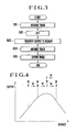
- Fig. 4 is a graph for explaining the operation of the ATF control.
- the axis of abscissa shows the head advancing position.
- the axis of ordinate shows the output of the head.
- the head is assumed to be moved from one track to another track. Then, assuming that the head is first moved to a position A which is close to the desired track (a maximum output position), for example, the output of the head obtained at the position A is stored. After that, the head is moved to a very small extent (fine advancing), and an output thus obtained is compared with the previously stored output.
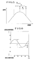
- Fig. 5 shows a case where the head happens to be brought by the first step of the head advancing action to a point at which the output of the head becomes a maximum value.
- a total period of 6 V is necessary even in this case, because the head must be still moved in the sequence of positions A - B - C - D.
- the above-stated head advancing and positioning mechanism requires an excessively long period of time for obtaining the reproduced image, because the ATF control action must be performed twice.
- a disc drive device arranged as a preferred embodiment of this invention is characterized in that the head is mounted on a head carriage with a moving member which is arranged to be capable of occupying any of two positions spaced at a distance corresponding to one track pitch of a recording medium.
- a disc drive device arranged as a preferred embodiment of this invention is characterized in that no ATF control is performed in shifting the head to an adjacent track from a track for which the head has been positioned by the ATF control.
- FIG. 8 is a plan view showing the essential parts of the head advancing mechanism of Fig. 7.
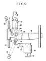
- Fig. 9 is a plan view showing also the essential parts of the same head advancing mechanism.
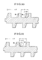
- Figs. 10 and 11 respectively show a positional relation between a lead-screw bar and a pin disposed on the side of a head carriage.
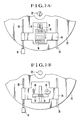
- Fig. 1(A) shows in outline the arrangement of an embodiment of this invention.
- the illustration includes a field head 10; a head support member 12 which is arranged to support the field head 10; an urging spring 14; an electromagnet 16; a driving motor 18; a lead-screw bar 20 which is arranged to be rotated by the driving motor 18; the rotary shaft 22 of a spindle motor which is arranged to rotate a still video floppy disc 23; a carriage 24 which is arranged to convey, by the rotation of the lead-screw bar 20, the field head 10, the head support member 12, the urging spring 14 and the electromagnet 16 altogether in the radial direction of the still video floppy disc 23; a guide bar 26 which is arranged in parallel with the lead-screw bar 20 to guide the carriage 24.
- the lead-screw bar 20 is rotated by the driving motor 18 to move the carriage 24, i.e., the field head 10, in the radial direction of the floppy disc 23.
- the head 10 in performing frame recording, the head 10 is first advanced in a normal manner to one of two recording tracks, and the recording is performed for one of two fields of a frame-recording image. After that, a current is applied to the electromagnet 16. With the electromagnet 16 thus energized, the head 10 is moved against the urging spring 14 toward the outer circumference side of the floppy disc 23 as much as a distance which corresponds to one track pitch. In this new head position, the other field of the frame-recording image is recorded and, after that, the power supply to the electromagnet 16 is brought to a stop. The head 10 and the head support member 12 are brought back to their original positions by the force of the urging spring 14.
- the cam 38 is caused to rotate to move the head 30 and the head support member 32 against the force of the urging spring 36 toward the outer circumference side of the floppy disc 23 as much as one track pitch.
- the other field of the frame-recording image is then recorded at the new position thus obtained.
- the cam 38 is caused to further rotate to bring the head 30 and the head support member 32 back to their original positions by means of the urging spring 36.
- a recording circuit 4 is arranged to carry out predetermined processes such as an emphasis process, a frequency modulation process, etc., on the luminance signal Y and the chrominance signal C output from the camera signal processing circuit 3 to convert them into a signal form suited for recording on a magnetic disc and to supply its output to a head H.
- a reproducing circuit 5 is arranged to carry out a frequency demodulation process, a deemphasis process, etc., on a signal reproduced by the head H to bring the reproduced signal into the original video signal and to supply the reproduced video signal to a monitor or the like which is not shown.
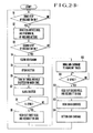
- Fig. 2(B) is a flow chart showing the operation of the camera shown in Fig. 2(A).
- the flow of operation is described below on the assumption that the power supply of the camera has already been turned on and that the head has already been set in its initially set position for an unrecorded track with the power supply turned on:
- the flow waits for the first step of pushing operation on the release switch at a step S1.
- the release switch is pushed to a first step point
- the flow proceeds to a step S2.
- the motor M is driven to rotate the disc.
- the image sensor 2 is driven to begin to take in an image.
- An AE (automatic exposure) circuit, an AF (automatic focusing) circuit and an AWB (automatic white balance) circuit which are not shown are driven into a stand-by state before shooting.
- step S10 The sub-carriage driving circuit 9 is driven to move only the head support member 12 or 32 to an adjacent track, without moving the head carriage 24 or 34.
- step S11 The flow waits for arrival of the V-sync signal. Upon arrival of the V-sync signal, the flow proceeds to a step S12.
- step S12 A signal for the second field is read out. The second field is subjected to the predetermined processing action and is recorded in a recording track on the disc. After completion of this, the flow proceeds to a step S13.
- the main carriage driving circuit 8 is driven to move the head carriage 24 or 34 to the next unrecorded track.
- the sub-carriage 12 or 32 is brought back to its previous state and, after that, the flow comes back to the step S1 to wait for a next shot. As for a reproducing operation, it will be described for a third embodiment which will be described later.
- Fig. 3 is a flow chart showing the operation of the third embodiment.
- the head advancing mechanism of the kind arranged to be capable of advancing the head in a stepless manner uses a cam or a lead-screw bar.
- the advancing precision of the mechanism is considered to be as follows:
- Fig. 6 shows the track precision attained by the ordinary advancing mechanism of the kind using a cam. As shown, a curve representing the track advancing precision is continuous. The curve is smooth if the cam face is smoothly finished.
- a reference symbol P denotes an overall degree of track precision.
- a symbol Q denotes pitch precision between adjacent tracks. Compared with the overall degree of precision, the pitch precision between adjacent tracks can be considered much better. Therefore, the ATF control is considered to be safely omissible in moving the head from one track to an adjacent track.
- the third embodiment is arranged to permit a frame-recording image to be speedily reproduced by a field head.
- the electronic still camera is arranged to record a video signal for one field in one track and, in the case of a frame-recording image, to use two adjacent tracks. Therefore, in cases where a single magnetic head is arranged to be used for frame recording and also for frame reproduction, the magnetic head must be moved and positioned to an adjacent track within a limited period of time other than the time for video image part of the field video signal.
- each of the recording, reproducing and erasing magnetic heads or photo-pickups is hereinafter called the recording/reproducing head or simply as the head.
- the head can be instantly moved from one track to an adjacent track. If the groove is manufactured to have a precise width of the play, the head can be positioned over the adjacent track with a sufficient degree of precision. Therefore, the embodiment has a sufficient head moving speed with an adequate degree of head positioning precision.
- Fig. 7 is an exploded oblique view of the electronic still camera to which the fourth embodiment of the invention is applied.
- Figs. 8 and 9 are plan views showing in part the arrangement of the same camera.
- a carriage 110 has a magnetic head of one channel secured thereto (not shown).
- Shafts 112 which are secured to the carriage 110 extend from both ends of the carriage 110. These shafts 112 are inserted into bearings 114. These bearings 114 are secured to a box-shaped frame which is not shown.
- the carriage 110 is thus supported in a state of being slidable in the directions of the shafts 112.
- a lead-screw bar 116 is rotatably mounted on the box-shaped frame which is not shown.
- An interlocking plate 142 is interlocked with the carriage 110 in a manner which will be described later.
- An armature 146 is rotatably mounted on a shaft 144 which is erected on the interlocking plate 142.
- the armature 146 is set in a position to interfere with a pin 148 which is erected on the lower side of the slide plate 134.
- An electromagnet 150 is secured via a support plate 152 to the interlocking plate 142.
- a pin 154 which is secured to the interlocking plate 142 is inserted into the groove of the lead-screw bar 116.
- a spring 156 is arranged to urge the interlocking plate 142 in the direction of arrow P.
- Fig. 8 shows in a plan view a condition obtained when the head is brought to the desired track position by the rotation of the stepper motor 128. Under this condition, the carriage 110 is being urged in the direction of arrow P by the engagement of the pin 136 with the slot 134a of the slide plate 134 and by the force of the spring 140.
- the positional relation of the groove of the lead-screw bar 116 to the pin 118 is as shown in Fig. 10.
- a reference symbol L denotes the width of the groove of the lead-screw bar 116 in the axial direction thereof.
- a symbol D denotes the diameter of the pin 118 as viewed in the axial direction of the lead-screw bar 116.
- the embodiment can be easily modified by simply changing the dimension of the diameter D of the pin 118 to make the difference (L - D) correspond to the two-track-pitch distance.
- the embodiment permits the head not only to be precisely moved to a predetermined distance point but also to be moved at a high speed.
- a disc drive device has a head mounted on a head carriage with a head moving support mechanism which is capable of moving the head to the extent of one track pitch.
- the device is arranged to advance the head for a plurality of recording tracks on a disc-shaped recording medium at the pitch of two frame-recording tracks.
- the head is moved from one track position to an adjacent track by the head moving support mechanism.
Landscapes
- Moving Of Heads (AREA)
- Moving Of Head For Track Selection And Changing (AREA)
Applications Claiming Priority (6)
| Application Number | Priority Date | Filing Date | Title |
|---|---|---|---|
| JP8348390A JPH03283145A (ja) | 1990-03-30 | 1990-03-30 | ディスク・ドライブ装置 |
| JP8348490A JPH03283149A (ja) | 1990-03-30 | 1990-03-30 | トラック送り制御方法 |
| JP83484/90 | 1990-03-30 | ||
| JP83483/90 | 1990-03-30 | ||
| JP17876790A JPH0467478A (ja) | 1990-07-06 | 1990-07-06 | ディスク・ドライブ装置 |
| JP178767/90 | 1990-07-06 |
Publications (3)
| Publication Number | Publication Date |
|---|---|
| EP0449314A2 true EP0449314A2 (de) | 1991-10-02 |
| EP0449314A3 EP0449314A3 (en) | 1993-12-29 |
| EP0449314B1 EP0449314B1 (de) | 1998-12-09 |
Family
ID=27304238
Family Applications (1)
| Application Number | Title | Priority Date | Filing Date |
|---|---|---|---|
| EP91105077A Expired - Lifetime EP0449314B1 (de) | 1990-03-30 | 1991-03-28 | Plattenlaufwerk |
Country Status (3)
| Country | Link |
|---|---|
| US (1) | US5313446A (de) |
| EP (1) | EP0449314B1 (de) |
| DE (1) | DE69130584T2 (de) |
Cited By (1)
| Publication number | Priority date | Publication date | Assignee | Title |
|---|---|---|---|---|
| EP0789906A4 (de) * | 1994-10-18 | 1997-09-10 |
Families Citing this family (5)
| Publication number | Priority date | Publication date | Assignee | Title |
|---|---|---|---|---|
| JPH10293932A (ja) * | 1997-04-17 | 1998-11-04 | Mitsumi Electric Co Ltd | 光ディスク駆動装置における光ピックアップのスキュー調整機構 |
| US6782547B1 (en) * | 1998-07-02 | 2004-08-24 | Matsushita Electric Industrial Co., Ltd. | Disk drive with slider pressure plate |
| US20040117807A1 (en) * | 2001-03-01 | 2004-06-17 | Shoji Takahashi | Disk drive device |
| US8321439B2 (en) * | 2004-12-17 | 2012-11-27 | Microsoft Corporation | Quick filename lookup using name hash |
| JP4603478B2 (ja) * | 2005-12-06 | 2010-12-22 | 株式会社日立製作所 | 光ディスク装置 |
Family Cites Families (11)
| Publication number | Priority date | Publication date | Assignee | Title |
|---|---|---|---|---|
| US3924268A (en) * | 1974-08-05 | 1975-12-02 | Ibm | High density track follower control system for magnetic disk file |
| ATE114378T1 (de) * | 1981-10-28 | 1994-12-15 | Discovision Ass | Verfahren zur wiedergabe von informationen von einer ausgewählten spur einer aufzeichnungsplatte. |
| US4831615A (en) * | 1985-01-30 | 1989-05-16 | Nippon Columbia Co., Ltd. | Dual differential optical system moving apparatus |
| US5051849A (en) * | 1985-11-28 | 1991-09-24 | Canon Kabushiki Kaisha | Recording apparatus including a pre-recording positioning function |
| JPH01191382A (ja) * | 1988-01-26 | 1989-08-01 | Mitsubishi Electric Corp | 磁気ヘッド位置設定方式 |
| KR910007482B1 (ko) * | 1988-03-18 | 1991-09-26 | 가부시끼가이샤 히다찌세이사꾸쇼 | 리니어 액세스기구와 자기디스크장치 |
| JP2724335B2 (ja) * | 1988-10-28 | 1998-03-09 | キヤノン株式会社 | ガイドレール取付構造 |
| JPH02149983A (ja) * | 1988-11-30 | 1990-06-08 | Nikon Corp | オートトラッキング装置 |
| JPH02177065A (ja) * | 1988-12-27 | 1990-07-10 | Matsushita Electric Ind Co Ltd | 支持装置 |
| JPH0340250A (ja) * | 1989-07-06 | 1991-02-21 | Matsushita Electric Ind Co Ltd | 光磁気ディスクおよび光磁気ディスク装置 |
| US5189660A (en) * | 1991-05-09 | 1993-02-23 | Tandy Corporation | Optical data storage system with unitary ferrous frame |
-
1991
- 1991-03-25 US US07/674,665 patent/US5313446A/en not_active Expired - Fee Related
- 1991-03-28 DE DE69130584T patent/DE69130584T2/de not_active Expired - Fee Related
- 1991-03-28 EP EP91105077A patent/EP0449314B1/de not_active Expired - Lifetime
Cited By (1)
| Publication number | Priority date | Publication date | Assignee | Title |
|---|---|---|---|---|
| EP0789906A4 (de) * | 1994-10-18 | 1997-09-10 |
Also Published As
| Publication number | Publication date |
|---|---|
| DE69130584D1 (de) | 1999-01-21 |
| DE69130584T2 (de) | 1999-06-17 |
| EP0449314B1 (de) | 1998-12-09 |
| EP0449314A3 (en) | 1993-12-29 |
| US5313446A (en) | 1994-05-17 |
Similar Documents
| Publication | Publication Date | Title |
|---|---|---|
| US4224481A (en) | Compression and expansion circuitry for a recording and playback system | |
| DE2711924A1 (de) | Optisches aufzeichnungs/wiedergabegeraet | |
| DE2711923A1 (de) | Optisches aufzeichnungs/wiedergabegeraet | |
| US4495609A (en) | Recording and playback system | |
| US20030133033A1 (en) | Image-taking lens system | |
| US5313446A (en) | Disc drive device having a head carriage | |
| KR980011109A (ko) | 광 기록 재생 장치 | |
| US5617391A (en) | Optical recording and reproducing system | |
| US5381399A (en) | Head shifting apparatus | |
| KR850001484B1 (ko) | 비데오 기록-재생 장치의 구동 장치 | |
| US5684919A (en) | Recording apparatus for a video signal and a control information indicative of a control state of a video camera | |
| US5012374A (en) | Recording and/or reproducing apparatus in which the position of head means relative to the record bearing medium is controlled between two positions | |
| JPH0359510B2 (de) | ||
| US4700335A (en) | Method and apparatus for recording a continuous spiral information track with different track pitches | |
| US4418365A (en) | Video disc transducer system | |
| US4829394A (en) | Device for detecting reference position of magnetic head | |
| JP3715959B2 (ja) | 撮像装置、その制御方法、及び制御プログラム | |
| US5198941A (en) | Recording or reproducing apparatus | |
| JP3254809B2 (ja) | 磁気記録再生装置 | |
| JPH0961695A (ja) | レンズ駆動装置 | |
| JPH02143961A (ja) | ヘッド移動装置 | |
| JP2582379B2 (ja) | 記録情報消去装置 | |
| JPH01292678A (ja) | 記録/再生装置 | |
| JPS62285278A (ja) | デイスク駆動装置 | |
| JP3070208B2 (ja) | ディスク再生又は記録装置 |
Legal Events
| Date | Code | Title | Description |
|---|---|---|---|
| PUAI | Public reference made under article 153(3) epc to a published international application that has entered the european phase |
Free format text: ORIGINAL CODE: 0009012 |
|
| AK | Designated contracting states |
Kind code of ref document: A2 Designated state(s): DE FR GB |
|
| PUAL | Search report despatched |
Free format text: ORIGINAL CODE: 0009013 |
|
| AK | Designated contracting states |
Kind code of ref document: A3 Designated state(s): DE FR GB |
|
| 17P | Request for examination filed |
Effective date: 19940511 |
|
| 17Q | First examination report despatched |
Effective date: 19941223 |
|
| GRAG | Despatch of communication of intention to grant |
Free format text: ORIGINAL CODE: EPIDOS AGRA |
|
| GRAG | Despatch of communication of intention to grant |
Free format text: ORIGINAL CODE: EPIDOS AGRA |
|
| GRAH | Despatch of communication of intention to grant a patent |
Free format text: ORIGINAL CODE: EPIDOS IGRA |
|
| GRAH | Despatch of communication of intention to grant a patent |
Free format text: ORIGINAL CODE: EPIDOS IGRA |
|
| GRAA | (expected) grant |
Free format text: ORIGINAL CODE: 0009210 |
|
| AK | Designated contracting states |
Kind code of ref document: B1 Designated state(s): DE FR GB |
|
| PG25 | Lapsed in a contracting state [announced via postgrant information from national office to epo] |
Ref country code: FR Free format text: LAPSE BECAUSE OF FAILURE TO SUBMIT A TRANSLATION OF THE DESCRIPTION OR TO PAY THE FEE WITHIN THE PRESCRIBED TIME-LIMIT Effective date: 19981209 |
|
| REF | Corresponds to: |
Ref document number: 69130584 Country of ref document: DE Date of ref document: 19990121 |
|
| PG25 | Lapsed in a contracting state [announced via postgrant information from national office to epo] |
Ref country code: GB Free format text: LAPSE BECAUSE OF NON-PAYMENT OF DUE FEES Effective date: 19990328 |
|
| EN | Fr: translation not filed | ||
| PLBE | No opposition filed within time limit |
Free format text: ORIGINAL CODE: 0009261 |
|
| STAA | Information on the status of an ep patent application or granted ep patent |
Free format text: STATUS: NO OPPOSITION FILED WITHIN TIME LIMIT |
|
| GBPC | Gb: european patent ceased through non-payment of renewal fee |
Effective date: 19990328 |
|
| 26N | No opposition filed | ||
| PGFP | Annual fee paid to national office [announced via postgrant information from national office to epo] |
Ref country code: DE Payment date: 20050324 Year of fee payment: 15 |
|
| PG25 | Lapsed in a contracting state [announced via postgrant information from national office to epo] |
Ref country code: DE Free format text: LAPSE BECAUSE OF NON-PAYMENT OF DUE FEES Effective date: 20061003 |