EP0449121A2 - Optisches Aufzeichnungsmedium und Aufzeichnungs-/Wiedergabemethode dafür - Google Patents
Optisches Aufzeichnungsmedium und Aufzeichnungs-/Wiedergabemethode dafür Download PDFInfo
- Publication number
- EP0449121A2 EP0449121A2 EP91104467A EP91104467A EP0449121A2 EP 0449121 A2 EP0449121 A2 EP 0449121A2 EP 91104467 A EP91104467 A EP 91104467A EP 91104467 A EP91104467 A EP 91104467A EP 0449121 A2 EP0449121 A2 EP 0449121A2
- Authority
- EP
- European Patent Office
- Prior art keywords
- light
- heat
- recording
- absorbing
- recording medium
- Prior art date
- Legal status (The legal status is an assumption and is not a legal conclusion. Google has not performed a legal analysis and makes no representation as to the accuracy of the status listed.)
- Granted
Links
Images

Classifications
-
- G—PHYSICS
- G11—INFORMATION STORAGE
- G11B—INFORMATION STORAGE BASED ON RELATIVE MOVEMENT BETWEEN RECORD CARRIER AND TRANSDUCER
- G11B7/00—Recording or reproducing by optical means, e.g. recording using a thermal beam of optical radiation by modifying optical properties or the physical structure, reproducing using an optical beam at lower power by sensing optical properties; Record carriers therefor
- G11B7/24—Record carriers characterised by shape, structure or physical properties, or by the selection of the material
-
- G—PHYSICS
- G11—INFORMATION STORAGE
- G11B—INFORMATION STORAGE BASED ON RELATIVE MOVEMENT BETWEEN RECORD CARRIER AND TRANSDUCER
- G11B7/00—Recording or reproducing by optical means, e.g. recording using a thermal beam of optical radiation by modifying optical properties or the physical structure, reproducing using an optical beam at lower power by sensing optical properties; Record carriers therefor
- G11B7/004—Recording, reproducing or erasing methods; Read, write or erase circuits therefor
- G11B7/0045—Recording
-
- Y—GENERAL TAGGING OF NEW TECHNOLOGICAL DEVELOPMENTS; GENERAL TAGGING OF CROSS-SECTIONAL TECHNOLOGIES SPANNING OVER SEVERAL SECTIONS OF THE IPC; TECHNICAL SUBJECTS COVERED BY FORMER USPC CROSS-REFERENCE ART COLLECTIONS [XRACs] AND DIGESTS
- Y10—TECHNICAL SUBJECTS COVERED BY FORMER USPC
- Y10S—TECHNICAL SUBJECTS COVERED BY FORMER USPC CROSS-REFERENCE ART COLLECTIONS [XRACs] AND DIGESTS
- Y10S430/00—Radiation imagery chemistry: process, composition, or product thereof
- Y10S430/146—Laser beam
Definitions
- the present invention generally relates to an optical recording/reproducing method for recording/reproducing an image, audio information, or the like in accordance with optical information, and particularly relates to an optical recording medium and a recording/reproducing method making it possible to perform high density recording/reproducing.
- optical disks such as an audio compact disk (CD), a video disk (VD), and the like, on which recording/-reproducing of optical information can be performed have been very widely used.
- an optical disk recording can be made with much greater density, one or two orders of magnitude, than a magnetic recording because the signal is recorded/reproduced using a small light spot having a size of about the wavelength of light.
- an optical disk has a signal surface which is not worn during use so that it is superior in non-volatility of recording (holding of recorded data) because the reproduction of the recorded information is performed by a noncontact method using a light beam.
- the signal is recorded as a series of binary values indicated by whether a hole (pit) exists or not in a light reflection surface of the disk, and information is expressed by a pit length (size) and a pit interval.
- a pit length size
- a pit interval discretely vary.
- analog recording generally, although any signal can be recorded so as to obtain an extremely high information packing density, there is a problem concerning the accuracy of the recorded signal and the accuracy of signal reproduction whereby noise in optical and electric systems directly affects the signal-to-noise ratio of the reproduced signal.
- the recorded information can be accurately reproduced if the mark length can be discriminated. Further, digital recording has the advantage that even if a certain amount of error exists, the original correct information can be restored using an error correcting code. In digital recording, however, since the mark size must be discretely distributed within a predetermined range of length as described above, the number of marks is unavoidably limited, and it is therefore a matter of course that the recording density is limited.
- the changes in the recording signal are difficult to distinguish from the case where the signal changes in a continuous manner.
- the method is therefore not significantly different from the previously described conventional techniques. More specifically, multi-valuing is carried out using a plurality of threshold values of the quantity of recording light as determined by changes in the recording spot diameter.
- the output power level of the recording signal beam generating laser generally unavoidably fluctuates in a range of about 1 to 2 mW, so that an error is caused in the recorded mark diameter. Since as the number of available multi-level values is increased the intervals of the threshold values become less, at a certain number of multi-value levels the fluctuations in the recording beam power level make it impossible to accurately distinguish between adjacent recorded levels.
- An object of the present invention is to solve the foregoing problems in the prior art and to provide an optical recording medium and a recording/reproducing method in which a signal, which can be multi-valued, can be very accurately written and read out.
- an optical recording medium characterized in that a recording layer group and a light-absorbing and heat-generating layer for absorbing radiated light to convert the absorbed light into heat are formed on a substrate, the recording layer group being formed of thermo-sensitive recording layers capable of recording therein information in the form of a light signal and heat insulating layers, the thermo-sensitive recording layers and the heat insulating layers being alternately stacked one-on-one in three or more layers, and the light-absorbing and heat-generating layer being formed in a position so as to contact the recording layer group.
- the foregoing object of the present invention can also be attained by a method using the foregoing recording medium, that is, by a method of recording/reproducing optical information in which a light-absorbing and heat-generating layer for absorbing specified light to convert the absorbed light into heat is irradiated with laser light focused on the light-absorbing and heat-generating layer, and in which, by use of a recording layer group disposed adjacent to the light-absorbing and heat-generating layer and formed of thermo-sensitive recording layers and heat insulating layers alternately stacked one on one in layers, a multi-valued signal pattern is recorded based on stepwise concentration changes of the thermo-sensitive recording layers due to modulation of the laser light.
- Fig. 1 is a partial sectional view showing an optical disk, which is an optical recording medium according to the present invention.
- thermal-sensitive recording layers 3 n and heat insulating layers 4 n are alternately stacked one-on-one in plural layers so as to form a signal recording layer group 6 on a transparent substrate 2.
- the recording layer group 6 is constituted by four recording layers 3 n (31, 32, 33, and 34) and four heat insulating layers 4 n (41, 42, 43, and 44).
- a light-absorbing and heat-generating layer 5 for absorbing radiated light to convert the absorbed light into heat is formed on the recording layer group 6, and a flat reflection layer 7 made, for example, of aluminum, gold, silver, or the like is formed on the light-absorbing heat-generating layer 5 through the heat insulating layer 45.
- the reflection layer 7 is formed by an evaporation method, a sputtering method, or the like.
- Each thermal-sensitive recording layer 3 n may be formed, for example, of a phase-change material such as InSe or an imidazoquinoxaline-type coloring material so that the layer is colored by application of heat.
- each heat insulating layer 4 n is disposed between two thermal-sensitive recording layers 2 and has the function of suitably controlling heat transmission between the thermal-sensitive recording layers 3 n .
- Each heat insulating layer 4 n may be formed, for example, of a high molecular material such as silicon oxide (SiO2), Teflon, or the like. Further, each heat insulating layer 4 n is transparent.
- the light-absorbing heat-generating layer 5 may be formed, for example, of a cyaninedie or the like so as to effectively generate heat by light illuminated onto the layer.
- Laser light L B emitted from a luminous source of a recording apparatus is condensed through an objective lens 10 so as to be focused on the light-absorbing and heat-generating layer 5.
- the light-absorbing and heat-generating layer 5 absorbs the light and generates heat.
- the heat reaches the first recording layer 31, overcoming the heat insulating ability of the first heat insulating layer 41.
- the first recording layer 31 is colored, the second recording layer 32 adjacent thereto is not colored because of the heat insulating function of the second heat insulating layer 32.
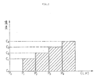
- the writing accuracy of the recorded signal is made extremely high due to the lack of any effect caused by fluctuations of the laser power. That is, it is possible to prevent generation of defective recording caused by fluctuations in the laser light output because the width of the laser power (LP) from the first critical point to the second critical point is very large in comparison with the magnitude of the fluctuations in the output of the writing laser beam, as indicated in Fig. 2.
- a signal corresponding to a first concentration level C1 in Fig. 2 can be written by maintaining the laser power P n in the range of P1 ⁇ P n ⁇ P2, as described above.
- the second concentration level C2 In order to establish the second concentration level C2, it suffices to make the quantity of light intensive by modulating the laser light L B or to prolong the time of radiation of the laser light L B to thereby make the heat reach the second recording layer 32. In this manner, by adjusting the quantity of light as described above (the same applies to the other points P2, P3, and P4), the third and fourth recording layers 33 and 34 can be successively colored. Thus, it is possible to perform writing in the state where the concentration levels are clearly separated into five stages from C0 to C4.
- thermo-sensitive recording layers 3 n and the heat insulating layers 4 n are alternately stacked one-by-one in plural layers adjacent to the light-absorbing and heat-generating layer 5, as described above. Accordingly, when the heat generated in the light-absorbing and heat-generating layer 5 is transmitted in the direction of the thickness of the recording layer group 6, the heat insulating functions of the respective heat insulating layers 4 n can clearly discriminate changes of heat between the recording layers, that is, the respective heat insulating layers act as threshold values, which do not cause misidentification of signals. Consequently, recording and reproducing can be performed to obtain a very clear signal on the basis of a multi-valued signal pattern by discrete changes in concentration in the recording layer group 6 utilizing changes in the number of recording layers. This is accomplished without changing the size of the recording mark.
- the reflection layer 7 is irradiated with the reading laser light, and a read-out signal is produced on the basis of the quantity of the reflected light.
- the signal can be reproduced as the stepwise discrete signals (C0, C1, C2, C3, and C4). Therefore, slight fluctuations of the laser light output during the recording operation will not affect the quality of the recorded signal. Accordingly, not only is the discrimination of the signal good so as to make the recording reliability high, but it is also possible to accurately reproduce the stored information even if the accuracy of a reproducing apparatus is not particularly high.
- the coloring of the recording layers 3 n is not limited to colors within the visible spectrum, but it is a matter of course that wavelengths other than those within the visible spectrum be used. That is, the coloring is not specifically limited. This is because, for example, a layer change in a recording layer which easily absorbs laser light in the reproducing operation can be regarded as coloring. Thus, it is possible to produce an effective difference in concentration by changing the substance of the recording layer so that it can easily absorb wavelengths equal to or approximate to that of the laser light used for reproducing.
- the heat insulating layer 4 may also function to prevent heat generated in the light-absorbing and heat-generating layer 5 from escaping to the side of the reflection layer 7.
- the present invention is not limited to this arrangement, and, for example, the configuration may be such that the light-absorbing and heat-generating layer 5 is disposed so as to be closer to the substrate than the recording layers 3 n , or disposed inside of the recording layer group 6.
- a five-valued signal is used in this embodiment, it is a matter of course that more than five levels can be used.
- a three-valued signal can be obtained in the case of providing two recording layers; generally, when an N-valued signal is required, it suffices to provide (N-1) recording layers.
- the recording medium according to the present invention is not limited to that for exclusive use for reproducing, but it is a matter of course that the recording medium can be a write-once type.
- the recording medium in this embodiment has a configuration in which the reflection layer 7 is provided, the present invention is not limited to this arrangement. That is, the reflection layer 7 may be eliminated if desired.
- the recording medium may have a configuration in which the recording layer group 6 is sandwiched between light-permissible supports (substrates), and a recording signal is detected by detecting the quantity of light of the light transmitted through the recording layer group 6, so that it is possible to exceedingly accurately obtain a reproduced signal.
- an optical recording medium in which a recording layer group and a light-absorbing and heat-generating layer for absorbing radiated light to convert the absorbed light into heat are formed on a substrate.
- the recording layer group is formed of thermo-sensitive recording layers capable of recording thereon information in the form of a light signal and heat insulating layers.
- the thermo-sensitive recording layers and the heat insulating layers being alternately stacked in plural layers, the light-absorbing and heat-generating layer being formed in a position so as to contact the recording layer group.
- laser light emitted from a luminous source in a recording apparatus is condensed through an objective lens so as to be focused on the light-absorbing and heat-generating layer, so that when heat of a predetermined quantity or more is generated by the light-absorbing and heat-generating layer, the heat reaches the recording layers successively stepwise due to the heat insulating functions of the respective heat insulating layers.
- a multi-valued signal can be digitally expressed.
- a very clear signal can be recorded in the form of a signal pattern on the basis of a stepwise change of concentration in the recording layer group utilizing a change of the number of recorded layers, that is, a change in the mark depth direction, and the thus-recorded signal can be reads as a signal having a stepwise clear concentration difference.
Landscapes
- Optical Recording Or Reproduction (AREA)
- Thermal Transfer Or Thermal Recording In General (AREA)
- Optical Record Carriers And Manufacture Thereof (AREA)
Applications Claiming Priority (2)
| Application Number | Priority Date | Filing Date | Title |
|---|---|---|---|
| JP2075680A JPH03275382A (ja) | 1990-03-27 | 1990-03-27 | 光記録媒体及び記録再生方法 |
| JP75680/90 | 1990-03-27 |
Publications (3)
| Publication Number | Publication Date |
|---|---|
| EP0449121A2 true EP0449121A2 (de) | 1991-10-02 |
| EP0449121A3 EP0449121A3 (en) | 1992-08-05 |
| EP0449121B1 EP0449121B1 (de) | 1995-07-05 |
Family
ID=13583157
Family Applications (1)
| Application Number | Title | Priority Date | Filing Date |
|---|---|---|---|
| EP91104467A Expired - Lifetime EP0449121B1 (de) | 1990-03-27 | 1991-03-21 | Optisches Aufzeichnungsmedium und Aufzeichnungs-/Wiedergabemethode dafür |
Country Status (4)
| Country | Link |
|---|---|
| US (1) | US5419999A (de) |
| EP (1) | EP0449121B1 (de) |
| JP (1) | JPH03275382A (de) |
| DE (1) | DE69110933T2 (de) |
Cited By (7)
| Publication number | Priority date | Publication date | Assignee | Title |
|---|---|---|---|---|
| EP0596339A1 (de) * | 1992-11-02 | 1994-05-11 | Pioneer Electronic Corporation | Optisches Aufzeichnungsmedium |
| EP1202285A3 (de) * | 2000-10-27 | 2004-01-02 | Matsushita Electric Industrial Co., Ltd. | Speicher, Verfahren und Anordnung zum Schreiben und Lesen |
| WO2003100702A3 (en) * | 2002-05-24 | 2004-10-28 | Sony Corp | Disc-shaped recording medium, disc driving device and disc producing method |
| US6998289B2 (en) | 2001-08-31 | 2006-02-14 | Intel Corporation | Multiple layer phase-change memory |
| EP1484757A3 (de) * | 2003-06-06 | 2006-05-24 | Sharp Kabushiki Kaisha | Optischer Datenaufzeichnungsträger, Verfahren zum Aufzeichnen und zum Lesen worin genannter Datenaufzeichnungsträger eingesetzt wird, Vorrichtung für optische Datenaufzeichnung und Vorrichtung zum Lesen von optischen Daten |
| US7556912B2 (en) | 2003-06-06 | 2009-07-07 | Sharp Kabushiki Kaisha | Optical information recording medium, reproducting method using the same, and optical information processing device |
| US8189449B2 (en) | 2007-03-07 | 2012-05-29 | Ricoh Company, Ltd. | Multilayer optical information medium and optical information processing apparatus therefor, program product and information medium including the same |
Families Citing this family (10)
| Publication number | Priority date | Publication date | Assignee | Title |
|---|---|---|---|---|
| JP3442827B2 (ja) * | 1993-09-22 | 2003-09-02 | 株式会社東芝 | 記憶媒体及びその記録処理方法 |
| JP3529969B2 (ja) * | 1997-02-26 | 2004-05-24 | 株式会社東芝 | 多値相変化光記録媒体 |
| US6421303B1 (en) * | 1997-11-14 | 2002-07-16 | Fujitsu Limited | Multilayer resonance device and magneto-optical recording medium with magnetic center layer of a different thickness than that of the components of the reflecting layers, and method of reproducing the same |
| KR100338756B1 (ko) * | 1999-07-20 | 2002-05-30 | 윤종용 | 상변화 광디스크 |
| JP4106417B2 (ja) * | 2002-05-16 | 2008-06-25 | 三星電子株式会社 | 高融点の記録層を有する記録媒体及びその記録媒体の情報記録方法、及びその記録媒体から情報を再生する情報再生装置及び情報再生方法 |
| US20060120256A1 (en) * | 2003-02-25 | 2006-06-08 | Matsushita Electric Industrial Co., Ltd | Optical information recording carrier |
| KR20050000108A (ko) * | 2003-06-23 | 2005-01-03 | 삼성전자주식회사 | 초해상 근접장 구조를 가지는 광디스크 |
| KR20070037502A (ko) * | 2004-07-07 | 2007-04-04 | 코닌클리케 필립스 일렉트로닉스 엔.브이. | 정보의 기록매체에의 멀티레벨 기록방법, 기록매체 및기록장치 |
| WO2012003247A2 (en) * | 2010-06-30 | 2012-01-05 | 3M Innovative Properties Company | Multi-layer articles capable of forming color images and methods of forming color images |
| EP2588317B1 (de) * | 2010-06-30 | 2020-03-18 | 3M Innovative Properties Company | Zur bildung von farbbildern fähige mehrschichtige gegenstände und verfahren zur bildung von farbbildern |
Family Cites Families (22)
| Publication number | Priority date | Publication date | Assignee | Title |
|---|---|---|---|---|
| US4090031A (en) * | 1974-10-21 | 1978-05-16 | Eli S. Jacobs | Multi-layered opitcal data records and playback apparatus |
| US4219704A (en) * | 1974-10-21 | 1980-08-26 | Eli S. Jacobs | Record playback apparatus for optical data records |
| JPS5674843A (en) * | 1979-11-21 | 1981-06-20 | Fuji Photo Film Co Ltd | Photomagnetic recording medium |
| US4460636A (en) * | 1981-03-27 | 1984-07-17 | Sony Corporation | Optical information record member |
| US4451914A (en) * | 1982-04-15 | 1984-05-29 | Burroughs Corporation | Optical storage system employing a multi-layer optical medium |
| US4584259A (en) * | 1982-12-17 | 1986-04-22 | Burroughs Corporation | Coated media for optical recording with acrylic overcoat |
| US4547444A (en) * | 1983-12-23 | 1985-10-15 | Minnesota Mining And Manufacturing Company | Recording element for optical data storage |
| US4718053A (en) * | 1984-11-09 | 1988-01-05 | Hitachi, Ltd. | Optical information apparatus and method of recording and erasing information |
| US4651172A (en) * | 1984-11-29 | 1987-03-17 | Hitachi, Ltd. | Information recording medium |
| US4568952A (en) * | 1984-12-10 | 1986-02-04 | Rca Corporation | Optical record blank and information record |
| CA1272666A (en) * | 1985-05-15 | 1990-08-14 | Energy Conversion Devices, Inc. | Multilayered article including crystallization inhibiting layer and method for fabricating same |
| US4816287A (en) * | 1985-08-30 | 1989-03-28 | Optical Materials, Inc. | Optical recording media with thermal insulation and method of making the media |
| JPS62222442A (ja) * | 1986-03-22 | 1987-09-30 | Nippon Telegr & Teleph Corp <Ntt> | 書換型光記録媒体 |
| US4860273A (en) * | 1986-07-31 | 1989-08-22 | Fuji Photo Film Co., Ltd. | Method of recording information and information recording medium employed for the same |
| JPS6398854A (ja) * | 1986-10-15 | 1988-04-30 | Matsushita Electric Ind Co Ltd | 光学情報記録担体 |
| JPS63142546A (ja) * | 1986-12-05 | 1988-06-14 | Hitachi Ltd | 波長多重光記録媒体 |
| JPH01149245A (ja) * | 1987-12-03 | 1989-06-12 | Ricoh Co Ltd | 多重記録層を有する光磁気記録媒体及びその記録方法 |
| US4973572A (en) * | 1987-12-21 | 1990-11-27 | Eastman Kodak Company | Infrared absorbing cyanine dyes for dye-donor element used in laser-induced thermal dye transfer |
| JP2588422B2 (ja) * | 1988-05-20 | 1997-03-05 | 富士写真フイルム株式会社 | 光情報記録媒体 |
| US4940618A (en) * | 1988-07-30 | 1990-07-10 | Taiyo Yuden Company, Ltd. | Optical information recording medium |
| US5075147A (en) * | 1989-03-24 | 1991-12-24 | Fuji Photo Film Co., Ltd. | Method for optically recording information and information recorded medium |
| JPH03297689A (ja) * | 1990-04-17 | 1991-12-27 | Toray Ind Inc | 情報記録媒体 |
-
1990
- 1990-03-27 JP JP2075680A patent/JPH03275382A/ja active Pending
-
1991
- 1991-03-21 EP EP91104467A patent/EP0449121B1/de not_active Expired - Lifetime
- 1991-03-21 DE DE69110933T patent/DE69110933T2/de not_active Expired - Fee Related
-
1993
- 1993-12-10 US US08/164,786 patent/US5419999A/en not_active Expired - Lifetime
Cited By (11)
| Publication number | Priority date | Publication date | Assignee | Title |
|---|---|---|---|---|
| EP0596339A1 (de) * | 1992-11-02 | 1994-05-11 | Pioneer Electronic Corporation | Optisches Aufzeichnungsmedium |
| EP1202285A3 (de) * | 2000-10-27 | 2004-01-02 | Matsushita Electric Industrial Co., Ltd. | Speicher, Verfahren und Anordnung zum Schreiben und Lesen |
| US6809401B2 (en) | 2000-10-27 | 2004-10-26 | Matsushita Electric Industrial Co., Ltd. | Memory, writing apparatus, reading apparatus, writing method, and reading method |
| US6998289B2 (en) | 2001-08-31 | 2006-02-14 | Intel Corporation | Multiple layer phase-change memory |
| DE10297115B4 (de) * | 2001-08-31 | 2009-04-09 | Intel Corporation, Santa Clara | Mehrlagiger Phasenübergangsspeicher, insbesondere Speicherzelle und Verfahren zur Herstellung |
| WO2003100702A3 (en) * | 2002-05-24 | 2004-10-28 | Sony Corp | Disc-shaped recording medium, disc driving device and disc producing method |
| US7221644B2 (en) | 2002-05-24 | 2007-05-22 | Sony Corporation | Disc-shaped recording medium, disc driving device and disc producing method |
| EP1484757A3 (de) * | 2003-06-06 | 2006-05-24 | Sharp Kabushiki Kaisha | Optischer Datenaufzeichnungsträger, Verfahren zum Aufzeichnen und zum Lesen worin genannter Datenaufzeichnungsträger eingesetzt wird, Vorrichtung für optische Datenaufzeichnung und Vorrichtung zum Lesen von optischen Daten |
| US7556912B2 (en) | 2003-06-06 | 2009-07-07 | Sharp Kabushiki Kaisha | Optical information recording medium, reproducting method using the same, and optical information processing device |
| US7682678B2 (en) | 2003-06-06 | 2010-03-23 | Sharp Kabushiki Kaisha | Optical information recording medium, recording and readout methods using the same, optical information recording device, and optical information readout device |
| US8189449B2 (en) | 2007-03-07 | 2012-05-29 | Ricoh Company, Ltd. | Multilayer optical information medium and optical information processing apparatus therefor, program product and information medium including the same |
Also Published As
| Publication number | Publication date |
|---|---|
| EP0449121B1 (de) | 1995-07-05 |
| JPH03275382A (ja) | 1991-12-06 |
| DE69110933D1 (de) | 1995-08-10 |
| US5419999A (en) | 1995-05-30 |
| EP0449121A3 (en) | 1992-08-05 |
| DE69110933T2 (de) | 1995-11-23 |
Similar Documents
| Publication | Publication Date | Title |
|---|---|---|
| EP0449121B1 (de) | Optisches Aufzeichnungsmedium und Aufzeichnungs-/Wiedergabemethode dafür | |
| EP0540345B1 (de) | Verfahren zur Aufzeichnung von Information, Verfahren zur Wiedergabe aufgezeichneter Information und Gerät und Aufzeichnunsmedium dafür | |
| US5199023A (en) | Optical information recording medium with a separating part between information tracks | |
| US5614938A (en) | Three-dimensional recording and reproducing apparatus | |
| US4460636A (en) | Optical information record member | |
| EP0092707A2 (de) | Optisches Speichermaterial und ein optisches Mehrschichtelement dafür | |
| US6229771B1 (en) | Method and apparatus for generating focus error signals in a multi-beam optical disk drive | |
| EP0092113A2 (de) | Optisches Speicherelement zur Verwendung in einem optischen Speichersystem sowie ein Verfahren zur Herstellung des Speicherelements | |
| EP1341167B1 (de) | Optisches aufzeichnungsmedium und optisches plattengeraet | |
| US7535804B2 (en) | Apparatus and method for recording an information on a recordable optical record carrier using oval spot profile | |
| EP0083193A1 (de) | Vorrichtung zum Vorformatieren einer optischen Scheibe | |
| KR100303966B1 (ko) | 광학적정보기록매체 | |
| US5546364A (en) | Magneto-optical memory apparatus utilizing edges or recording mark to manage data | |
| JP3173839B2 (ja) | 記録媒体用情報再生装置及び再生方法 | |
| US5467339A (en) | Optical disc having information units comprising a plurality of separated pit pieces, and playback apparatus and recording and playback method therefor | |
| EP0614176A1 (de) | Wiedergabeverfahren und -gerät für optische Platte | |
| JPH0264932A (ja) | 情報記録媒体、それを用いた情報記録装置、及び情報記録方法 | |
| JPH1125456A (ja) | 光記録媒体における多値情報の記録方法及び再生方法 | |
| JP2002245626A (ja) | 情報記録装置及び記録媒体 | |
| JP2778428B2 (ja) | 光ディスク装置 | |
| EP0751505A2 (de) | Optisches Informationsaufzeichnungsmedium | |
| EP1526516B1 (de) | Optisches Aufzeichnungsmedium, Substrat eines optischen Aufzeichnungsmediums und optisches Plattengerät | |
| JP2914732B2 (ja) | 情報再生装置 | |
| JP2829108B2 (ja) | 情報再生装置 | |
| JPH04319531A (ja) | 光情報再生方法及び光情報記録媒体 |
Legal Events
| Date | Code | Title | Description |
|---|---|---|---|
| PUAI | Public reference made under article 153(3) epc to a published international application that has entered the european phase |
Free format text: ORIGINAL CODE: 0009012 |
|
| AK | Designated contracting states |
Kind code of ref document: A2 Designated state(s): DE NL |
|
| PUAL | Search report despatched |
Free format text: ORIGINAL CODE: 0009013 |
|
| AK | Designated contracting states |
Kind code of ref document: A3 Designated state(s): DE NL |
|
| 17P | Request for examination filed |
Effective date: 19921013 |
|
| 17Q | First examination report despatched |
Effective date: 19940912 |
|
| GRAA | (expected) grant |
Free format text: ORIGINAL CODE: 0009210 |
|
| AK | Designated contracting states |
Kind code of ref document: B1 Designated state(s): DE NL |
|
| REF | Corresponds to: |
Ref document number: 69110933 Country of ref document: DE Date of ref document: 19950810 |
|
| PLBE | No opposition filed within time limit |
Free format text: ORIGINAL CODE: 0009261 |
|
| STAA | Information on the status of an ep patent application or granted ep patent |
Free format text: STATUS: NO OPPOSITION FILED WITHIN TIME LIMIT |
|
| 26N | No opposition filed | ||
| PGFP | Annual fee paid to national office [announced via postgrant information from national office to epo] |
Ref country code: NL Payment date: 20080316 Year of fee payment: 18 |
|
| PGFP | Annual fee paid to national office [announced via postgrant information from national office to epo] |
Ref country code: DE Payment date: 20080313 Year of fee payment: 18 |
|
| NLV4 | Nl: lapsed or anulled due to non-payment of the annual fee |
Effective date: 20091001 |
|
| PG25 | Lapsed in a contracting state [announced via postgrant information from national office to epo] |
Ref country code: DE Free format text: LAPSE BECAUSE OF NON-PAYMENT OF DUE FEES Effective date: 20091001 |
|
| PG25 | Lapsed in a contracting state [announced via postgrant information from national office to epo] |
Ref country code: NL Free format text: LAPSE BECAUSE OF NON-PAYMENT OF DUE FEES Effective date: 20091001 |