EP0449037B1 - Positionsgeber - Google Patents
Positionsgeber Download PDFInfo
- Publication number
- EP0449037B1 EP0449037B1 EP91103848A EP91103848A EP0449037B1 EP 0449037 B1 EP0449037 B1 EP 0449037B1 EP 91103848 A EP91103848 A EP 91103848A EP 91103848 A EP91103848 A EP 91103848A EP 0449037 B1 EP0449037 B1 EP 0449037B1
- Authority
- EP
- European Patent Office
- Prior art keywords
- transducer
- fact
- circuit
- pulses
- line
- Prior art date
- Legal status (The legal status is an assumption and is not a legal conclusion. Google has not performed a legal analysis and makes no representation as to the accuracy of the status listed.)
- Expired - Lifetime
Links
- 230000005540 biological transmission Effects 0.000 claims description 5
- 230000005355 Hall effect Effects 0.000 claims description 2
- 235000014676 Phragmites communis Nutrition 0.000 claims description 2
- 238000001208 nuclear magnetic resonance pulse sequence Methods 0.000 claims description 2
- 238000010586 diagram Methods 0.000 description 8
- 238000005259 measurement Methods 0.000 description 4
- 238000000034 method Methods 0.000 description 4
- 230000009365 direct transmission Effects 0.000 description 1
- 230000001771 impaired effect Effects 0.000 description 1
- 238000004519 manufacturing process Methods 0.000 description 1
- 230000005693 optoelectronics Effects 0.000 description 1
- 230000007704 transition Effects 0.000 description 1
- 238000011144 upstream manufacturing Methods 0.000 description 1
Images


Classifications
-
- G—PHYSICS
- G01—MEASURING; TESTING
- G01D—MEASURING NOT SPECIALLY ADAPTED FOR A SPECIFIC VARIABLE; ARRANGEMENTS FOR MEASURING TWO OR MORE VARIABLES NOT COVERED IN A SINGLE OTHER SUBCLASS; TARIFF METERING APPARATUS; MEASURING OR TESTING NOT OTHERWISE PROVIDED FOR
- G01D5/00—Mechanical means for transferring the output of a sensing member; Means for converting the output of a sensing member to another variable where the form or nature of the sensing member does not constrain the means for converting; Transducers not specially adapted for a specific variable
- G01D5/12—Mechanical means for transferring the output of a sensing member; Means for converting the output of a sensing member to another variable where the form or nature of the sensing member does not constrain the means for converting; Transducers not specially adapted for a specific variable using electric or magnetic means
- G01D5/244—Mechanical means for transferring the output of a sensing member; Means for converting the output of a sensing member to another variable where the form or nature of the sensing member does not constrain the means for converting; Transducers not specially adapted for a specific variable using electric or magnetic means influencing characteristics of pulses or pulse trains; generating pulses or pulse trains
- G01D5/245—Mechanical means for transferring the output of a sensing member; Means for converting the output of a sensing member to another variable where the form or nature of the sensing member does not constrain the means for converting; Transducers not specially adapted for a specific variable using electric or magnetic means influencing characteristics of pulses or pulse trains; generating pulses or pulse trains using a variable number of pulses in a train
- G01D5/2454—Encoders incorporating incremental and absolute signals
- G01D5/2455—Encoders incorporating incremental and absolute signals with incremental and absolute tracks on the same encoder
- G01D5/2457—Incremental encoders having reference marks
-
- G—PHYSICS
- G01—MEASURING; TESTING
- G01D—MEASURING NOT SPECIALLY ADAPTED FOR A SPECIFIC VARIABLE; ARRANGEMENTS FOR MEASURING TWO OR MORE VARIABLES NOT COVERED IN A SINGLE OTHER SUBCLASS; TARIFF METERING APPARATUS; MEASURING OR TESTING NOT OTHERWISE PROVIDED FOR
- G01D5/00—Mechanical means for transferring the output of a sensing member; Means for converting the output of a sensing member to another variable where the form or nature of the sensing member does not constrain the means for converting; Transducers not specially adapted for a specific variable
- G01D5/26—Mechanical means for transferring the output of a sensing member; Means for converting the output of a sensing member to another variable where the form or nature of the sensing member does not constrain the means for converting; Transducers not specially adapted for a specific variable characterised by optical transfer means, i.e. using infrared, visible, or ultraviolet light
- G01D5/32—Mechanical means for transferring the output of a sensing member; Means for converting the output of a sensing member to another variable where the form or nature of the sensing member does not constrain the means for converting; Transducers not specially adapted for a specific variable characterised by optical transfer means, i.e. using infrared, visible, or ultraviolet light with attenuation or whole or partial obturation of beams of light
- G01D5/34—Mechanical means for transferring the output of a sensing member; Means for converting the output of a sensing member to another variable where the form or nature of the sensing member does not constrain the means for converting; Transducers not specially adapted for a specific variable characterised by optical transfer means, i.e. using infrared, visible, or ultraviolet light with attenuation or whole or partial obturation of beams of light the beams of light being detected by photocells
- G01D5/36—Forming the light into pulses
Definitions
- the present invention relates to a position transducer.
- encoders are position, conveniently angular position, sensors that supply two signals for measuring the direction and rotation angle of a rotary shaft.
- the information supplied by the encoders is coded in the form of a sequence of pulses equal to the number of elementary increments of the rotary shaft.
- the pulse sequences are transmitted via two signals with a 90° phase lead or delay depending on the rotation direction of the encoder shaft.
- the actual position of the rotary shaft is determined by a measuring device which decodes the pulses supplied by the encoder.
- the measurement relates to the starting position of the shaft, and therefore requires a further reference for obtaining absolute information.
- a third pulse is therefore emitted by the encoder when a reference position, known as the zero position of the shaft, is reached. In this way, if a counter for measuring the signals from the encoder is reset by the zero pulse, the information supplied by the encoder is rendered absolute within one turn of the shaft.
- patent application EP-A-125.413 describes an incremental path measuring device which employs a first and a second forward/backward counter, the latter counting a part of path markers compared by means of a synchronizing signal.
- Patent application GB-A-2.065.872 describes an incremental measuring system with a counter controlled on scanning selected markers.
- the transducer shaft When the machine equipped with the encoder is started up, the transducer shaft must therefore be set to a predetermined zero position for resetting the counter, to do which, the mechanical assembly connected to the encoder shaft must be set to a position corresponding to the zero position of the encoder.
- Absolute, e.g. multirotation, encoders exist which supply absolute position information covering the entire travel of the shaft, which information is maintained even when supply to the encoders is cut off.
- patent application EP-A-341.314 discloses an absolute position encoder using an absolute code pattern and an incremental code pattern, and a counter the absolute position data of which are updated by incremental pulses.
- the aim of the present invention is to provide an absolute position transducer (encoder) enabling straightforward, low-cost production comparable with that of an incremental encoder.
- a position transducer comprising an incremental encoder having a coded disk connected stably to a rotary shaft; said incremental encoder supplying at least three output signals: a first signal consisting of a sequence of pulses equal to an elementary angular increment of said shaft; a second signal similar to and out of phase in relation to said first signal, for transmitting information relative to the direction of rotation of said shaft; and a third signal consisting of a sequence of zero pulses, each emitted for each 360° rotation of said disk; each of said first, second and third signals being transmitted over a respective first, second and third line; characterised by the fact that it comprises sensor means connected to said incremental encoder for emitting a fourth signal for each complete turn of said coded disk; resettable counter means for counting said fourth signal emitted by said sensor means and memorising the number of turns of said disk in a permanent memory; and first electronic means enabled by the first of said zero pulses generated by said incremental encoder, said first electronic means cooperating
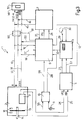
- Number 1 in Fig.1 indicates an absolute position transducer (encoder) comprising an incremental encoder 2 to which is connected a sensor circuit 3 connected to the input of a detecting circuit 4.
- the output of detecting circuit 4 is connected to a rotation count block 5 interacting, as described later, with a control circuit 6 connected to a coding circuit 7.
- a supply circuit 10, connected in customary manner (not shown) to the various blocks of encoder 1, is connected to an external supply mains 55, and presents a buffer battery 11 for ensuring supply to parts of encoder 1, in particular rotation count block 5, even in the event of a power failure.
- circuit 10 also provides for controlling supply, and is connected by lines 56 and 28 to control circuit 6.
- Incremental encoder 2 which is a substantially known type, presents a coded disk 13 connected integral with a shaft 15 the angular position of which requires precision measurement, and is connected in customary manner to optoelectronic means 14 for emitting three output signals over respective lines 16, 17 and 18 indicated respectively A, B and Zero.
- the signals along lines 16 and 17 consist of two sequences of pulses (normally square waves) with a 90° phase lead or delay depending on the direction of rotation of shaft 15. Each pulse is equal to an elementary angular increment of shaft 15.
- the signal along line 18 indicates 360° rotation of shaft 15, and consists of a sequence of pulses, hereinafter referred to as "zero pulses", each emitted for each complete turn of shaft 15.
- Line 18 is connected to control block 6, which presents an output line 20 connected, together with lines 16 and 17, to the input of a decoding circuit 50 described in detail later on.
- Disk 13 is also connected to sensor 3, which emits an output pulse for each turn of shaft 15 over lines 24 and 25 indicated respectively A1 and B1.
- the pulses on lines 24 and 25 are slightly out of phase, for indicating the direction of rotation of shaft 15.
- sensor 3 is constantly enabled by circuit 10 and must therefore absorb very little current.
- Sensor 3 may conveniently consist, for example, of a Hall-effect sensor, a magnetic switch (REED), or a capacitive sensor.
- Lines 24 and 25 are connected to circuit 4, which provides for amplifying and clipping the signals generated by sensor 3.
- Circuit 4 also processes the signals on lines 24 and 25, and supplies rotation count block 5 (comprising a counter) with a series of directional count pulses relative to rotation of disc 13 over lines 27 and 57 respectively transmitting said pulses and the count direction (UP/DOWN).
- Circuit 4 is also connected to control circuit 6 by an alarm line 12.
- Rotation count block 5 presents a memory 29 in which the pulse count from line 27 is recorded, and which thus provides for storing the number (corresponding to a position) of complete turns of shaft 15. The data stored in memory 29 is preserved even in the event of a power cut, in which case, memory 29 is conveniently supplied by battery 11 connected to block 10. Rotation count block 5 also presents a key 30 for resetting memory 29 when calibrating encoder 1. The content of memory 29 is supplied to control circuit 6 over line 32, for the purpose described in detail later on.
- control circuit 6 The output of control circuit 6 is connected over lines 34 and 35 to coding circuit 7, which supplies control circuit 6 with a coded (MATCH) signal over line 37.
- MATCH coded
- shaft 15 of incremental encoder 2 is normally connected via a drive (not shown) to an element (axis) normally sliding along a machine slideway and the position of which is determined via a rotation count of shaft 15.
- the axis is set to a zero start position from which the number of turns of shaft 15 is to be counted, and in which memory 29 of rotation count block 5 is reset by key 30.
- rotation count block 5 counts the pulses supplied by detecting block 4 over lines 27 and 57, according to the direction of rotation of shaft 15, and updates the content of memory 29.
- Memory 29 therefore contains at all times a value indicating the number of turns effected by shaft 15 as of the zero position, which information is preserved even in the event of supply being cut off to the machine to which encoder 1 is connected.
- the information contained in memory 29 is transmitted to decoding circuit 50 over lines 20, 16 and 17, with no initial reset procedure required.
- the axis is moved until the first zero pulse over line 18 enables controller circuit 6 and provides for automatically requalifying the axis position.
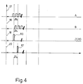
- controller circuit 6 when the machine is turned on, thus enabling control circuit 6 over line 56, and a zero pulse (60) is received by controller circuit 6 over line 18, controller circuit 6, over line 32, provides for reading the value contained in memory 29 and indicating the number of turns effected by shaft 15 as of the zero start position.
- This value is sent by control circuit 6 to coding circuit 7, which emits a second so-called "dummy zero" pulse (61) separated from the real zero pulse by a time interval TO during which (n) pulses equal to the number (n) stored in memory 29, and equal to 1 in the Fig.4 example, are transmitted over line 16 or 17.
- the information stored in memory 29 is thus transmitted to decoding circuit 50 using the normal pulses over lines 16 and 17, with no additional data line required.
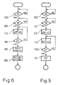
- Control circuit 6 operates as shown in the Fig.5 block diagram. This presents a start block 100, which determines whether power has been supplied to the whole of encoder 1. If it has not, control circuit 6 performs a wait cycle. If it has, this is detected by a signal over line 56.
- Block 100 then goes on to wait block 110, which waits for and recognizes a zero pulse over line 18.
- block 110 goes on to block 115, which provides for reading the content (n) of memory 29 and supplying it to coding circuit 7 over line 34.
- Block 115 then goes on to block 120, which provides for detecting the pulses over line 16 or 17 and supplying them to circuit 7 over line 35.
- circuit 7 When the (n)th pulse over line 35 is found by circuit 7 to match the number stored in memory 29 and supplied to circuit 7 over line 34, circuit 7 supplies a MATCH signal over line 37 to block 6. Said MATCH signal is detected by block 130, which therefore goes straight to block 131 for emitting an end-of-transmission (dummy zero) signal, which is sent by control circuit 6 on to line 20 and also provides for disabling circuit 6.
- Decoding circuit 50 provides for an exact interpretation of the real zero and dummy zero pulses.
- Fig.6 shows an operating logic block diagram of decoding circuit 50.
- This presents a start block 150, which waits for a signal indicating that encoder 1 has been turned on. When this occurs, block 150 goes on to block 160, which waits for a zero signal over line 18. When this is detected, block 160 goes on to block 170, which enables counter 51 for counting the pulses supplied by incremental encoder 2 over line 16 or 17. Block 170 then goes on to block 180, which determines whether a zero pulse is supplied over line 18 subsequent to that detected by block 160.
- block 185 goes on to block 190 which, as of value Ntot, provides for enabling operation of encoder 1 in the same way as a normal incremental encoder, whereby the signals supplied by incremental encoder 2 over lines 16, 17 and 18 are supplied to decoding circuit 50, which operates in conventional manner as regards the conventional downstream circuits to which it is connected.
- Absolute encoder 1 also presents means for detecting faults which may impair position measuring accuracy.
- detecting block 4 comprises a circuit for detecting error conditions (e.g. absence of either input signal, illegal transitions, etc.) and supplying control circuit 6 with an error signal over line 12.
- Control circuit 6 in turn supplies a special signal over line 20, which is identified by decoding circuit 50 which accordingly informs the operator.
- Supply circuit 10 also comprises a detecting circuit for checking the charge of battery 11. When this falls below a predetermined threshold value, circuit 10 supplies an error signal over line 28 to control circuit 6, which supplies a special signal over line 20. This is identified by decoding circuit 50 which accordingly informs the operator.
- Fig.2 shows a variation of the Fig.1 arrangement, in which the component parts of encoder 1 similar to those of Fig.1 are indicated using the same numbering system.
- the Fig.2 arrangement differs as regards connection of control circuit 6 and coding circuit 7, connection of the zero pulse transmission line, and operation of circuits 6 and 7.
- the output of circuit 6 is connected to the input of coding circuit 7 over line 40, and an output of circuit 7 is connected to an input of control circuit 6 over line 41.
- the count pulses for decoding circuit 50 are transmitted by coding circuit 7 over line 43, while the dummy zero pulse is transmitted over line 20 between control circuit 6 and line 18.
- lines 16 and 17 are no longer connected to control circuit 6.
- the information stored in memory 29 is transmitted to decoding circuit 50 over lines 43, 16 and 17, with no initial reset procedure required.
- the axis is moved until the first zero pulse over line 18 enables control circuit 6 and provides for automatically requalifying the axis position.
- control circuit 6 When the machine is turned on and a zero pulse supplied to control circuit 6, this provides for reading the value stored in memory 29 and indicating the number of turns effected by shaft 15 as of the initial zero position.
- the count value in memory 29 is supplied by control circuit 6 over line 40 to coding circuit 7 which, following the zero pulse, supplies a sequence of pulses equal to the number stored in memory 29, or a coded sequence expressing the number stored in memory 29.
- the information stored in memory 29 is thus transmitted over line 43 to decoding circuit 50 using the same line 18 used for transmitting the zero pulse, with no additional data line required.
- Control circuit 6 operates as shown in the Fig.7 block diagram. This presents a start block 200, which determines whether power has been supplied to the whole of encoder 1. If it has not, circuit 6 performs a wait cycle. If it has, this is detected by a signal over line 56. Block 200 goes on to wait block 210, which waits for and recognizes a zero pulse over line 18. When the first zero pulse is received by circuit 6, block 210 goes on to block 215, which provides for reading the content (n) of memory 29 and supplying it to coding circuit 7 over line 40. Circuit 7 supplies on to line 18, over line 43, a number of pulses equal to that (n) read in memory 29, after which, it supplies circuit 6 over line 41 with a signal detected via block 219. Block 219 then goes on to block 220, which emits an end-of-transmission (dummy zero) signal, which is sent by control circuit 6 on to line 20 and also provides for disabling circuit 6.
- start block 200 determines whether power has been supplied to the whole of encoder 1. If it has not, circuit
- Decoding circuit 50 provides for an exact interpretation of the real zero and dummy zero pulses.
- Fig.8 shows an operating logic block diagram of decoding circuit 50.
- This presents a start block 250, which waits for a signal indicating that encoder 1 has been turned on.
- block 250 goes on to block 260, which waits for a zero signal over line 18.
- block 260 goes on to block 270, which enables counter 51 for counting the (n) pulses transmitted over line 18 by circuit 7, and also provides, via counter 52, for counting the (n1) pulses transmitted over line 16 or 17 during transmission of said (n) pulses following the zero pulse.
- Block 270 then goes on to block 280, which determines whether the dummy zero pulse is supplied to line 18 by circuit 6 over line 20.
- block 285 goes on to block 286 which, as of value Ntot, provides for enabling operation of encoder 1 in the same way as a normal incremental encoder, whereby the signals supplied by incremental encoder 2 over lines 16, 17 and 18 are supplied to decoding circuit 50, which operates in conventional manner as regards the conventional downstream circuits to which it is connected.
- Fig.3 shows a second variation of the Fig.1 arrangement, in which the component parts of encoder 1 similar to those in Fig.1 are indicated using the same numbering system.
- Fig.3 arrangement differs as regards connection of coding circuit 7 and decoding circuit 50, and operation of coding circuit 7 and control circuit 6. Also, lines 16 and 17 of incremental encoder 2 present an electronic switch block 90 controlled by output signal 91 from control circuit 6.
- lines 16, 17 and 18 of incremental encoder 2 present respective branch lines 16′, 17′ and 18′ to control circuit 6, and two lines 45 and 46 from coding circuit 7 are connected respectively to lines 16 and 17 downstream from block 90.
- the information in memory 29 is transmitted to decoding circuit 50 over lines 16 and 17, with no initial reset procedure required.
- the axis is moved until the first zero pulse over line 18 enables control circuit 6 and provides for automatically requalifying the axis position.
- control circuit 6 When the total number of pulses Ntot has been transmitted, control circuit 6 emits an end-of-transmission signal over line 20, and reconnects lines 16 and 17 to decoding circuit 50 via signal 91 to block 90, so that, at the end of this phase, control circuit 6 is disabled and encoder 2 operates in the same way as a normal incremental encoder, as described in connection with Fig.1.
- Control circuit 6 operates as shown in the Fig.9 block diagram. This presents a start block 300, which determines whether power has been supplied to the whole of encoder 1. If it has not, circuit 6 performs a wait cycle. If it has, this is detected by a signal over line 56. Block 300 goes on to wait block 310, which waits for and recognizes a zero pulse over line 18. When the first zero pulse is received by circuit 6, block 310 goes on to block 311, which disconnects block 90 via signal 91 and goes on to block 315, which provides for reading the content (n) of memory 29 and supplying it to coding circuit 7 over line 34.
- Circuit 7 sends on to line 16 or 17, via lines 45 and 46, a train of pulses (k) equal to the number (n) in memory 29 multiplied by the number of pulses N emitted in one complete turn by encoder 2. Said pulse train is conveniently emitted at a much higher frequency than the pulses generated by incremental encoder 2 and transmitted on to lines 16 and 17.
- Block 315 goes on to block 316 which, while said pulse train is being emitted by circuit 7, supplies circuit 7 over line 35 with the number of pulses (K1) produced by encoder 2 on line 16 or 17.
- Fig.10 shows an operating logic block diagram of decoding circuit 50.
- This presents a start block 350, which waits for a signal indicating that encoder 1 has been turned on.
- block 350 goes on to block 360, which waits for a zero signal over line 18.
- block 360 goes on to block 370, which enables counter 51 for counting on line 16 or 17 the (n*N + K1) pulses following the zero pulse and transmitted at high frequency over lines 45 and 46.
- Block 370 then goes on to block 380, which determines whether the dummy zero pulse is supplied to line 18 by circuit 6 over line 20.
- block 380 goes on to block 400, which stops counter 51 and, as of count value Ntot, provides for enabling operation of encoder 1 in the same way as a normal incremental encoder, whereby the signals supplied by incremental encoder 2 over lines 16, 17 and 18 are supplied to decoding circuit 50, which operates in conventional manner as regards the conventional downstream circuits to which it is connected.
- the electronic circuits added to incremental encoder 2 therefore comprise low-consumption, permanent detecting branch blocks 3, 4 and 5, and blocks 6 and 7 which provide exclusively for transmitting position data at the initial repositioning stage, subsequent to which, absolute encoder 1 operates in exactly the same way as a normal incremental encoder. Consequently, absolute encoder 1 is connected to decoding circuit 50 over the same line as an incremental encoder.
- the present invention therefore provides for an absolute encoder of relatively straightforward design and little extra cost as compared with an incremental encoder, and which may be applied relatively easily to existing incremental encoders.
- control circuit 6 and coding circuit 7, may be combined into one circuit.
- sensor circuit 3 and detecting circuit 4 may be combined into one circuit having the same characteristics as both when employed separately.
- detecting circuit 4 may even be dispensed with.
Claims (16)
- Positionsgeber (1), der einen Schrittgeber (2) aufweist, der eine fest mit einer drehbaren Welle (15) verbundene Codescheibe (13) hat; wobei der Schrittgeber (2) wenigstens drei Ausgangssignale liefert: ein erstes Signal, das aus einer Impulsfolge besteht, die gleich einem elementaren Winkelschritt der Welle (15) ist; ein zweites Signal, das dem ersten Signal gleicht und in bezug darauf phasenverschoben ist, um Information relativ zu der Drehrichtung der Welle (15) zu übertragen; und ein drittes Signal, das aus einer Folge von Nullimpulsen besteht, die jeweils für jede 360°-Umdrehung der Scheibe (13) abgegeben werden; wobei das erste, das zweite und das dritte Signal jeweils auf einer entsprechenden ersten, zweiten und dritten Leitung übertragen werden; gekennzeichnet durch die Tatsache, daß der Positionsgeber aufweist: eine Sensoreinrichtung (3), die mit dem Schrittgeber (2) verbunden ist, um ein viertes Signal bei jeder vollständigen Umdrehung der Codescheibe (13) abzugeben; eine rücksetzbare Zählereinrichtung (5), um das von der Sensorreinrichtung (3) abgegebene vierte Signal zu zählen und die Zahl der Umdrehungen der Scheibe (13) in einem Permanentspeicher (29) zu speichern; und eine erste elektronische Einrichtung (6), die von dem ersten der von dem Schrittgeber (2) erzeugten Nullimpulse freigegeben wird, wobei die erste elektronische Einrichtung (6) mit einer zweiten elektronischen Einrichtung (7) zusammenwirkt, um die in dem Speicher (29) enthaltene Information in bezug auf die Zahl der Umdrehungen codiert zu einer Einrichtung (50) zum Empfangen der Positionsinformation des Positionsgebers (1) zu übertragen.
- Positionsgeber nach Anspruch 1, gekennzeichnet durch die Tatsache, daß die erste elektronische Einrichtung Mittel (100, 110; 200, 210; 300, 310) aufweist, um anschließend an das Einschalten des positionsgebers (1) den ersten Nullimpuls zu detektieren, der von dem Schrittgeber (2) abgegeben wird.
- Positionsgeber nach Anspruch 1 oder 2, gekennzeichnet durch die Tatsache, daß die erste oder zweite elektronische Einrichtung (6, 7) Mittel (131; 220; 320) aufweist, um anschließend an die Übertragung der Information in bezug auf die in dem Speicher (29) gespeicherte Zahl zu der Empfangseinrichtung (50) einen codierten Pseudo-Nullimpuls zu erzeugen.
- Positionsgeber nach Anspruch 3, gekennzeichnet durch die Tatsache, daß der Pseudo-Nullimpuls auf der gleichen Leitung (20) wie der Nullimpuls übertragen wird.
- Positionsgeber nach einem der vorhergehenden Ansprüche 2-4, gekennzeichnet durch die Tatsache, daß die erste oder die zweite Einrichtung (6, 7) Mittel (131; 220; 320) aufweist, durch die sie anschließend an die Abgabe des Pseudo-Nullimpulses gesperrt wird.
- Positionsgeber nach einem der vorhergehenden Ansprüche, gekennzeichnet durch die Tatsache, daß die erste oder die zweite elektronische Einrichtung (6, 7) Mittel (116, 120, 130, 131) aufweist, um den codierten Pseudo-Nullimpuls auf solche Weise zu übertragen, daß der Nullimpuls und der Pseudo-Nullimpuls durch ein Zeitintervall TO voneinander getrennt sind, in dem eine Zahl von Impulsen gleich der in dem Speicher (29) der Zählereinrichtung (5) gespeicherten Zahl auf der ersten (16) oder der zweiten (17) Leitung übertragen wird.
- Positionsgeber nach einem der vorhergehenden Ansprüche 1-5, gekennzeichnet durch die Tatsache, daß die erste oder die zweite elektronische Einrichtung (6, 7) Mittel (215, 219) aufweist, um auf der dritten Leitung (18) anschließend an den Nullimpuls eine codierte Impulssequenz, die die in dem Speicher (29) gespeicherte Zahl ausdrückt, abzugeben.
- Positionsgeber nach einem der vorhergehenden Ansprüche 1-5, gekennzeichnet durch die Tatsache, daß die erste oder die zweite elektronische Einrichtung (6, 7) Mittel (315, 316, 317) aufweist, um die in dem Speicher (29) gespeicherte Zahl mit der Zahl von Impulsen pro Umdrehung (N), die von dem Schrittgeber (2) geliefert wird, zu multiplizieren, um eine zweite Zahl (K) zu ergeben; wobei die elektronische Einrichtung (7) eine Impulsfolge gleich der zweiten Zahl (K) plus der Zahl von Impulsen (K1), die von dem Schrittgeber (2) während der Übertragung der Impulsfolge auf der ersten oder der zweiten Leitung erzeugt werden, erzeugt; wobei die Impulsfolge auf der ersten (16) oder der zweiten (17) Leitung übertragen wird.
- Positionsgeber nach Anspruch 8, gekennzeichnet durch die Tatsache, daß die Impulsfolge mit einer Geschwindigkeit übertragen wird, die viel größer als die mittlere Geschwindigkeit ist, mit der die Impulse auf der ersten (16) und der zweiten (17) Leitung übertragen werden.
- Positionsgeber nach einem der vorhergehenden Ansprüche, gekennzeichnet durch die Tatsache, daß die Einrichtung (50) zum Empfang der Positionsinformation aufweist: Mittel (150, 160; 250, 260; 350, 360) zum Detektieren des ersten Nullimpulses, der nach dem Einschalten von dem Schrittgeber (2) erzeugt wird; Mittel (170, 180, 185; 270, 280, 285; 370, 380) zum Zählen und Verarbeiten der Information relativ zu der in dem Speicher (29) gespeicherten und von der ersten oder der zweiten elektronischen Einrichtung (6, 7) übertragenen Zahl; Mittel (180; 280; 380) zum Detektieren des Pseudo-Nullimpulses; und Mittel (190; 286; 400) zum fortgesetzten Empfangen von Informationen von dem Schrittgeber (2) auf der ersten, der zweiten und der dritten Leitung (16, 17, 18).
- Positionsgeber nach einem der vorhergehenden Ansprüche, gekennzeichnet durch die Tatsache, daß die Sensoreinrichtung einen Halleffekt-Sensor aufweist.
- Positionsgeber nach einem der vorhergehenden Ansprüche 1-10, gekennzeichnet durch die Tatsache, daß die Sensoreinrichtung einen Magnetschalter (REED) aufweist.
- Positionsgeber nach einem der vorhergehenden Ansprüche, gekennzeichnet durch die Tatsache, daß eine Detektierschaltung (4) zwischen der Sensoreinrichtung (3) und der Zählereinrichtung (5) vorgesehen ist; wobei die Detektierschaltung (4) das Signal von der Sensoreinrichtung (3) verstärkt und begrenzt.
- Positionsgeber nach Anspruch 13, gekennzeichnet durch die Tatsache, daß er eine Schaltung aufweist, um Fehlerzustände in den von der Sensoreinrichtung (3) zu der Detektierschaltung (4) gelieferten Signalen zu detektieren; wobei die Schaltung (4) ausgebildet ist, um der ersten elektronischen Einrichtung (6) ein Fehlersignal zuzuführen.
- Positionsgeber nach einem der vorhergehenden Ansprüche, gekennzeichnet durch die Tatsache, daß der Absolutwertgeber (1) von einer Überwachungs- und Versorgungsschaltung (10) gespeist wird, die mit einem externen Netzanschluß (55) verbunden ist und eine Pufferbatterie (11) aufweist, um die Stromzufuhr zu Teilen des Absolutwertgebers (1) auch bei einem Stromausfall sicherzustellen.
- Positionsgeber nach Anspruch 15, gekennzeichnet durch die Tatsache, daß die Überwachungs- und Versorgungsschaltung (10) den Ladezustand der Batterie (11) feststellt und ein Fehlersignal abgibt, wenn der Ladezustand einen vorbestimmten Grenzwert unterschreitet.
Applications Claiming Priority (2)
| Application Number | Priority Date | Filing Date | Title |
|---|---|---|---|
| IT6719490 | 1990-03-16 | ||
| IT67194A IT1240133B (it) | 1990-03-16 | 1990-03-16 | Dispositivo trasduttore di posizione |
Publications (2)
| Publication Number | Publication Date |
|---|---|
| EP0449037A1 EP0449037A1 (de) | 1991-10-02 |
| EP0449037B1 true EP0449037B1 (de) | 1994-08-03 |
Family
ID=11300382
Family Applications (1)
| Application Number | Title | Priority Date | Filing Date |
|---|---|---|---|
| EP91103848A Expired - Lifetime EP0449037B1 (de) | 1990-03-16 | 1991-03-13 | Positionsgeber |
Country Status (4)
| Country | Link |
|---|---|
| US (1) | US5233355A (de) |
| EP (1) | EP0449037B1 (de) |
| DE (1) | DE69103183D1 (de) |
| IT (1) | IT1240133B (de) |
Families Citing this family (15)
| Publication number | Priority date | Publication date | Assignee | Title |
|---|---|---|---|---|
| EP0502534B1 (de) * | 1991-03-06 | 1997-12-17 | Hitachi, Ltd. | Kodierer |
| AT404300B (de) * | 1992-02-20 | 1998-10-27 | Rsf Elektronik Gmbh | Drehgeber |
| DE4407474C2 (de) * | 1994-03-07 | 2000-07-13 | Asm Automation Sensorik Messte | Drehwinkelsensor |
| US5880681A (en) * | 1997-09-16 | 1999-03-09 | Caterpillar Inc. | Apparatus for determining the position of a work implement |
| US6272625B1 (en) | 1997-10-08 | 2001-08-07 | Oak Technology, Inc. | Apparatus and method for processing events in a digital versatile disc (DVD) system using system threads and separate dormant/awake counter threads and clock driven semaphores |
| US6556005B1 (en) | 2000-01-27 | 2003-04-29 | Goodrich Avionics Systems, Inc. | Magnetic encoder apparatus capable of resolving axial and rotational displacements |
| DE10125604A1 (de) * | 2001-05-25 | 2002-12-05 | Siemens Ag | Verfahren und Schaltungsanordnung zur Auswertung von Impulsfolgen, die ein Messsignal für physikalische Größen darstellen |
| DE10130307C2 (de) * | 2001-06-22 | 2003-08-21 | Siemens Ag | Verfahren und Schaltungsanordnung zur Auswertung von Sensorausgangssignalen |
| DE10308683B3 (de) * | 2003-02-28 | 2004-04-08 | Stegmann Gmbh & Co. Kg | Multiturn-Drehgeber |
| JP4481137B2 (ja) * | 2003-11-13 | 2010-06-16 | アスモ株式会社 | モータ、回転制御装置、及び回転検出回路 |
| US7278375B2 (en) * | 2005-04-11 | 2007-10-09 | Brian Charles Ross | Animal deterrent apparatus for mounting to a culvert |
| DE102008049140A1 (de) | 2008-09-26 | 2010-04-01 | Dr. Johannes Heidenhain Gmbh | Anordnung und Verfahren zur Erzeugung eines Referenzimpulses für ein Positionsmessgerät |
| US9310195B2 (en) | 2010-08-24 | 2016-04-12 | Rotork Controls Limited | Apparatus adapted to provide an indication of an angular position of an input member over multiple turns |
| CN103048012B (zh) * | 2012-08-10 | 2015-01-28 | 深圳市正弦电气股份有限公司 | 一种正余弦编码器的零点校正方法、系统及电梯 |
| US11156491B2 (en) * | 2019-01-17 | 2021-10-26 | Te Connectivity Corporation | Inductive sensor assembly for fluid measurements |
Family Cites Families (10)
| Publication number | Priority date | Publication date | Assignee | Title |
|---|---|---|---|---|
| US4014015A (en) * | 1975-05-05 | 1977-03-22 | Devtron Corporation | Absolute digital position measurement system |
| JPS54163061A (en) * | 1978-06-15 | 1979-12-25 | Nippon Denso Co | Revolution positional detector |
| DE2948854A1 (de) * | 1979-12-05 | 1981-06-11 | Dr. Johannes Heidenhain Gmbh, 8225 Traunreut | Inkrementales messsystem |
| DE3231990A1 (de) * | 1982-08-27 | 1984-03-01 | Siemens AG, 1000 Berlin und 8000 München | Auswerteeinrichtung fuer einen digitalen inkrementalgeber |
| US4608714A (en) * | 1982-09-03 | 1986-08-26 | Gte Valeron Corporation | Low battery detector for a machine system using infrared telemetry |
| DE3310348A1 (de) * | 1983-03-22 | 1984-09-27 | Siemens AG, 1000 Berlin und 8000 München | Inkrementale wegmesseinrichtung |
| JPH0658223B2 (ja) * | 1985-06-13 | 1994-08-03 | 株式会社ゼクセル | 回転装置用タイミング信号発生装置 |
| JPH01116409A (ja) * | 1987-10-29 | 1989-05-09 | Fanuc Ltd | アブソリュート・ロータリ・エンコーダ |
| US4942394A (en) * | 1987-12-21 | 1990-07-17 | Pitney Bowes Inc. | Hall effect encoder apparatus |
| US4855734A (en) * | 1988-03-29 | 1989-08-08 | International Machine & Tool Corporation | Relative position indication system |
-
1990
- 1990-03-16 IT IT67194A patent/IT1240133B/it active IP Right Grant
-
1991
- 1991-03-13 DE DE69103183T patent/DE69103183D1/de not_active Expired - Lifetime
- 1991-03-13 EP EP91103848A patent/EP0449037B1/de not_active Expired - Lifetime
- 1991-03-15 US US07/669,759 patent/US5233355A/en not_active Expired - Fee Related
Also Published As
| Publication number | Publication date |
|---|---|
| DE69103183D1 (de) | 1994-09-08 |
| EP0449037A1 (de) | 1991-10-02 |
| IT9067194A1 (it) | 1991-09-16 |
| IT1240133B (it) | 1993-11-27 |
| US5233355A (en) | 1993-08-03 |
| IT9067194A0 (it) | 1990-03-16 |
Similar Documents
| Publication | Publication Date | Title |
|---|---|---|
| EP0449037B1 (de) | Positionsgeber | |
| EP0331828B1 (de) | Absoluter Kodierer des Multiumlaufstyps | |
| US4628609A (en) | Incremental measuring and machine control system | |
| WO1988009026A1 (en) | Improvements relating to rotary encoders | |
| NO842324L (no) | Automatisk, dynamisk feilkompensator | |
| US9614663B2 (en) | Method and device for serial data transmission over a bidirectional data channel | |
| US4855734A (en) | Relative position indication system | |
| JP7041002B2 (ja) | 位置エンコーダサンプリングタイミングシステム | |
| US5734173A (en) | Method and device for positioning of moving machinery parts | |
| US4952874A (en) | Position-reading system with switchable reading units for machine-tool parts rotatable through 360 | |
| EP0105086B1 (de) | Schnittstellensystem für Positionsabtastwandler | |
| CN105702016B (zh) | 用于校验位置测量装置的工作时钟信号的装置和方法 | |
| DE19920393B4 (de) | Anordnung zum Bestimmen eines Volumens eines Gasstroms | |
| JP7092535B2 (ja) | エンコーダ及びエンコーダを作動させるための方法 | |
| US20040119000A1 (en) | Method for operating a position measuring device and position measuring device suitable therefor | |
| CN110940359B (zh) | 编码器和控制系统 | |
| JPH06258099A (ja) | 多回転アブソリュートエンコーダ | |
| EP0080531B1 (de) | Positionsgeber | |
| US6345520B1 (en) | Device for transferring digital data between a rotating part and a fixed part of a machine, particularly for hosiery knitting machines and the like | |
| CN110941208B (zh) | 编码器和控制系统 | |
| JP4144522B2 (ja) | インクリメンタルリニアスケールの位置情報通信データフレーム構成方法 | |
| US5191271A (en) | Process and device for adjusting an axis | |
| JPS63289417A (ja) | パルス・エンコ−ダ | |
| JPS62163108A (ja) | 数値制御装置の原点復帰方式 | |
| EP1163530A1 (de) | Verwischte geschwindigkeitsabschätzung |
Legal Events
| Date | Code | Title | Description |
|---|---|---|---|
| PUAI | Public reference made under article 153(3) epc to a published international application that has entered the european phase |
Free format text: ORIGINAL CODE: 0009012 |
|
| AK | Designated contracting states |
Kind code of ref document: A1 Designated state(s): DE ES FR GB |
|
| 17P | Request for examination filed |
Effective date: 19920323 |
|
| 17Q | First examination report despatched |
Effective date: 19930505 |
|
| GRAA | (expected) grant |
Free format text: ORIGINAL CODE: 0009210 |
|
| AK | Designated contracting states |
Kind code of ref document: B1 Designated state(s): DE ES FR GB |
|
| PG25 | Lapsed in a contracting state [announced via postgrant information from national office to epo] |
Ref country code: FR Effective date: 19940803 Ref country code: ES Free format text: THE PATENT HAS BEEN ANNULLED BY A DECISION OF A NATIONAL AUTHORITY Effective date: 19940803 |
|
| REF | Corresponds to: |
Ref document number: 69103183 Country of ref document: DE Date of ref document: 19940908 |
|
| PG25 | Lapsed in a contracting state [announced via postgrant information from national office to epo] |
Ref country code: DE Effective date: 19941104 |
|
| EN | Fr: translation not filed | ||
| PG25 | Lapsed in a contracting state [announced via postgrant information from national office to epo] |
Ref country code: GB Effective date: 19950313 |
|
| PLBE | No opposition filed within time limit |
Free format text: ORIGINAL CODE: 0009261 |
|
| STAA | Information on the status of an ep patent application or granted ep patent |
Free format text: STATUS: NO OPPOSITION FILED WITHIN TIME LIMIT |
|
| 26N | No opposition filed | ||
| GBPC | Gb: european patent ceased through non-payment of renewal fee |
Effective date: 19950313 |