EP0447985A1 - Verdrängungspumpe - Google Patents
Verdrängungspumpe Download PDFInfo
- Publication number
- EP0447985A1 EP0447985A1 EP91104039A EP91104039A EP0447985A1 EP 0447985 A1 EP0447985 A1 EP 0447985A1 EP 91104039 A EP91104039 A EP 91104039A EP 91104039 A EP91104039 A EP 91104039A EP 0447985 A1 EP0447985 A1 EP 0447985A1
- Authority
- EP
- European Patent Office
- Prior art keywords
- cracking
- fluid
- pump
- valve member
- valve
- Prior art date
- Legal status (The legal status is an assumption and is not a legal conclusion. Google has not performed a legal analysis and makes no representation as to the accuracy of the status listed.)
- Ceased
Links
- 238000006073 displacement reaction Methods 0.000 title claims abstract description 13
- 239000012530 fluid Substances 0.000 claims abstract description 130
- 238000005336 cracking Methods 0.000 claims abstract description 118
- 239000007788 liquid Substances 0.000 claims abstract description 25
- 230000003287 optical effect Effects 0.000 claims abstract description 8
- 230000004044 response Effects 0.000 claims abstract description 7
- 230000005355 Hall effect Effects 0.000 claims description 2
- 238000005086 pumping Methods 0.000 abstract description 53
- 239000002184 metal Substances 0.000 description 13
- 230000006870 function Effects 0.000 description 9
- 229940079593 drug Drugs 0.000 description 8
- 239000003814 drug Substances 0.000 description 8
- 230000006835 compression Effects 0.000 description 7
- 238000007906 compression Methods 0.000 description 7
- CWYNVVGOOAEACU-UHFFFAOYSA-N Fe2+ Chemical compound [Fe+2] CWYNVVGOOAEACU-UHFFFAOYSA-N 0.000 description 6
- 238000001802 infusion Methods 0.000 description 6
- 238000012544 monitoring process Methods 0.000 description 6
- 238000010586 diagram Methods 0.000 description 4
- 239000004800 polyvinyl chloride Substances 0.000 description 4
- 206010001526 Air embolism Diseases 0.000 description 3
- 239000003990 capacitor Substances 0.000 description 3
- 230000007246 mechanism Effects 0.000 description 3
- 229920000915 polyvinyl chloride Polymers 0.000 description 3
- 230000008878 coupling Effects 0.000 description 2
- 238000010168 coupling process Methods 0.000 description 2
- 238000005859 coupling reaction Methods 0.000 description 2
- 238000001514 detection method Methods 0.000 description 2
- 230000004048 modification Effects 0.000 description 2
- 238000012986 modification Methods 0.000 description 2
- 238000000429 assembly Methods 0.000 description 1
- 230000000712 assembly Effects 0.000 description 1
- 230000008859 change Effects 0.000 description 1
- 238000010276 construction Methods 0.000 description 1
- 230000000694 effects Effects 0.000 description 1
- 230000000670 limiting effect Effects 0.000 description 1
- 238000004519 manufacturing process Methods 0.000 description 1
- 239000002991 molded plastic Substances 0.000 description 1
- 230000002572 peristaltic effect Effects 0.000 description 1
- 238000002407 reforming Methods 0.000 description 1
- 238000005096 rolling process Methods 0.000 description 1
- 238000007493 shaping process Methods 0.000 description 1
- 238000009966 trimming Methods 0.000 description 1
- 238000011144 upstream manufacturing Methods 0.000 description 1
- 230000000007 visual effect Effects 0.000 description 1
Images


Classifications
-
- A—HUMAN NECESSITIES
- A61—MEDICAL OR VETERINARY SCIENCE; HYGIENE
- A61M—DEVICES FOR INTRODUCING MEDIA INTO, OR ONTO, THE BODY; DEVICES FOR TRANSDUCING BODY MEDIA OR FOR TAKING MEDIA FROM THE BODY; DEVICES FOR PRODUCING OR ENDING SLEEP OR STUPOR
- A61M5/00—Devices for bringing media into the body in a subcutaneous, intra-vascular or intramuscular way; Accessories therefor, e.g. filling or cleaning devices, arm-rests
- A61M5/14—Infusion devices, e.g. infusing by gravity; Blood infusion; Accessories therefor
- A61M5/142—Pressure infusion, e.g. using pumps
- A61M5/14212—Pumping with an aspiration and an expulsion action
- A61M5/14228—Pumping with an aspiration and an expulsion action with linear peristaltic action, i.e. comprising at least three pressurising members or a helical member
-
- A—HUMAN NECESSITIES
- A61—MEDICAL OR VETERINARY SCIENCE; HYGIENE
- A61M—DEVICES FOR INTRODUCING MEDIA INTO, OR ONTO, THE BODY; DEVICES FOR TRANSDUCING BODY MEDIA OR FOR TAKING MEDIA FROM THE BODY; DEVICES FOR PRODUCING OR ENDING SLEEP OR STUPOR
- A61M5/00—Devices for bringing media into the body in a subcutaneous, intra-vascular or intramuscular way; Accessories therefor, e.g. filling or cleaning devices, arm-rests
- A61M5/14—Infusion devices, e.g. infusing by gravity; Blood infusion; Accessories therefor
- A61M5/168—Means for controlling media flow to the body or for metering media to the body, e.g. drip meters, counters ; Monitoring media flow to the body
- A61M5/16831—Monitoring, detecting, signalling or eliminating infusion flow anomalies
- A61M5/16854—Monitoring, detecting, signalling or eliminating infusion flow anomalies by monitoring line pressure
-
- A—HUMAN NECESSITIES
- A61—MEDICAL OR VETERINARY SCIENCE; HYGIENE
- A61M—DEVICES FOR INTRODUCING MEDIA INTO, OR ONTO, THE BODY; DEVICES FOR TRANSDUCING BODY MEDIA OR FOR TAKING MEDIA FROM THE BODY; DEVICES FOR PRODUCING OR ENDING SLEEP OR STUPOR
- A61M39/00—Tubes, tube connectors, tube couplings, valves, access sites or the like, specially adapted for medical use
- A61M39/22—Valves or arrangement of valves
- A61M39/28—Clamping means for squeezing flexible tubes, e.g. roller clamps
- A61M39/281—Automatic tube cut-off devices, e.g. squeezing tube on detection of air
Definitions
- This invention generally pertains to a sensor for monitoring the operation of a pump, and more specifically, to apparatus for monitoring a fluid flow condition related to the operation of a positive displacement pump.
- Blockage of fluid flow from the pump is detected when the pressure at the pump output port increases to a level that exceeds a predetermined threshold.
- some pumps use drip detectors installed in the supply line immediately upstream of the pump inlet.
- connection of the drip detector adds to the time required to set up a drug infusion system, requires additional hardware, and makes the system more complex to use.
- Some infusion pumps include an air-in-line sensor that detects air bubbles larger than a specified size, e.g. larger than 100 microliters, since such bubbles can produce an air embolism in the patient's circulatory system that may be harmful.
- Air-in-line detectors typically monitor the fluid output of the pump using a matched resonant frequency ultrasonic piezoelectric transmitter and receiver that are disposed on opposite sides of a fluid passage in the pump. The ultrasonic piezoelectric transmitter applies an ultrasonic signal to one side of the fluid passage and the receiver monitors the level of that signal on the other side of the passage.
- a pump control circuit responds to the reduced output signal level caused by a large air bubble and shuts the pump off to prevent the air bubble from being infused into the patient. Additionally, an alarm is sounded to alert medical personnel that the pump has ceased operation, so that the problem causing the air bubbles can be corrected and operation of the pump restored to normal.
- an air-in-line sensor In addition to detecting air bubbles larger than a predefined size in the fluid administered using an infusion pump, an air-in-line sensor should ideally monitor the percentage of air being infused in the fluid, since many smaller air bubbles can coalesce to form a dangerous air embolism in the patient's circulatory system. For example, if the air-in-line sensor detects that more than ten (10) percent of the infused fluid comprises air, the pump should be stopped and an alarm sounded so that the condition causing the small air bubbles can be corrected.
- air-in-line sensors that must be calibrated to respond to a wide range of air bubble sizes are more likely to produce false alarms and to be less accurate in determining the percentage of air infused in the form of small bubbles. It would be preferable to use a different mechanism to prevent relatively larger volumes of air from being infused into a patient.
- an object of this invention to detect whether fluid is flowing through a positive displacement pump. It is a further object to use a sensor integral to the pump to detect that a supply container for the fluid is empty, or to detect that a supply line from the container is blocked, preventing the fluid reaching the inlet of the pump. Yet a further object is to detect the presence of a substantial volume of air or other gaseous fluid in a pumping chamber of the pump and prevent the volume of gaseous fluid being forced from the pump. A still further object is to provide an alarm if the pump is operating, but is not pumping fluid from the pumping chamber.
- apparatus for sensing fluid flow through a passage defined by a flexible member in a positive displacement pump.
- the apparatus includes a valve member that is mounted in the pump, pivots around a pivot axis, and has a surface that engages the flexible member.
- a spring is mounted in biasing relationship to the valve member, causing the valve member to compress a portion of the flexible member with a "cracking force” and restrict fluid flow through the passage. Fluid pressure in the passage in excess of a predetermined “cracking pressure” produces a force that opposes the cracking force developed by the spring, forcing open the valve member, and enabling fluid to flow through the passage past the valve member.
- Flow detector means mounted proximal the spring are operative to produce a signal indicative of a deflection experienced by the valve member due to fluid pressure acting on the valve member in opposition to the cracking force developed by the spring.
- Control means are connected to receive the signal produced by the flow detector means and to determine whether fluid is flowing past the valve member within the passage as function of the signal.
- the control means are operative to determine whether the pump is compressing a gaseous fluid or positively displacing a liquid.
- the flexible member is flexible tubing through which fluid flows within the pump.
- the valve member compresses the flexible tubing against a backing surface on the pump to restrict fluid flow through the pump past the valve member.
- the spring preferably comprises an elongate flat flexure that is mounted at one point along its length to the pump and extends therefrom into abutting contact with the valve member.
- the valve member includes a surface against which the flexure abuts to apply the force that biases the valve member to compress the flexible member. Disposed between the point where the flexure is mounted to the pump and a point where the flexure abuts against the surface of the valve member is the detector means.
- the control means determine that a fluid is flowing past the valve member if a magnitude of the signal produced by the flow detector means exceeds a predetermined level.
- the flow detector means can comprise a strain gauge, an optical sensor, a Hall sensor, or a variable reactance sensor (i.e., a linear variable displacement transformer or a variable capacitor sensor).
- volumetric pump is used in connection with a positive displacement pump with which the present invention is used because it appropriately emphasizes one of the more important advantages of this pump. Specifically, during each pumping stroke, the volumetric pump consistently and repeatedly displaces a defined volume of fluid at a defined pressure, thereby ensuring that a desired rate of fluid flow is accurately provided by the pump.
- the present invention is used with the volumetric pump to monitor its operation and to provide an alarm in the event that fluid flow from the volumetric pump is interrupted.
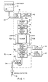
- volumetric pump 30 comprises a number of components that are serially arranged along a fluid path through the pump.
- a liquid 31 that is administered by volumetric pump 30 is supplied from a container 32 through flexible tubing 34.
- Liquid 31 enters volumetric pump 30 through a proximal portion 34a of the flexible tubing.
- the fluid path continues through a pumping portion 34b and exits the pump through a distal portion 34c of the flexible tubing.
- Distal portion 34c of the flexible tubing is connected to a needle/catheter 36 that is used to introduce liquid 31 output from the pump intravenously into a patient.
- volumetric pump 30 may also be used in other applications wherein distal portion 34c of the flexible tubing is connected to some other apparatus disposed downstream of volumetric pump 30.
- Flexible tubing 34 is continuous, but for purposes of this disclosure, is referred to as divided into the proximal, pumping, and distal portions 34a, 34b, and 34c, respectively; preferably, it comprises a polyvinyl chloride (PVC) disposable tube set, such as is customarily used to administer fluids intravenously to a patient.
- PVC polyvinyl chloride
- the tubing may have a 0.137" O.D. and 0.100" I.D.
- volumetric pump 30 includes a free flow latch 38, which clamps proximal portion 34a of the flexible tubing to prevent liquid 31 from container 32 flowing freely into a patient, due to head pressure.
- Free flow latch 38 does not restrict fluid flow during the normal pumping operation of volumetric pump 30, but is configured to automatically clamp proximal portion 34a of the flexible tubing when a door 78 (shown in FIGURES 2 and 3) on volumetric pump 30 is opened. While door 78 is closed, free fluid flow through volumetric pump 30 is otherwise precluded by volumetric pump 30, as explained below.
- the position of door 78 is sensed by a door position detector 62, producing a signal that prevents operation of volumetric pump 30 when door 78 is open.
- a tubing detector 40 is interconnected to free flow latch 38, and produces a signal indicative of the presence of flexible tubing 34 within free flow latch 38; operation of volumetric pump 30 is inhibited if the signal indicates that the flexible tubing is not in place.
- a balance block 42 rests against proximal portion 34a of flexible tubing 34 and serves to compensate for variations or changes in the elasticity of flexible tubing 34.
- the function and operation of balance block 42 are more fully explained below.
- proximal pressure sensor 44 which operates to sense the pressure of fluid within proximal portion 34a of the flexible tubing.
- Proximal pressure sensor 44 produces a signal indicative of fluid pressure in this portion of flexible tubing 34 for use in monitoring the operation of the pump and to determine if proximal portion 34a has become occluded.
- An inlet cracking valve 46 is disposed immediately downstream of proximal pressure sensor 44.
- Inlet cracking valve 46 functions in cooperation with a plunger 48 and an outlet cracking valve 52, which are disposed sequentially downstream of the inlet cracking valve, to provide the displacement of a volumetric quantity of fluid from pumping portion 34b of the flexible tubing by volumetric pump 30 and to generally isolate the volumetric pump from variations in proximal and distal fluid pressure, due, for example, to variations in the elevation of container 32, or variations in the back pressure of fluid in distal portion 34c of the flexible tubing.
- Tubing shapers 50a and 50b are disposed at each side of plunger 48 and act to rapidly reform pumping portion 34b of the flexible tubing as it refills with fluid during each pump cycle, insuring consistent volumetric refill with each pumping stroke.
- a flow detector 54 in accordance with the present invention is functionally connected with outlet cracking valve 52.
- Flow detector 54 produces a signal indicating whether fluid is successfully being pumped by volumetric pump 30 into distal portion 34c of the flexible tubing. As explained below, in response to this signal, medical personnel are alerted if container 31 has become empty of liquid 31 or if any other problem has prevented fluid flow from volumetric pump 30.
- a distal pressure sensor 56 produces a signal indicative of the fluid pressure within distal portion 34c of the flexible tubing, i.e., the output pressure of volumetric pump 30.
- the distal fluid pressure is used for monitoring the operation of volumetric pump 30 and for sensing an occlusion of flexible tubing 34.
- balance block 58 Immediately adjacent distal pressure sensor 56 is a balance block 58. Cooperating with outlet cracking valve 52, a balance block 58 compensates for changes or variations in the stiffness or elasticity of flexible tubing 34, in a manner similar to that in which balance block 42 cooperates with inlet cracking valve 46.
- Air sensor 60 is the last component along the fluid path through volumetric pump 30. Air sensor 60 detects the presence of air bubbles larger than a predefined volume in the fluid discharged from the volumetric pump, and produces a signal indicative of such air bubbles, which stops volumetric pump 30 and initiates an alarm to prevent a potentially harmful air embolism forming in the fluid being introduced into a patient through needle/catheter 36.
- Air sensor 60 comprises a generally conventional piezoelectric ultrasonic transmitter and receiver (not separately shown), spaced apart on opposite sides of distal portion 34c of the flexible tubing. The transmitter produces an ultrasonic signal that is transmitted through flexible tubing 34 to the receiver. Liquid present in flexible tubing 34 between the transmitter and receiver conveys the ultrasonic signal much more efficiently than does an air bubble.
- the receiver produces an electronic signal in response to the level of the ultrasonic signal reaching it, the amplitude of the electronic signal indicating whether an air bubble or liquid is present in flexible tubing 34 between the transmitter and receiver. Details of air sensor 60 are not illustrated because such devices are generally well known to those of ordinary skill in this art.
- Proximal pressure sensor 44, distal pressure sensor 56, air sensor 60, and flow detector 54 form a complete monitoring system to ensure that volumetric pump 30 is operating properly. To some extent, these components have redundant functions, but flow detector 54 serves as a final back-up for the monitoring system, since it detects whether the volumetric pump is performing its primary function, i.e., pumping liquid 31.
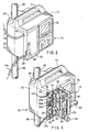
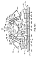
- volumetric pump 30 is illustrated in isometric view.
- volumetric pump 30 includes a molded plastic housing 70, having a handle 72 on its upper surface to facilitate carrying the volumetric pump to a point of use.
- a control panel 74 and a display 76 are disposed on the right side of the front surface of volumetric pump 30, and are respectively used by an operator for entry and display of data that controls the volumetric pump.
- clamp 88 On the back of housing 70 is formed a clamp 88, which is used to removably attach volumetric pump 30 to a post 86, for example at the bedside of a patient. Details of clamp 88 are not shown, since it is generally typical of those used with other types of medical apparatus intended for connection to vertical posts.
- door 78 is shown latched closed, the appropriate disposition for use of the volumetric pump, while in FIGURE 3, door 78 is shown in an open position.
- a latch handle 80 is pivoted upwardly so that door 78 can be swung open on a hinge 96, giving access to an inner cover 92 that defines the path followed by flexible tubing 34 through volumetric pump 30.
- free flow latch 38 clamps the flexible tubing closed to prevent liquid 31 in container 32 from free flowing through flexible tubing 34.
- the mechanism that actuates free flow latch 38 when door 78 is opened is not shown since it is not particularly relevant to the present invention.
- Flexible tubing 34 is angled upwardly where it passes through an entry slot 82 formed on the side of door 78, insuring that any of liquid 31 leaking from container 32 drips from a loop formed in flexible tubing 34 and does not run into volumetric pump 30.
- flexible tubing 34 is readily threaded into a channel 90 defined along the longitudinal center of inner cover 92.
- a pressure plate 94 disposed on the inner surface of door 78 comes into contact with flexible tubing 34 along the length of channel 90 as door 78 is closed and latched with handle 80.
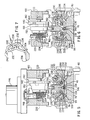
- FIGURES 4, 5, and 6 show details of the interior of volumetric pump 30.
- Pressure plate 94 defines a reference plane or surface in respect to each of the components of volumetric pump 30 that act to compress flexible tubing 34 and is mounted so that it floats on a plurality of helical coiled springs 212. Springs 212 bias pressure plate 94 away from the inner surface of door 78. When door 78 is closed, pressure plate 94 contacts inner cover 92 at several points. Helical springs 212, which are relatively stiff, are thus slightly compressed, and therefore accommodate variations in the tolerances of door 78 and other related parts that arise during construction of volumetric pump 30. Such tolerances might otherwise affect the position of the reference plane defined by pressure plate 94.
- frame 100 includes inlet cracking valve pivot mounts 102 and outlet cracking valve pivot mounts 104, about which inlet cracking valve 46 and outlet cracking valve 52 respectively pivot.
- Inlet cracking valve 46 contacts proximal portion 34a of the flexible tubing along a valve face 106a.
- outlet cracking valve 52 contacts distal portion 34c of the flexible tubing along a valve face 106b.
- the pivotal motion of inlet cracking valve 46 and outlet cracking valve 52 respectively varies the force with which valve faces 106a and 106b contact flexible tubing 34 to control fluid flow therethrough by compressing the flexible tubing against pressure plate 94.
- Plunger 48 compresses pumping portion 34b of the flexible tubing against pressure plate 94 to displace fluid from within a pumping chamber defined between the inlet and outlet cracking valves 46 and 52.
- volumetric pump 30 includes inlet and outlet cracking valves 46 and 52, it operates differently than the prior art plunger type peristaltic pumps, as will be apparent from the following disclosure.
- An inlet valve arm 108 extends upwardly from valve face 106a on inlet cracking valve 46.
- Disposed generally above inlet cracking valve pivot mounts 102 are flat metal spring flexures 110, which connect balance block 42 to a slot 134, formed on the back side of inlet valve arm 108. Flexures 110 are snapped within slot 134 and flex to enable inlet valve arm 108 to pivot valve face 106a away from pressure plate 94 through a greater angle than would otherwise be possible, without closing off fluid flow through flexible tubing 34 due to compression of the flexible tubing by balance block 42.
- Inlet cracking valve pivot mounts 102 are connected to downwardly depending pivot arms 136 on inlet cracking valve 46, at each side of flexible tubing 34, and are centered between balance block 42 and valve face 106a.
- the stiffness of flexible tubing 34 acts on balance block 42 and flexures 110, and the balance force developed as a function of this stiffness (or lack of elasticity) tends to pivot inlet valve face 106a against pressure plate 94, thereby increasing the force exerted by that part of inlet cracking valve 46 to compress the flexible tubing.
- the stiffness of flexible tubing 34 also resists compression by inlet valve face 106a to a similar extent. Accordingly, variations in the elasticity of flexible tubing 34 that affect the force required for inlet valve face 106a to compress the tubing are automatically compensated for by balance block 42.
- Inlet cracking valve 46 operates in three distinct modes, the force applied by valve face 106a to compress flexible tubing 34 being substantially different in each mode. Two different spring-bias forces act on inlet valve arm 108. A fluid flow control force is applied to inlet valve arm 108 by a flat metal spring cracking flexure 112, acting against a knob 114, which is disposed at one end of inlet valve arm 108. The additional force necessary to compress flexible tubing 34 sufficiently to completely close off fluid flow past inlet cracking valve 46 is supplied by a flat metal spring closure flexure 120. Closure flexure 120 acts upon a side arm 116, disposed on one side of inlet valve arm 108.
- the combined force provided by cracking flexure 112 and closure flexure 120 pivots inlet cracking valve 46 about a pivot axis extending through inlet cracking valve pivot mounts 102, to completely block fluid flow through flexible tubing 34.
- An inlet valve cam follower 122 selectively determines whether cracking flexure 112 and closure flexure 120 apply force against inlet valve arm 108 and thus determines the three modes in which inlet cracking valve 42 operates.
- Inlet valve cam follower 122 includes a roller 124 rotatably mounted in a hood 126, which is attached via an inlet follower flexure 128 to a plurality of blocks 130.
- Blocks 130 are also used in mounting cracking flexure 112 and closure flexure 120 to a bracket 135 and to provide appropriate spacing between these flexures and bracket 135.
- Bolts 132 connect the ends of each of these flexures to bracket 135, which comprises a portion of frame 100.
- Roller 124 rolls along an inlet valve cam track 140, disposed on a rotating cam assembly 142.
- Cam assembly 142 turns on a camshaft 144, which at each of its ends is mounted to frame 100 in bearings 220 (see FIGURES 5 and 6).
- a motor shaft 148 extends downwardly from a motor 146, and a helical gear 224 on motor shaft 148 drivingly engages gear teeth 222, which are formed on one end of cam assembly 142, causing the cam assembly to rotate in a clockwise direction, as viewed in FIGURE 4.
- inlet valve cam follower 122 radially back and forth so as to control the forces applied to inlet valve arm 108.
- hood 126 is forced radially back against closure flexure 120, it lifts the closure flexure away from side arm 116, eliminating the force normally exerted by the closure flexure against the side arm and thereby reducing the total force exerted by valve face 106a against flexible tubing 34.
- inlet cracking valve 46 is in a "cracking mode.”
- inlet cracking valve 46 is in an open mode, wherein liquid 31 freely flows from container 32 through proximal portion 34a of the flexible tubing and into pumping portion 34b.
- Flexures 110 bend as valve face 106a pivots away from pressure plate 94, so that balance block 42 does not close off fluid flow through proximal portion 34a of the flexible tubing.
- valve face 106a compresses flexible tubing 34 against pressure plate 94 sufficiently to completely block fluid flow through the flexible tubing. In this configuration, inlet cracking valve 46 is in a "closed mode.”
- An outlet valve cam track 150 is disposed between inlet valve cam track 140 and a plunger cam track 152.
- Plunger cam track 152 provides a surface at varying radii about camshaft 144 for actuating plunger 48 to compress pumping portion 34b of the flexible tubing against pressure plate 94.
- a roller 154 is rotatably mounted on a base 156 of plunger 48, and is thus disposed to roll along plunger cam track 152. Also mounted on base 156, at opposite sides of roller 154, are tubing shaper rollers 160. The disposition of tubing shaper rollers 160 is more clearly shown in FIGURES 5 and 6, and their operation in respect to shaping flexible tubing 34 is disclosed in detail below.
- cam assembly 142 includes a torque compensation track 170.
- a conically-shaped torque compensation roller 172 rolls along torque compensation track 170, applying a rotational torque to cam assembly 142 that compensates for an opposite torque resulting from rapid changes in the shape of inlet valve cam track 140, outlet valve cam track 150, and plunger cam track 152.
- Torque compensation roller 172 is mounted on a flat metal spring torque compensation flexure 174 that applies a biasing force to cam assembly 142.
- outlet cracking valve 52 has a generally "Y-shaped” configuration and includes an outlet valve arm 180, which is connected to outlet valve face 106b and to balance block 58.
- pivot arms 136 extend downwardly, connecting to outlet cracking valve pivot mounts 104 on frame 100.
- Balance block 58 rests on distal portion 34c of the flexible tubing and develops a force proportional to the stiffness (or lack of elasticity) of flexible tubing 34, which tends to increase the compression force applied against flexible tubing 34 by outlet valve face 106b to compensate or balance the resistance to compression caused by the stiffness (or lack of elasticity) of the flexible tubing.
- balance block 58 compensates for such changes and variations in respect to outlet cracking valve 52.
- outlet cracking valve 52 is never pivoted to an open mode like inlet cracking valve 46
- balance block 58 is integrally attached to outlet valve arm 180. Flexures 110 are not required, since the extent of pivotal rotation of outlet cracking valve 52 is substantially more limited than for inlet cracking valve 46. At all times, even when volumetric pump 30 is not pumping fluid, either inlet cracking valve 46 or outlet cracking valve 52 is in its closed mode, preventing liquid 31 from free flowing through flexible tubing 34.
- outlet cracking valve 52 is in its closed mode, compressing flexible tubing 34 against pressure plate 94 sufficiently to block fluid flow therethrough.
- a flat metal spring cracking flexure 182 applies force against a knob 184 on the top of outlet valve arm 180.
- a flat metal spring closure flexure 188 applies a biasing force against a side arm 186 that extends outwardly from the side of outlet valve arm 180.
- An outlet valve cam follower 190 includes a roller 192, which rolls along outlet valve cam track 150.
- Roller 192 is rotatably mounted within a hood 194, which is connected to a flat metal spring follower flexure 196.
- follower flexure 196 spring biases roller 192 into contact with outlet valve cam track 150.
- the lower ends of follower flexure 196, cracking flexure 182, and closure flexure 188 are all secured at blocks 130 to bracket 135 by bolts 132, just as the corresponding elements are in respect to inlet cracking valve 46.
- outlet valve cam follower 190 follows outlet valve cam track 150, hood 194 periodically contacts closure flexure 188, lifting it away from side arm 186 so that the flow control force provided by cracking flexure 182, added to the balance force developed by balance block 58, is transmitted to valve face 106b, thereby compressing flexible tubing 34 against pressure plate 94 with a cracking force.
- outlet cracking valve 52 is in its cracking mode.
- the first preferred embodiment of flow detector 54 comprises a strain gauge 198, which is mounted on cracking flexure 182. Strain gauge 198 develops an output signal corresponding to the stress developed in cracking flexure 182, and therefore indicates that outlet valve arm 180 is rotating to allow fluid flow past outlet cracking valve 52. Accordingly, strain gauge 198 determines whether fluid is being pumped through distal portion 34c of the flexible tubing as a result of displacement by plunger 48. If pumping portion 34b of the flexible tubing contains a relatively large proportion of air or other compressible gaseous fluid, plunger 48 cannot develop sufficient fluid pressure to overcome the cracking force exerted by cracking flexure 182 and balance block 58.
- strain gauge 198 fails to detect the stress of cracking flexure 182 that would have occurred if outlet valve arm 180 had pivoted open to allow fluid flow past outlet cracking valve 52 during a pumping stroke of plunger 48. Accordingly, the signal from strain gauge 198 is used to detect whether container 32 has run dry, allowing air to fill pumping portion 34b of the flexible tubing, or whether the flow of liquid 31 into volumetric pump 30 has otherwise been interrupted. The signal produced by strain gauge 198 is simply used as a "go/no-go" signal as opposed to a signal that is accurately proportional to the movement of outlet valve arm 180. This go/no-go fluid flow detection signal is used to stop volumetric pump 30 and initiate an alarm when the expected fluid flow is not obtained, thereby alerting medical personnel of the problem so that it can be corrected.
- Proximal pressure sensor 44 comprises a block 204, which is spring-biased into contact with proximal portion 34a of the flexible tubing and is disposed between inlet cracking valve 46 and balance block 42.
- a spring-bias force for proximal pressure sensor 44 is provided by two pairs of longitudinally extending flexures 202, disposed on each side of plunger 48. Flexures 202 are connected to support plates 266 on frame 100 by fasteners 206 at about the midpoint of the flexures.
- One of the four flexures 202 connecting block 204 to support plates 266 includes a strain gauge 200, which responds to stress developed in that flexure 202 as a function of fluid pressure within proximal portion 34a of the flexible tubing. As the fluid pressure increases within this portion of flexible tubing 34, flexures 202 connected to block 204 experience increased stress, producing a corresponding change in the output signal from strain gauge 200.
- distal pressure sensor 56 comprises a block 210, which is connected to the other ends of flexures 202.
- a strain gauge 208 is disposed on one of the four flexures, intermediate block 210 and one of the support plates 266. Strain gauge 208 produces a signal corresponding to the fluid pressure within distal portion 34c of the flexible tubing, based upon stress developed in flexures 202 as a result of that pressure.
- Distal pressure sensor 56 can be used to determine if distal portion 34c of the flexible tubing has been kinked, interrupting fluid flow through flexible tubing 34, for example, as might occur if a patient rolled over onto flexible tubing 34. Such a condition causes a notable increase in the distal fluid pressure that triggers an alarm and shuts off volumetric pump 30. If distal pressure sensor 56 should fail, flow detector 54 will also detect obstruction of fluid flow through distal portion 34c of the flexible tubing in response to cessation of fluid flow from volumetric pump 30.
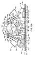
- tubing shapers 50a and 50b are disclosed. Since it is preferable to use relatively low cost PVC tubing in connection with volumetric pump 30, tubing shapers 50a and 50b are provided to ensure consistent operation and volumetric capacity of pumping portion 34b of the flexible tubing throughout the entire operating range of volumetric pump 30. At relatively high pumping rates, PVC tubing does not fully recover to its normal round uncompressed shape from a compressed condition rapidly enough to fill completely with fluid. Accordingly, the volumetric displacement of fluid within the PVC tubing that occurs with each pumping stroke is less than desired.
- tubing shapers 50a and 50b force pumping portion 34b of the flexible tubing to recover rapidly to its maximum volumetric capacity, i.e., to open sufficiently so that the desired amount of liquid 31 fills the pumping chamber defined by pumping portion 34b of the flexible tubing.
- Each tubing shaper 50a and 50b comprises an angled arm 234, terminating at one end in a longitudinally extending jaw 236.
- Arms 234 are attached to frame 100 at pivot mounts 230, about which arms 234 rotate as tubing shaper rollers 160 roll along inner surfaces 232 of arms 234.
- the reciprocating up-and-down motion of plunger 48 along its reciprocation axis inherently acts on tubing shaper rollers 160 in "lock-step", causing jaws 236 to pinch pumping portion 34b of the flexible tubing at the proper time, thereby reforming flexible tubing 34 into the required pumping volume or capacity as plunger 48 lifts away from pressure plate 94.
- tubing shapers 50a and 50b are shown moving in opposite directions, away from pumping portion 34b of the flexible tubing as plunger 48 descends to compress flexible tubing 34, displacing fluid from pumping portion 34b.
- plunger 48 is shown moving upwardly away from pressure plate 94, acting on tubing shaper rollers 160 to force opposing jaws 236 to swing inwardly toward each other in order to reshape pumping portion 34b of the flexible tubing so that it achieves its desired volumetric capacity.
- plunger cam track 152 is sized and shaped so that plunger 48 never completely compresses pumping portion 34b of the flexible tubing, even at the lowermost point of the plunger's reciprocal stroke. In addition, at the top of its reciprocal stroke, plunger 48 remains in contact with pumping portion 34b of the flexible tubing.
- the range of diametrical compression of flexible tubing 34 is from about 15% at the top of the pumping stroke to about 85% at the bottom of the pumping stroke of plunger 48.
- a wedge-shaped slot 240 is provided in the upper outer portion of arms 234.
- a wedge-shaped insert 238 is driven into wedge-shaped slot 240, deflecting the upper portion of arm 234 through an angle, as indicated by reference numeral 242.
- Angle 242 is determined by use of an appropriate calibration jig (not shown) during manufacture of tubing shapers 50a and 50b, or during assembly of these components in volumetric pump 30.
- FIGURE 8 Details of inlet cracking valve 46 are shown in FIGURE 8, and details of outlet cracking valve 52 are shown in FIGURE 9.
- FIGURE 8 more clearly illustrates side arm 116 and V-shaped side arm 118 at the top of inlet valve arm 108.
- FIGURE 9 the specific disposition of side arm 186 in respect to outlet valve cam follower 190, closure flexure 188, and cracking flexure 182 is also more clearly shown.
- outlet valve arm 180 may be mounted proximal outlet valve arm 180 to produce a signal indicative of its pivotal motion.
- the pivotal movement of outlet valve arm 180 as fluid flows past outlet cracking valve 52 can be detected using an optical sensor 300, as shown in FIGURE 11.
- the upper end of outlet valve arm 180 is modified to include a tab 308. Centered within tab 308 is a triangular shaped aperture 306. Disposed on opposite sides of tab 308 are a light emitting diode (LED) 302 and a phototransistor 304.
- LED light emitting diode
- a linear variable displacement transformer (LVDT) 318 is used to detect whether outlet valve arm 180 has moved to allow fluid flow from volumetric pump 30 past outlet cracking valve 52.
- the upper end of outlet valve arm 180 is modified to include a transverse tab 326.
- Tab 326 abuts against a ferrous metal core 322, which extends from the center LVDT 318.
- LVDT 318 also comprises a plurality of electro-magnetic coils 320 including a primary coil and two secondary coils (not separately shown).
- a bracket 324 supports electro-magnetic coils 320 at a fixed position with respect to the movement of ferrous metal core 322.
- a helical coil spring (not shown) inside LVDT 318 biases ferrous magnetic core 322 into contact with tab 326.
- a Hall sensor could be mounted adjacent outlet valve arm 180 to detect the motion of a magnet bonded to the outlet valve arm, as outlet cracking valve 52 opens to enable fluid flow from volumetric pump 30.
- flow detector 54 may also comprise a variable capacitor that changes capacitance value as outlet valve arm 180 pivots.
- LVDT 318 and a variable capacitor are simply different types of variable reactance sensors. Clearly, those of ordinary skill in the art will recognize that these and other types of sensors for detecting motion of outlet valve arm 180 can serve as an indication of fluid flow from volumetric pump 30.
- FIGURE 13 illustrates a circuit 340 that is used in connection with strain gauge 198, optical sensor 300, LVDT 318, or with the alternative sensors that can comprise flow detector 54 (as discussed above) to produce a signal indicative of movement of outlet valve arm 180 and thus indicative of fluid flow from volumetric pump 30.
- a sensor block 342 produces a signal indicating whether outlet valve arm 180 has moved to enable fluid flow from the volumetric pump.
- the signal produced by the sensor in block 342 is input to a signal interface 344.
- the function performed by interface 344 depends upon the type of sensor used to monitor the motion of outlet valve arm 180.
- signal interface 344 comprises a simple amplifier used to amplify the signal from photo transistor
- signal interface 344 comprises a differential amplifier that produces a signal indicative of the difference in electromagnetic coupling between the primary coil and two secondary coils comprising electro-magnetic coils 320 as ferrous metal core 322 is moved into the center of the LVDT.
- a signal output from signal interface 344 comprises an analog DC level that is input to a comparator block 348, for comparison to a reference analog signal produced in block 346. If, for example, the signal output from signal interface block 344 exceeds the reference signal level from reference block 346, comparator 348 generates a logic level signal indicating that outlet valve arm 180 has moved the required distance representative of fluid flow from volumetric pump 30. Thus the logic signal from comparator 348 is a flow detection signal, as shown in block 350, which is input to a system controller 280 shown in FIGURE 14.
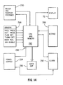
- system controller 280 includes a microprocessor CPU and memory block 282.
- Software algorithms that control volumetric pump 30 are implemented within the CPU in response to input control data provided by an operator on a keypad 286. For example, an operator might enter specific times during which volumetric pump 30 should administer a prescribed volume of liquid 31 intravenously to a patient, at a prescribed flow rate.
- the control data entered via keypad 286 are shown on display 76.
- CPU and memory block 282 actuates the motor at the required time, controls it to administer the prescribed volume of liquid 31 at the prescribed rate, and keeps track of its progress through the pumping cycle in respect to signals provided by various sensors on volumetric pump 30 to detect problems that may affect the performance of the volumetric pump. For example, if flow detector 54 fails to produce a signal indicating that fluid has forced open outlet cracking valve 52 as plunger 48 has completed a pumping segment of the pumping cycle, the CPU causes both a visual and audio audible signal to be generated by an alarm 292, to alert medical personnel that volumetric pump 30 has ceased pumping liquid 31 to the patient.
- a data output path 296 is optionally provided for CPU and memory block 282.
- a power supply 294 provides power for CPU and memory block 282 and for alarm 292.
- the senor is considered to be a fluid flow detector for determining that a fluid is flowing out of an outlet port of a positive displacement pump as the pump compresses flexible tubing to displace fluid from within a pumping portion of the flexible tubing, comprising:
- the above fluid flow detector can be seen to have the pressure developed within the pumping portion of the flexible tubing by the pump compressing a gaseous fluid is always less than that required to produce a force in excess of the cracking force, so that compressed gaseous fluid cannot flow past the outlet valve member and out of the pump.
- the deflection sensor is further operative to detect whether a liquid is being positively displaced or a gaseous fluid is being compressed in the pumping portion of the flexible tubing, since the gaseous fluid does not develop sufficient pressure to force open the outlet valve member.
- the spring bias means comprise an elongate flat flexure that is mounted on the pump and abuts against the outlet valve member
- said deflection sensor comprises a strain gauge attached to the flexure, which produces the signal, said signal being proportional to a stress applied by the outlet valve member to deflect the flexure, said deflection sensor being disposed on the flexure intermediate a point where the flexure is mounted to the pump and point where it abuts the outlet valve member.
- the flow detector comprises an optical sensor, or a Hall effect sensor, or a variable reactance sensor.
Landscapes
- Health & Medical Sciences (AREA)
- Vascular Medicine (AREA)
- Engineering & Computer Science (AREA)
- Anesthesiology (AREA)
- Biomedical Technology (AREA)
- Heart & Thoracic Surgery (AREA)
- Hematology (AREA)
- Life Sciences & Earth Sciences (AREA)
- Animal Behavior & Ethology (AREA)
- General Health & Medical Sciences (AREA)
- Public Health (AREA)
- Veterinary Medicine (AREA)
- Reciprocating Pumps (AREA)
- Infusion, Injection, And Reservoir Apparatuses (AREA)
Applications Claiming Priority (2)
| Application Number | Priority Date | Filing Date | Title |
|---|---|---|---|
| US07/494,201 US5039279A (en) | 1990-03-15 | 1990-03-15 | Sensor for detecting fluid flow from a positive displacement pump |
| US494201 | 1995-06-23 |
Publications (1)
| Publication Number | Publication Date |
|---|---|
| EP0447985A1 true EP0447985A1 (de) | 1991-09-25 |
Family
ID=23963476
Family Applications (1)
| Application Number | Title | Priority Date | Filing Date |
|---|---|---|---|
| EP91104039A Ceased EP0447985A1 (de) | 1990-03-15 | 1991-03-15 | Verdrängungspumpe |
Country Status (5)
| Country | Link |
|---|---|
| US (1) | US5039279A (de) |
| EP (1) | EP0447985A1 (de) |
| JP (1) | JPH04224288A (de) |
| AU (1) | AU641734B2 (de) |
| CA (1) | CA2038314A1 (de) |
Cited By (31)
| Publication number | Priority date | Publication date | Assignee | Title |
|---|---|---|---|---|
| EP0551088A1 (de) * | 1992-01-06 | 1993-07-14 | Baxter International Inc. | Peristaltische Pumpe mit verbesserter Schaltung zur Erkennung von falsch geladenen Schläuchen |
| EP0615763A3 (de) * | 1993-03-16 | 1994-10-26 | Transmed Medtech Gmbh | Aufwärm- und Auftaugerät. |
| WO1995031233A1 (en) * | 1994-05-13 | 1995-11-23 | Abbott Laboratories | Disposable fluid infusion pumping chamber cassette having a push button flow stop thereon |
| WO1997037703A1 (en) * | 1996-04-10 | 1997-10-16 | Baxter International Inc. | Volumetric infusion pump |
| WO1998007462A1 (de) * | 1996-08-20 | 1998-02-26 | Backes Claus H | Medizinisches hochdruckinjektionssystem |
| WO1998056453A1 (en) * | 1997-06-12 | 1998-12-17 | Abbott Laboratories | Pump with anti-free flow feature |
| GB2338758A (en) * | 1996-04-10 | 1999-12-29 | Baxter Int | Infusion pump having tube present sensors |
| WO2000044420A1 (en) * | 1999-02-01 | 2000-08-03 | Baxter International Inc. | Metered dose infusion pump and method |
| AU723365B2 (en) * | 1996-04-10 | 2000-08-24 | Baxter International Inc. | An infusion pump with a tube present sensor |
| US6213723B1 (en) | 1996-06-24 | 2001-04-10 | Baxter International Inc. | Volumetric infusion pump |
| AU742059B2 (en) * | 1996-04-10 | 2001-12-13 | Baxter International Inc. | Method of placing sensors in contact with a tube |
| AU750280B2 (en) * | 1996-04-10 | 2002-07-11 | Baxter International Inc. | Method of placing sensors in contact with a tube |
| WO2003041787A3 (de) * | 2001-11-15 | 2004-01-29 | Arcomed Ag | Sicherheitsvorrichtung für eine infusionspumpe |
| EP1535637A1 (de) * | 2003-11-28 | 2005-06-01 | Woo Young Medical Co., Ltd. | Automatische Infusionsvorrichtung |
| US6997905B2 (en) | 2002-06-14 | 2006-02-14 | Baxter International Inc. | Dual orientation display for a medical device |
| US7018361B2 (en) | 2002-06-14 | 2006-03-28 | Baxter International Inc. | Infusion pump |
| WO2007058951A3 (en) * | 2005-11-10 | 2007-08-23 | Iradimed Corp | Peristaltic liquid infusion apparatus |
| US7267661B2 (en) | 2002-06-17 | 2007-09-11 | Iradimed Corporation | Non-magnetic medical infusion device |
| US7404809B2 (en) | 2004-10-12 | 2008-07-29 | Iradimed Corporation | Non-magnetic medical infusion device |
| US8105282B2 (en) | 2007-07-13 | 2012-01-31 | Iradimed Corporation | System and method for communication with an infusion device |
| US8105269B2 (en) | 2008-10-24 | 2012-01-31 | Baxter International Inc. | In situ tubing measurements for infusion pumps |
| US8137083B2 (en) | 2009-03-11 | 2012-03-20 | Baxter International Inc. | Infusion pump actuators, system and method for controlling medical fluid flowrate |
| EP2487393A1 (de) * | 2011-02-14 | 2012-08-15 | WMF Württembergische Metallwarenfabrik AG | Klemmventil |
| US8382447B2 (en) | 2009-12-31 | 2013-02-26 | Baxter International, Inc. | Shuttle pump with controlled geometry |
| US8567235B2 (en) | 2010-06-29 | 2013-10-29 | Baxter International Inc. | Tube measurement technique using linear actuator and pressure sensor |
| US10143795B2 (en) | 2014-08-18 | 2018-12-04 | Icu Medical, Inc. | Intravenous pole integrated power, control, and communication system and method for an infusion pump |
| US10918787B2 (en) | 2015-05-26 | 2021-02-16 | Icu Medical, Inc. | Disposable infusion fluid delivery device for programmable large volume drug delivery |
| USD939079S1 (en) | 2019-08-22 | 2021-12-21 | Icu Medical, Inc. | Infusion pump |
| US11213619B2 (en) | 2013-11-11 | 2022-01-04 | Icu Medical, Inc. | Thermal management system and method for medical devices |
| US11268506B2 (en) | 2017-12-22 | 2022-03-08 | Iradimed Corporation | Fluid pumps for use in MRI environment |
| USD1052728S1 (en) | 2021-11-12 | 2024-11-26 | Icu Medical, Inc. | Medical fluid infusion pump |
Families Citing this family (79)
| Publication number | Priority date | Publication date | Assignee | Title |
|---|---|---|---|---|
| US5803712A (en) | 1988-05-17 | 1998-09-08 | Patient Solutions, Inc. | Method of measuring an occlusion in an infusion device with disposable elements |
| GB8825816D0 (en) | 1988-11-04 | 1988-12-07 | Danby Medical Eng Ltd | Pumping device |
| US5219279A (en) * | 1990-03-15 | 1993-06-15 | Abbott Laboratories | Volumetric pump with pump plunger support and method |
| US5120096A (en) * | 1990-08-23 | 1992-06-09 | Baxter International Inc. | Misloaded IV tube detector for an IV pump |
| US5090877A (en) * | 1990-08-23 | 1992-02-25 | Baxter International Inc. | Misloaded iv tube detector for an iv pump |
| USD332066S (en) | 1990-09-06 | 1992-12-29 | Clean Earth Technology, Inc. | Control panel for a liquid waste recovery system |
| GB2252798B (en) * | 1991-02-14 | 1994-07-27 | Danby Medical Ltd | Pumping apparatus |
| DE69219726T2 (de) * | 1991-06-10 | 1997-11-27 | Baxter Int | Intravenöse dosierungen überwachende vorrichtung |
| US5290239A (en) * | 1991-09-26 | 1994-03-01 | Baxter International, Inc. | Intravenous tube safety apparatus |
| US5482438A (en) * | 1994-03-09 | 1996-01-09 | Anderson; Robert L. | Magnetic detent and position detector for fluid pump motor |
| US5482446A (en) * | 1994-03-09 | 1996-01-09 | Baxter International Inc. | Ambulatory infusion pump |
| US5658133A (en) * | 1994-03-09 | 1997-08-19 | Baxter International Inc. | Pump chamber back pressure dissipation apparatus and method |
| US5575632A (en) * | 1994-09-12 | 1996-11-19 | Ivac Medical Systems, Inc. | Engineered pumping segment |
| US5567120A (en) * | 1994-10-13 | 1996-10-22 | Sigma International | Electronic infusion device and novel roller clamp holden therefor |
| US5721382A (en) * | 1995-05-01 | 1998-02-24 | Kriesel; Marshall S. | Apparatus for indicating fluid pressure within a conduit |
| US5962794A (en) * | 1995-05-01 | 1999-10-05 | Science Incorporated | Fluid delivery apparatus with reservior fill assembly |
| US6293159B1 (en) * | 1995-05-01 | 2001-09-25 | Science Incorporated | Fluid delivery apparatus with reservoir fill assembly |
| US6158269A (en) * | 1995-07-13 | 2000-12-12 | Bayer Corporation | Method and apparatus for aspirating and dispensing sample fluids |
| US5750881A (en) * | 1995-07-13 | 1998-05-12 | Chiron Diagnostics Corporation | Method and apparatus for aspirating and dispensing sample fluids |
| US5641006A (en) * | 1995-07-13 | 1997-06-24 | Chiron Diagnostics Corporation | Liquid supply apparatus and method of operation |
| US5720598A (en) * | 1995-10-04 | 1998-02-24 | Dowell, A Division Of Schlumberger Technology Corp. | Method and a system for early detection of defects in multiplex positive displacement pumps |
| US5718569A (en) * | 1996-01-11 | 1998-02-17 | Abbott Laboratories | Dual plunger cassette pump |
| US5840071A (en) * | 1996-12-18 | 1998-11-24 | Science Incorporated | Fluid delivery apparatus with flow indicator and vial fill |
| US5964583A (en) * | 1997-10-15 | 1999-10-12 | Baxter International Inc. | Elastomerically assisted peristaltic pump |
| US6622542B2 (en) * | 2001-03-20 | 2003-09-23 | Therox, Inc. | Bubble detector and method of use thereof |
| EP1476209B1 (de) * | 2002-02-18 | 2008-07-30 | Danfoss A/S | Vorrichtung zur verabreichung eines medikaments in flüssiger form |
| MXPA05000951A (es) * | 2002-07-24 | 2005-05-16 | Deka Products Lp | Sensor de desplazamiento optico para dispositivos de infusion. |
| EP1617888B1 (de) | 2003-04-23 | 2019-06-12 | Valeritas, Inc. | Hydraulisch aktivierte pumpe für langzeitabgabe von medikamenten |
| US7152469B2 (en) * | 2004-01-13 | 2006-12-26 | Baxter International Inc. | Fluid flow sensor, method and system |
| US7092797B2 (en) * | 2004-05-25 | 2006-08-15 | Sherwood Services Ag | Flow monitoring system for a flow control apparatus |
| WO2006014425A1 (en) | 2004-07-02 | 2006-02-09 | Biovalve Technologies, Inc. | Methods and devices for delivering glp-1 and uses thereof |
| US7628590B2 (en) * | 2005-02-16 | 2009-12-08 | Sterling Investments Lc | Method and apparatus for reducing free flow risk |
| CN103239773B (zh) | 2006-03-30 | 2015-08-26 | 瓦莱里塔斯公司 | 多筒式流体递送器械 |
| US7958915B2 (en) * | 2006-06-16 | 2011-06-14 | Maguire Stephen B | Liquid color gravimetric metering apparatus and methods |
| US7980834B2 (en) * | 2006-06-16 | 2011-07-19 | Maguire Stephen B | Liquid color injection pressure booster pump and pumping methods |
| US20070292288A1 (en) * | 2006-06-16 | 2007-12-20 | Maguire Stephen B | Multiple pusher liquid color pump |
| US8092070B2 (en) | 2006-06-17 | 2012-01-10 | Maguire Stephen B | Gravimetric blender with power hopper cover |
| US10201915B2 (en) | 2006-06-17 | 2019-02-12 | Stephen B. Maguire | Gravimetric blender with power hopper cover |
| US12135019B2 (en) * | 2007-09-06 | 2024-11-05 | Deka Products Limited Partnership | Product dispensing system |
| US11634311B2 (en) | 2007-09-06 | 2023-04-25 | Deka Products Limited Partnership | Product dispensing system |
| US10859072B2 (en) * | 2007-09-06 | 2020-12-08 | Deka Products Limited Partnership | Product dispensing system |
| US10562757B2 (en) | 2007-09-06 | 2020-02-18 | Deka Products Limited Partnership | Product dispensing system |
| US8353864B2 (en) | 2009-02-18 | 2013-01-15 | Davis David L | Low cost disposable infusion pump |
| US8197235B2 (en) | 2009-02-18 | 2012-06-12 | Davis David L | Infusion pump with integrated permanent magnet |
| JP5428785B2 (ja) * | 2009-11-12 | 2014-02-26 | 株式会社リコー | 輸液ポンプモジュール |
| JP2011152407A (ja) * | 2009-12-28 | 2011-08-11 | Ricoh Co Ltd | 輸液ポンプモジュール |
| CA2786258C (en) | 2009-12-31 | 2018-10-23 | Deka Products Limited Partnership | Infusion pump assembly |
| US9677555B2 (en) | 2011-12-21 | 2017-06-13 | Deka Products Limited Partnership | System, method, and apparatus for infusing fluid |
| US8800821B2 (en) * | 2010-02-16 | 2014-08-12 | Maguire Products, Inc. | Disposable low-cost pump in a container for liquid color dispensing |
| JP2012066004A (ja) * | 2010-09-27 | 2012-04-05 | Ricoh Co Ltd | 送液システム、送液方法及びプログラム |
| US8558408B2 (en) | 2010-09-29 | 2013-10-15 | General Electric Company | System and method for providing redundant power to a device |
| US8546984B2 (en) * | 2010-11-03 | 2013-10-01 | Nidec Motor Corporation | Pump motor control assembly |
| US8278779B2 (en) | 2011-02-07 | 2012-10-02 | General Electric Company | System and method for providing redundant power to a device |
| US9675756B2 (en) | 2011-12-21 | 2017-06-13 | Deka Products Limited Partnership | Apparatus for infusing fluid |
| US11295846B2 (en) | 2011-12-21 | 2022-04-05 | Deka Products Limited Partnership | System, method, and apparatus for infusing fluid |
| US10563681B2 (en) | 2011-12-21 | 2020-02-18 | Deka Products Limited Partnership | System, method, and apparatus for clamping |
| US9188118B2 (en) | 2012-06-15 | 2015-11-17 | Stephen B. Maguire | Injection molded diaphragm pump for liquid color with quick release |
| US9599265B2 (en) | 2012-06-15 | 2017-03-21 | Stephen B. Maguire | Multiple plate quick disconnect sandwich fitting |
| US9637283B2 (en) | 2012-06-15 | 2017-05-02 | Stephen B. Maguire | Quarter turn adapter connective outlet fitting for liquid color dispensing |
| US9850888B2 (en) | 2012-06-15 | 2017-12-26 | Stephen B. Maguire | Molded diaphragm liquid color pump |
| EP2917580B1 (de) * | 2012-11-09 | 2016-12-21 | Fresenius Vial SAS | Verfahren zum betrieb einer peristaltischen pumpe |
| US9359885B2 (en) * | 2013-03-15 | 2016-06-07 | Baxter International Inc. | Acoustic line tracing system and method for fluid transfer system |
| US10597513B2 (en) | 2013-07-17 | 2020-03-24 | Stephen B. Maguire | Cottonseed oil based additive compositions for plastics molding and extrusion |
| US9708462B2 (en) | 2013-07-17 | 2017-07-18 | Stephen B. Maguire | Liquid color composition with cottonseed oil base |
| US11795297B2 (en) | 2013-07-17 | 2023-10-24 | Stephen B. Maguire | Plastics coloring using cottonseed oil-based liquid color compositions |
| US9796123B2 (en) | 2013-12-13 | 2017-10-24 | Stephen B. Maguire | Dripless liquid color feed throat adaptor and method for dripless liquid color delivery |
| EP3103489B1 (de) * | 2014-02-07 | 2023-11-29 | Terumo Kabushiki Kaisha | Extrakorporale zirkulationsvorrichtung umfassend eine tubusklemme |
| US9841010B2 (en) | 2014-02-14 | 2017-12-12 | Stephen B. Maguire | Method and apparatus for closed loop automatic refill of liquid color |
| US10138075B2 (en) | 2016-10-06 | 2018-11-27 | Stephen B. Maguire | Tower configuration gravimetric blender |
| AU2015318119B2 (en) | 2014-09-18 | 2019-07-11 | Deka Products Limited Partnership | Apparatus and method for infusing fluid through a tube by appropriately heating the tube |
| US10245373B2 (en) * | 2014-12-01 | 2019-04-02 | Carefusion 2200, Inc. | Pump cassettes with positioning feature and infusion pump systems |
| EP3415733A1 (de) * | 2017-06-14 | 2018-12-19 | MEAS France | Fluidqualitätssensor zur messung der qualität eines fluids, sensoranordnung und anordnung für verbrennungsmotoren mit einem fluidqualitätssensor |
| MY199912A (en) | 2018-08-16 | 2023-11-29 | Deka Products Lp | Medical pump |
| CN111494753B (zh) | 2019-01-31 | 2024-02-13 | 贝克顿·迪金森公司 | 药物输送装置、药物输送笔和药物输送注射器 |
| US11813431B2 (en) | 2019-03-29 | 2023-11-14 | Honeywell International Inc. | Fluid flow sensor |
| US11517670B2 (en) * | 2019-05-10 | 2022-12-06 | Honeywell International Inc. | Fluid sensor |
| WO2021222619A1 (en) * | 2020-05-01 | 2021-11-04 | Bayer Healthcare Llc | Pinch valve for fluid injector system |
| US11788918B2 (en) | 2020-06-18 | 2023-10-17 | Trevillyan Labs, Llc | Fluid detection fabric |
| CN114396377B (zh) * | 2021-12-20 | 2024-05-24 | 烟台杰瑞石油服务集团股份有限公司 | 一种压裂泵检测方法、系统、设备及存储介质 |
Citations (7)
| Publication number | Priority date | Publication date | Assignee | Title |
|---|---|---|---|---|
| DE2118692A1 (de) * | 1970-04-21 | 1972-04-13 | Dainippon Toryo Kk | Blockierte Isocyanatpolymere und Verfahren zu ihrer Herstellung |
| DE2214735A1 (de) * | 1972-03-25 | 1973-09-27 | Appelt Otto Heinrich Dipl Ing | Elektronischer durchflussmesser fuer fluessigkeiten |
| DE2528960A1 (de) * | 1974-07-15 | 1976-02-05 | Origo | Foerderpumpe fuer intravenoes einzufuehrende substanzen |
| WO1981001656A1 (en) * | 1979-12-13 | 1981-06-25 | Baxter Travenol Lab | Method and apparatus for metered infusion of fluids |
| DE3042622A1 (de) * | 1980-11-12 | 1982-05-19 | Battelle-Institut E.V., 6000 Frankfurt | Verfahren und vorrichtung zur ueberwachung der geschwindigkeit bzw. vom durchsatz von stroemungen |
| US4758228A (en) * | 1986-11-17 | 1988-07-19 | Centaur Sciences, Inc. | Medical infusion pump with sensors |
| EP0293592A2 (de) * | 1987-05-01 | 1988-12-07 | Abbott Laboratories | Wegwerfbare Infusionskassette mit Pumpenkammer sowie Triebwerk dafür |
Family Cites Families (18)
| Publication number | Priority date | Publication date | Assignee | Title |
|---|---|---|---|---|
| US2412397A (en) * | 1943-12-31 | 1946-12-10 | Lyndus E Harper | Flexible tube pump |
| CH505294A (de) * | 1969-03-21 | 1971-03-31 | Polymetron Ag | Schlauchpumpe |
| CH633352A5 (de) * | 1978-11-29 | 1982-11-30 | Doltron Ag | Schlauchpumpe. |
| US4236880A (en) * | 1979-03-09 | 1980-12-02 | Archibald Development Labs, Inc. | Nonpulsating IV pump and disposable pump chamber |
| US4277226A (en) * | 1979-03-09 | 1981-07-07 | Avi, Inc. | IV Pump with empty supply reservoir and occlusion detector |
| US4322201A (en) * | 1979-03-09 | 1982-03-30 | Avi, Inc. | IV Pump with back pressure control |
| US4391600A (en) * | 1979-03-09 | 1983-07-05 | Avi, Inc. | Nonpulsating IV pump and disposable pump chamber |
| JPS56113083A (en) * | 1980-02-12 | 1981-09-05 | Terumo Corp | Choke detection method and device for peristaltic liquid pump |
| JPS587253A (ja) * | 1981-07-04 | 1983-01-17 | テルモ株式会社 | 薬液注入装置 |
| US4653987A (en) * | 1984-07-06 | 1987-03-31 | Tsuyoshi Tsuji | Finger peristaltic infusion pump |
| US4559038A (en) * | 1984-10-19 | 1985-12-17 | Deltec Systems, Inc. | Drug delivery system |
| US4650469A (en) * | 1984-10-19 | 1987-03-17 | Deltec Systems, Inc. | Drug delivery system |
| US4690673A (en) * | 1985-11-26 | 1987-09-01 | Imed Corporation | Dual mode I.V. infusion device with distal sensor |
| US4728265A (en) * | 1987-01-30 | 1988-03-01 | Fisher Scientific Group Inc. | Peristaltic pump with cam action compensator |
| US4818186A (en) * | 1987-05-01 | 1989-04-04 | Abbott Laboratories | Drive mechanism for disposable fluid infusion pumping cassette |
| US4836752A (en) * | 1987-11-02 | 1989-06-06 | Fisher Scientific Company | Partial restriction detector |
| US4872813A (en) * | 1987-12-01 | 1989-10-10 | Pacesetter Infusion, Ltd. | Disposable cassette for a medication infusion system |
| US4967940A (en) * | 1989-02-21 | 1990-11-06 | Minnesota Mining And Manufacturing Co. | Method and apparatus for precision squeeze tube valving, pumping and dispensing of work fluid(s) |
-
1990
- 1990-03-15 US US07/494,201 patent/US5039279A/en not_active Expired - Lifetime
-
1991
- 1991-03-08 AU AU72772/91A patent/AU641734B2/en not_active Ceased
- 1991-03-14 JP JP3049923A patent/JPH04224288A/ja active Pending
- 1991-03-14 CA CA002038314A patent/CA2038314A1/en not_active Abandoned
- 1991-03-15 EP EP91104039A patent/EP0447985A1/de not_active Ceased
Patent Citations (7)
| Publication number | Priority date | Publication date | Assignee | Title |
|---|---|---|---|---|
| DE2118692A1 (de) * | 1970-04-21 | 1972-04-13 | Dainippon Toryo Kk | Blockierte Isocyanatpolymere und Verfahren zu ihrer Herstellung |
| DE2214735A1 (de) * | 1972-03-25 | 1973-09-27 | Appelt Otto Heinrich Dipl Ing | Elektronischer durchflussmesser fuer fluessigkeiten |
| DE2528960A1 (de) * | 1974-07-15 | 1976-02-05 | Origo | Foerderpumpe fuer intravenoes einzufuehrende substanzen |
| WO1981001656A1 (en) * | 1979-12-13 | 1981-06-25 | Baxter Travenol Lab | Method and apparatus for metered infusion of fluids |
| DE3042622A1 (de) * | 1980-11-12 | 1982-05-19 | Battelle-Institut E.V., 6000 Frankfurt | Verfahren und vorrichtung zur ueberwachung der geschwindigkeit bzw. vom durchsatz von stroemungen |
| US4758228A (en) * | 1986-11-17 | 1988-07-19 | Centaur Sciences, Inc. | Medical infusion pump with sensors |
| EP0293592A2 (de) * | 1987-05-01 | 1988-12-07 | Abbott Laboratories | Wegwerfbare Infusionskassette mit Pumpenkammer sowie Triebwerk dafür |
Cited By (68)
| Publication number | Priority date | Publication date | Assignee | Title |
|---|---|---|---|---|
| EP0551088A1 (de) * | 1992-01-06 | 1993-07-14 | Baxter International Inc. | Peristaltische Pumpe mit verbesserter Schaltung zur Erkennung von falsch geladenen Schläuchen |
| US5312334A (en) * | 1992-01-06 | 1994-05-17 | Sharp Kabushiki Kaisha | Peristaltic pump apparatus having an improved misloaded IV tube detecting circuit |
| EP0615763A3 (de) * | 1993-03-16 | 1994-10-26 | Transmed Medtech Gmbh | Aufwärm- und Auftaugerät. |
| WO1995031233A1 (en) * | 1994-05-13 | 1995-11-23 | Abbott Laboratories | Disposable fluid infusion pumping chamber cassette having a push button flow stop thereon |
| EP0893131A3 (de) * | 1996-04-10 | 1999-10-20 | Baxter International Inc. | Volumetrische Infusionspumpe |
| GB2338758B (en) * | 1996-04-10 | 2000-05-17 | Baxter Int | Volumetric infusion pump |
| US5842841A (en) * | 1996-04-10 | 1998-12-01 | Baxter International, Inc. | Volumetric infusion pump with transverse tube loader |
| EP1251276A3 (de) * | 1996-04-10 | 2002-12-18 | Baxter International Inc. | Volumetrische Infusionspumpe |
| EP0934752A3 (de) * | 1996-04-10 | 1999-10-20 | Baxter International Inc. | Volumetrische Infusionspumpe |
| EP0919250A3 (de) * | 1996-04-10 | 1999-10-20 | Baxter International Inc. | Herstellungsverfahren für eine Infusionspumpe |
| EP0891784A3 (de) * | 1996-04-10 | 1999-10-20 | Baxter International Inc. | Volumetrische Infusionspumpe |
| EP0893132A3 (de) * | 1996-04-10 | 1999-10-20 | Baxter International Inc. | Volumetrische Infusionspumpe |
| WO1997037703A1 (en) * | 1996-04-10 | 1997-10-16 | Baxter International Inc. | Volumetric infusion pump |
| EP0931555A3 (de) * | 1996-04-10 | 1999-10-27 | Baxter International Inc. | Volumetrische Infusionspumpe |
| GB2338758A (en) * | 1996-04-10 | 1999-12-29 | Baxter Int | Infusion pump having tube present sensors |
| AU750280B2 (en) * | 1996-04-10 | 2002-07-11 | Baxter International Inc. | Method of placing sensors in contact with a tube |
| AU742059B2 (en) * | 1996-04-10 | 2001-12-13 | Baxter International Inc. | Method of placing sensors in contact with a tube |
| AU723365B2 (en) * | 1996-04-10 | 2000-08-24 | Baxter International Inc. | An infusion pump with a tube present sensor |
| AU727479B2 (en) * | 1996-04-10 | 2000-12-14 | Baxter International Inc. | Method of manufacturing an infusion pump |
| US6213723B1 (en) | 1996-06-24 | 2001-04-10 | Baxter International Inc. | Volumetric infusion pump |
| WO1998007462A1 (de) * | 1996-08-20 | 1998-02-26 | Backes Claus H | Medizinisches hochdruckinjektionssystem |
| US6261262B1 (en) | 1997-06-12 | 2001-07-17 | Abbott Laboratories | Pump with anti-free flow feature |
| WO1998056453A1 (en) * | 1997-06-12 | 1998-12-17 | Abbott Laboratories | Pump with anti-free flow feature |
| WO2000044420A1 (en) * | 1999-02-01 | 2000-08-03 | Baxter International Inc. | Metered dose infusion pump and method |
| WO2003041787A3 (de) * | 2001-11-15 | 2004-01-29 | Arcomed Ag | Sicherheitsvorrichtung für eine infusionspumpe |
| US10092690B2 (en) | 2002-06-14 | 2018-10-09 | Baxter International Inc. | Infusion pump including syringe sensing |
| US6997905B2 (en) | 2002-06-14 | 2006-02-14 | Baxter International Inc. | Dual orientation display for a medical device |
| US7018361B2 (en) | 2002-06-14 | 2006-03-28 | Baxter International Inc. | Infusion pump |
| US9937289B2 (en) | 2002-06-14 | 2018-04-10 | Baxter International Inc. | Method of operating an infusion pump with a multiple orientation display |
| US9514518B2 (en) | 2002-06-14 | 2016-12-06 | Baxter International Inc. | Infusion pump including syringe plunger position sensor |
| US8888738B2 (en) | 2002-06-14 | 2014-11-18 | Baxter International Inc. | Infusion pump with multiple orientation display |
| US8696632B2 (en) | 2002-06-14 | 2014-04-15 | Baxter International Inc. | Infusion pump with battery operation capability |
| US8150493B2 (en) | 2002-06-17 | 2012-04-03 | Iradimed Corporation | Patient infusion and imaging system |
| US7553295B2 (en) | 2002-06-17 | 2009-06-30 | Iradimed Corporation | Liquid infusion apparatus |
| US7753882B2 (en) | 2002-06-17 | 2010-07-13 | Iradimed Corporation | Non-magnetic medical infusion device |
| US7267661B2 (en) | 2002-06-17 | 2007-09-11 | Iradimed Corporation | Non-magnetic medical infusion device |
| US8690829B2 (en) | 2002-06-17 | 2014-04-08 | Iradimed Corporation | Non-magnetic medical infusion device |
| EP1535637A1 (de) * | 2003-11-28 | 2005-06-01 | Woo Young Medical Co., Ltd. | Automatische Infusionsvorrichtung |
| US8262642B2 (en) | 2004-10-12 | 2012-09-11 | Iradimed Corporation | IV fluid infusion assembly |
| US7404809B2 (en) | 2004-10-12 | 2008-07-29 | Iradimed Corporation | Non-magnetic medical infusion device |
| WO2007058951A3 (en) * | 2005-11-10 | 2007-08-23 | Iradimed Corp | Peristaltic liquid infusion apparatus |
| US9878089B2 (en) | 2005-11-10 | 2018-01-30 | Iradimed Corporation | Liquid infusion apparatus |
| US11045600B2 (en) | 2005-11-10 | 2021-06-29 | Iradimed Corporation | Liquid infusion apparatus |
| US8469932B2 (en) | 2005-11-10 | 2013-06-25 | Iradimed Corporation | Liquid infusion apparatus |
| US10821223B2 (en) | 2005-11-10 | 2020-11-03 | Iradimed Corporation | Liquid infusion apparatus |
| US11291767B2 (en) | 2007-07-13 | 2022-04-05 | Iradimed Corporation | System and method for communication with an infusion device |
| US8500694B2 (en) | 2007-07-13 | 2013-08-06 | Iradimed Corporation | System and method for communication with an infusion device |
| US8105282B2 (en) | 2007-07-13 | 2012-01-31 | Iradimed Corporation | System and method for communication with an infusion device |
| US9861743B2 (en) | 2007-07-13 | 2018-01-09 | Iradimed Corporation | System and method for communication with an infusion device |
| US10617821B2 (en) | 2007-07-13 | 2020-04-14 | Iradimed Corporation | System and method for communication with an infusion device |
| US12246165B2 (en) | 2007-07-13 | 2025-03-11 | Iradimed Corporation | System and method for communication with an infusion device |
| US12251534B2 (en) | 2007-07-13 | 2025-03-18 | Iradimed Corporation | System for communication with an infusion device |
| US8496613B2 (en) | 2008-10-24 | 2013-07-30 | Baxter International Inc. | In situ tubing measurements for infusion pumps |
| US8105269B2 (en) | 2008-10-24 | 2012-01-31 | Baxter International Inc. | In situ tubing measurements for infusion pumps |
| US8137083B2 (en) | 2009-03-11 | 2012-03-20 | Baxter International Inc. | Infusion pump actuators, system and method for controlling medical fluid flowrate |
| US8382447B2 (en) | 2009-12-31 | 2013-02-26 | Baxter International, Inc. | Shuttle pump with controlled geometry |
| US8567235B2 (en) | 2010-06-29 | 2013-10-29 | Baxter International Inc. | Tube measurement technique using linear actuator and pressure sensor |
| EP2487393A1 (de) * | 2011-02-14 | 2012-08-15 | WMF Württembergische Metallwarenfabrik AG | Klemmventil |
| US12076525B2 (en) | 2013-11-11 | 2024-09-03 | Icu Medical, Inc. | Thermal management system and method for medical devices |
| US11213619B2 (en) | 2013-11-11 | 2022-01-04 | Icu Medical, Inc. | Thermal management system and method for medical devices |
| US10143795B2 (en) | 2014-08-18 | 2018-12-04 | Icu Medical, Inc. | Intravenous pole integrated power, control, and communication system and method for an infusion pump |
| US11660386B2 (en) | 2015-05-26 | 2023-05-30 | Icu Medical, Inc. | Disposable infusion fluid delivery device for programmable large volume drug delivery |
| US12156986B2 (en) | 2015-05-26 | 2024-12-03 | Icu Medical, Inc. | Disposable infusion fluid delivery device for programmable large volume drug delivery |
| US10918787B2 (en) | 2015-05-26 | 2021-02-16 | Icu Medical, Inc. | Disposable infusion fluid delivery device for programmable large volume drug delivery |
| US11268506B2 (en) | 2017-12-22 | 2022-03-08 | Iradimed Corporation | Fluid pumps for use in MRI environment |
| USD939079S1 (en) | 2019-08-22 | 2021-12-21 | Icu Medical, Inc. | Infusion pump |
| USD1076062S1 (en) | 2019-08-22 | 2025-05-20 | Icu Medical, Inc. | Infusion pump |
| USD1052728S1 (en) | 2021-11-12 | 2024-11-26 | Icu Medical, Inc. | Medical fluid infusion pump |
Also Published As
| Publication number | Publication date |
|---|---|
| JPH04224288A (ja) | 1992-08-13 |
| CA2038314A1 (en) | 1991-09-16 |
| US5039279A (en) | 1991-08-13 |
| AU7277291A (en) | 1991-09-19 |
| AU641734B2 (en) | 1993-09-30 |
Similar Documents
| Publication | Publication Date | Title |
|---|---|---|
| US5039279A (en) | Sensor for detecting fluid flow from a positive displacement pump | |
| US5180287A (en) | Method for monitoring fluid flow from a volumetric pump | |
| US5116203A (en) | Detecting occlusion of proximal or distal lines of an IV pump | |
| US5158437A (en) | Volumetric pump with spring-biased cracking valves | |
| US5055001A (en) | Volumetric pump with spring-biased cracking valves | |
| US5488769A (en) | Method of making torque compensated cam assembly | |
| US5078362A (en) | Spring-biased valve for use in a positive displacement volumetic pump | |
| US5219279A (en) | Volumetric pump with pump plunger support and method | |
| EP1556104B1 (de) | Medizinische kassettenpumpe mit einzelnem kraftsensor zur bestimmung des beriebsstatus | |
| US6742992B2 (en) | Infusion device with disposable elements | |
| US7360999B2 (en) | Means for using single force sensor to supply all necessary information for determination of status of medical pump | |
| CA1322924C (en) | Infusion device with disposable elements | |
| US4525163A (en) | Intravenous set flow control device | |
| US20090143727A1 (en) | Means for using single force sensor to supply all necessary information for determination of status of medical pump | |
| AU3733797A (en) | Infusion device with disposable elements | |
| EP0446898A2 (de) | Ein federbelastetes Ventil zur Benützung in einer volumetrischen positiven Verdrängerpumpe | |
| NZ239804A (en) | Replacement administration set for a pumping mechanism; sterile method for pumping a fluid |
Legal Events
| Date | Code | Title | Description |
|---|---|---|---|
| PUAI | Public reference made under article 153(3) epc to a published international application that has entered the european phase |
Free format text: ORIGINAL CODE: 0009012 |
|
| AK | Designated contracting states |
Kind code of ref document: A1 Designated state(s): AT BE CH DE DK ES FR GB GR IT LI LU NL SE |
|
| 17P | Request for examination filed |
Effective date: 19920313 |
|
| 17Q | First examination report despatched |
Effective date: 19930709 |
|
| STAA | Information on the status of an ep patent application or granted ep patent |
Free format text: STATUS: THE APPLICATION HAS BEEN REFUSED |
|
| 18R | Application refused |
Effective date: 19940724 |