EP0447939A1 - Bouchon pour utilisation dans les cavités du chassis d'un véhicule automobile et son procédé de fabrication - Google Patents
Bouchon pour utilisation dans les cavités du chassis d'un véhicule automobile et son procédé de fabrication Download PDFInfo
- Publication number
- EP0447939A1 EP0447939A1 EP91103847A EP91103847A EP0447939A1 EP 0447939 A1 EP0447939 A1 EP 0447939A1 EP 91103847 A EP91103847 A EP 91103847A EP 91103847 A EP91103847 A EP 91103847A EP 0447939 A1 EP0447939 A1 EP 0447939A1
- Authority
- EP
- European Patent Office
- Prior art keywords
- barrier
- passageway
- motor vehicle
- vehicle body
- hollow channel
- Prior art date
- Legal status (The legal status is an assumption and is not a legal conclusion. Google has not performed a legal analysis and makes no representation as to the accuracy of the status listed.)
- Withdrawn
Links
- 230000004888 barrier function Effects 0.000 title claims abstract description 83
- 238000004519 manufacturing process Methods 0.000 title claims abstract description 6
- 239000006260 foam Substances 0.000 claims abstract description 69
- 239000004831 Hot glue Substances 0.000 claims abstract description 27
- 239000011248 coating agent Substances 0.000 claims abstract description 23
- 238000000576 coating method Methods 0.000 claims abstract description 23
- 239000007788 liquid Substances 0.000 claims description 26
- 238000000034 method Methods 0.000 claims description 17
- 238000010422 painting Methods 0.000 claims description 8
- JOYRKODLDBILNP-UHFFFAOYSA-N Ethyl urethane Chemical compound CCOC(N)=O JOYRKODLDBILNP-UHFFFAOYSA-N 0.000 claims description 5
- 229920001200 poly(ethylene-vinyl acetate) Polymers 0.000 claims description 5
- 229920000728 polyester Polymers 0.000 claims description 5
- 239000005038 ethylene vinyl acetate Substances 0.000 claims description 4
- 230000009970 fire resistant effect Effects 0.000 claims description 2
- 238000010438 heat treatment Methods 0.000 claims 1
- 239000003973 paint Substances 0.000 abstract description 16
- 229920003023 plastic Polymers 0.000 description 10
- 239000004033 plastic Substances 0.000 description 10
- 239000000155 melt Substances 0.000 description 8
- 239000002184 metal Substances 0.000 description 7
- 239000000853 adhesive Substances 0.000 description 6
- 230000001070 adhesive effect Effects 0.000 description 6
- 238000001035 drying Methods 0.000 description 6
- 238000002347 injection Methods 0.000 description 4
- 239000007924 injection Substances 0.000 description 4
- 238000004140 cleaning Methods 0.000 description 3
- 230000006835 compression Effects 0.000 description 3
- 238000004070 electrodeposition Methods 0.000 description 3
- 102220156195 rs749061654 Human genes 0.000 description 3
- XLYOFNOQVPJJNP-UHFFFAOYSA-N water Substances O XLYOFNOQVPJJNP-UHFFFAOYSA-N 0.000 description 3
- 229910019142 PO4 Inorganic materials 0.000 description 2
- XTXRWKRVRITETP-UHFFFAOYSA-N Vinyl acetate Chemical compound CC(=O)OC=C XTXRWKRVRITETP-UHFFFAOYSA-N 0.000 description 2
- 238000010521 absorption reaction Methods 0.000 description 2
- 238000007906 compression Methods 0.000 description 2
- 238000013016 damping Methods 0.000 description 2
- 210000003298 dental enamel Anatomy 0.000 description 2
- 230000000694 effects Effects 0.000 description 2
- 229920001971 elastomer Polymers 0.000 description 2
- 239000004922 lacquer Substances 0.000 description 2
- 230000014759 maintenance of location Effects 0.000 description 2
- 239000000463 material Substances 0.000 description 2
- 239000000203 mixture Substances 0.000 description 2
- 239000010452 phosphate Substances 0.000 description 2
- 238000007789 sealing Methods 0.000 description 2
- 238000005507 spraying Methods 0.000 description 2
- 239000004604 Blowing Agent Substances 0.000 description 1
- 239000004820 Pressure-sensitive adhesive Substances 0.000 description 1
- 230000032683 aging Effects 0.000 description 1
- 230000003466 anti-cipated effect Effects 0.000 description 1
- 230000008901 benefit Effects 0.000 description 1
- 230000001419 dependent effect Effects 0.000 description 1
- 239000000806 elastomer Substances 0.000 description 1
- 239000000839 emulsion Substances 0.000 description 1
- 239000012530 fluid Substances 0.000 description 1
- 239000003292 glue Substances 0.000 description 1
- 229940076549 injectable foam Drugs 0.000 description 1
- 238000003780 insertion Methods 0.000 description 1
- 230000037431 insertion Effects 0.000 description 1
- 238000012986 modification Methods 0.000 description 1
- 230000004048 modification Effects 0.000 description 1
- NBIIXXVUZAFLBC-UHFFFAOYSA-K phosphate Chemical compound [O-]P([O-])([O-])=O NBIIXXVUZAFLBC-UHFFFAOYSA-K 0.000 description 1
- 150000003013 phosphoric acid derivatives Chemical class 0.000 description 1
- 230000000704 physical effect Effects 0.000 description 1
- 229920002689 polyvinyl acetate Polymers 0.000 description 1
- 239000011118 polyvinyl acetate Substances 0.000 description 1
- 229920000915 polyvinyl chloride Polymers 0.000 description 1
- 239000004800 polyvinyl chloride Substances 0.000 description 1
- 239000011148 porous material Substances 0.000 description 1
- 230000037452 priming Effects 0.000 description 1
- 230000008569 process Effects 0.000 description 1
- 230000000750 progressive effect Effects 0.000 description 1
- 230000008707 rearrangement Effects 0.000 description 1
- 102200101361 rs35731153 Human genes 0.000 description 1
- 102220115271 rs376405759 Human genes 0.000 description 1
- 239000000243 solution Substances 0.000 description 1
- 239000000126 substance Substances 0.000 description 1
- 238000010998 test method Methods 0.000 description 1
- 230000000007 visual effect Effects 0.000 description 1
- 238000003466 welding Methods 0.000 description 1
Images

Classifications
-
- B—PERFORMING OPERATIONS; TRANSPORTING
- B60—VEHICLES IN GENERAL
- B60R—VEHICLES, VEHICLE FITTINGS, OR VEHICLE PARTS, NOT OTHERWISE PROVIDED FOR
- B60R13/00—Elements for body-finishing, identifying, or decorating; Arrangements or adaptations for advertising purposes
- B60R13/08—Insulating elements, e.g. for sound insulation
-
- Y—GENERAL TAGGING OF NEW TECHNOLOGICAL DEVELOPMENTS; GENERAL TAGGING OF CROSS-SECTIONAL TECHNOLOGIES SPANNING OVER SEVERAL SECTIONS OF THE IPC; TECHNICAL SUBJECTS COVERED BY FORMER USPC CROSS-REFERENCE ART COLLECTIONS [XRACs] AND DIGESTS
- Y10—TECHNICAL SUBJECTS COVERED BY FORMER USPC
- Y10T—TECHNICAL SUBJECTS COVERED BY FORMER US CLASSIFICATION
- Y10T29/00—Metal working
- Y10T29/49—Method of mechanical manufacture
- Y10T29/49826—Assembling or joining
- Y10T29/49863—Assembling or joining with prestressing of part
- Y10T29/4987—Elastic joining of parts
- Y10T29/49872—Confining elastic part in socket
Definitions
- This invention relates in general to barriers in motor vehicles, and more particularly to barriers to the passage of sound, vibration, and moisture through hollow channels in motor vehicles.
- the expandable baffle plate consists of an expandable plastic which is fastened between two layers of sheet metal.
- the baffle has metal tabs, is inserted in the hollow channel, and is welded into place perpendicular to the long axis of the channel.
- the temperature of the oven activates blowing agents in the expandable plastic that is constrained between the two sheet metal layers, causing it to expand and squeeze out between the two layers of metal. This effects a seal in the channel, creating the barrier to sound, vibration, and moisture.
- an expandable foam in an uncured state is injected into the channel after the channel has been painted.
- the foam expands, sealing the channel, and then cures.
- the expandable baffle plate has the following disadvantages.
- the foam injection technique has the following disadvantages.
- the present invention provides a novel barrier for use in a hollow channel in a motor vehicle body and a method for producing same.
- the present invention involves none of the disadvantages of the prior art, is inexpensive, and is lightweight, which are desirable characteristics in almost all components of motor vehicles.
- the barrier of the present invention comprises a resilient body having at least one side and ends and a means defining a passageway between said ends when said barrier is mounted in a hollow channel in a motor vehicle body. At least a part of the passageway defining means is collapsible upon application of heat when said barrier is mounted in the hollow channel. When the passageway defining means collapses, the passageway is closed.
- the barrier may be coated with hot melt adhesive to bond the barrier to the channel and to seal its ends and sides.
- the ends of the resilient body are the exposed portions when it is mounted in the hollow channel, not the portions contacting the sides of the channel.
- a method of manufacturing a motor vehicle body is also disclosed, utilizing a resilient body having ends and means by which a passageway can be defined between said ends, with at least part of said means being heat-deformable.
- the method comprises mounting the resilient body and the means inside a hollow channel in such a way that the means defines a passageway between said ends, said channel being defined by part of the unibody of the motor vehicle body.
- the unibody is dipped in liquid, such as paint or primer, at least to a level covering the resilient body and the means.
- the passageway permits liquid, such as paint or primer, to flow past the barrier into the next portion of the channel.
- the liquid is drained from the unibody, at least partly through the passageway.
- the unibody is then subjected to elevated temperatures, such as in a paint bake oven, wherein at least part of the heat-deformable part of the means collapses and the passageway is closed.
- elevated temperatures such as in a paint bake oven
- the barrier may be coated with hot melt adhesive prior to placement in the channel. In this case, the elevated temperatures will bond the barrier to the channel.
- FIG. 1 With reference to FIG. 1, there is shown a foam block 11, typically one to four inches thick, and preferably about two to three inches thick.
- the block has side surfaces 1, 2, 3, and 7, a front end 5, and a back end 9 (see FIG. 4).
- the foam block illustrated in FIG. 1 is for use in a hollow channel of a motor vehicle body with a substantially square cross-sectional shape.
- a slit 12 has been cut through the foam block 11 from the front end 5 through to the back end 9, in from side 3.
- a heat-deformable conduit or tube 13 approximately as long as the foam is thick, is inserted in the slit 12, causing the foam block 11 to bulge out at 16 in side 3.
- the resilience of the foam block holds the tube 13 in place, although adhesive or mechanical means could be used to help hold the tube 13 in place.
- FIG. 3 illustrates the assembly of FIG. 2 after the application of a coating 15 of hot melt adhesive.
- the coating 15 covers all outer surfaces of the foam block 11.
- FIG. 4 is a view of FIG. 3 in section.
- FIG. 5 illustrates the barrier of FIG. 3 mounted in a hollow channel 19 of a motor vehicle body.
- the bulge at 16 is now flattened, as indicated at 17.
- the tube 13 of FIG. 3 is now a somewhat ovalized tube.
- FIG. 6 is a view of FIG. 5 in section.
- FIG. 7 illustrates the barrier in the channel 19 after the motor vehicle body, of which the channel is a part, has gone through the bake ovens and the barrier has been closed.
- the tube 13 has melted or deformed to become a melted or deformed inclusion 22 and seal off the front end 5 and the back end 9 of the barrier.
- the coating 15 of hot melt adhesive has bonded the barrier to the channel, as indicated at 25.
- a small area of uncoated foam 24 may be present near where the slit was cut.
- the deformed tube 22 is shown in section at 23 in FIG. 8.
- a resilient body can be made of any material which can be compressed and which will subsequently reform to near, or somewhat near, its original shape.
- a resilient body can be made of rubber, elastomers, a spring in combination with other materials, or the like, but is preferably flexible foam.
- the resilient body must be able to substantially withstand the heat to which it is subjected in the bake ovens, that being up to approximately 450 o F for up to one hour, without materially decomposing or materially losing resilience.
- the barrier to be sealed in the channel should have sound and vibration damping characteristics, and should also be capable of acting as a barrier to the passage of moisture.
- open-cell flexible foam 11 such as UNIFOAM S82N, a relatively firm, flexible polyester urethane open-cell foam available from Wm. T. Burnett & Co., Inc., 1500 Bush Street, Baltimore, Maryland 21230, approximately one to four, and preferably
- the cross section of the foam block 11 corresponds generally to, but is slightly larger than, the cross section of the hollow channel 19.
- the hollow channel 19 of the motor vehicle body may be round, triangular, trapezoidal, or any other shape, in cross-sectional appearance.
- Other flexible foams which can be used, also available from Wm. T. Burnett & Co. are UNIFOAM S82R, a relatively firm, flexible polyester urethane open-cell foam, and UNIFOAM S82C, a flexible polyester urethane open-cell foam.
- the lateral dimensions of the foam block may be reduced, but not below the interior size of the channel to be sealed, if other attachment means are utilized, such as projections from the channel, or glue or other mechanical or adhesive means.
- UNIFOAM S82N has the following physical properties: weight of 2 lbs. ⁇ 10% per cubic foot; tensile strength of 17-25 psi; ultimate elongation of 125-175%; tear resistance of 1.4 - 2.2 ppi; compression set (original height; 22 hours @ 50% compression @ 70 o C) of max. 10%; compression load deflection @ 25% deflection of 0.60 - 0.85 psi; cell count (visual) of 50-60 pores per linear inch; retention of 70% tensile strength after 6 hours steam autoclave @ 105 o C; retention of 80% tensile strength after 24 hours dry heat aging @ 140 o C; it passes the flammability classification of UL 94 HF-1.
- Test methods were ASTM-D-1564. Acoustic data included an average normal-incidence sound absorption coefficient of 0.80 for one inch at 1600 cps. and average random-incidence (calculated) sound absorption coefficient of 0.97 for one inch at 1600 cps.
- a slit 12 is made through the foam block 11 less than approximately one inch, and preferably less than one-half inch, in from the side 3 and parallel thereto, and longitudinally to the channel in which the barrier is to be placed.
- intersecting slits may be made in the foam or other means to frictionally hold the tube 13 in place.
- a heat-deformable tube 13 which is held in place by friction or, alternatively, by adhesive means.
- the resilience of the foam acts compressively on the tube and will help close the passageway defined by the tube when the tube deforms upon application of heat.
- the tube and foam block should be selected in such a way that as the tube deforms or melts, the foam block reforms to close the passageway defined by the tube.
- the tube and foam block should be selected in such a way as to avoid a situation wherein the foam block does not reform sufficiently to close the passageway as the tube deforms or melts. To be avoided is a situation where the foam reforms insufficiently and the tube melts (possibly running out of the passageway) and an open passageway through the foam block is left.
- the heat-deformable tube 13 is a tube about one-quarter to one and one-half inches in inner diameter, which is made of plastic which will melt or deform and collapse during the paint bake cycle for the motor vehicle body. The plastic is selected so that it melts and/or deforms at the temperature the paint bake ovens get to.
- the purpose of the tube is to permit liquids to flow into and out of the channel during operations to clean and paint the motor vehicle body.
- the tube then deforms and closes during the paint bake cycle, sealing the barrier. It is preferable to close the entire length of the tube, not just a portion thereof. More than one tube may be used in the barrier.
- tubes made of other ethylene vinyl acetate copolymers available from C-I-L Inc. as products #1210 and #1220, with 12% and 15% vinyl acetate, respectively. Both #1210 and #1220 also have a melt index of 1 according to ASTM D-1238. The melt index of the plastic used to make the tube will vary according to the oven temperature and time in the oven. It is believed that tubes made of plastic with a melt index ranging from approximately 0.5 to approximately 2 should be able to accommodate most paint bake cycles anticipated. The precise type of ethylene vinyl acetate copolymer or other plastic used will vary to achieve the proper melt characteristics.
- the heat-deformable tube is placed in or on the foam in such a way that when the motor vehicle body is raised from the liquid and drainage undertaken, the tube will be so positioned in the channel as to permit the maximum amount of liquid to drain out of the channel.
- the tube (or tubes, if necessary) will be generally placed at the lowest point of the barrier, as illustrated in FIG. 10, or as near thereto as is practical without causing the foam to tear, as illustrated in FIG. 5.
- the arrangement of FIG. 5 will cause some liquid to collect between the inner edge of the tube 13 and the outer edge of the foam at 17, but this is minimized by placing the tube as close to the edge of the foam as possible without tearing the foam.
- the topmost face of the foam when viewed from the perspective of the motor vehicle body being drained after being submerged in liquid, can be funnel-shaped, with the tube at the bottom of the funnel, to permit efficient drainage.
- the tube need not be as long as the slit is deep, but it is preferable to have the tube extend to the end walls of the foam block, as illustrated in FIG. 4, or to within about one-quarter inch of the end walls.
- a coating 15 is applied to the exterior surface of the foam block before or after insertion of the heat-deformable tube.
- the purpose is, in part, to seal the open cells in the foam and make the barrier completely, essentially, or substantially impermeable to liquids used in the subsequent cleaning and painting operations.
- the resilient body is alternatively made of a flexible closed-cell foam, such as polyvinyl chloride, then a coating would not be needed to seal its exposed surfaces.
- the coating is a hot melt adhesive, such as Airflex #320, a water-based polyvinyl acetate emulsion, available from Air Products and Chemicals, Inc., 7201 Hamilton Boulevard, Allentown, Pennsylvania 18195-1501.
- the Airflex #320 is sprayed on, after which the barrier is placed for approximately five to ten minutes in an oven at a temperature of less than 250 o F to dry the adhesive.
- the spraying and drying steps may have to be repeated to create a sufficient coating.
- two spraying and drying steps are sufficient.
- the composition of the coating 15 and tube 13 and the drying time and temperature of the coating may have to be adjusted so that the drying of the coating does not melt the tube, while the bake ovens do melt the tube.
- the hot melt adhesive After drying, the hot melt adhesive should be dry to the touch, to permit ease of handling and shipping.
- the hot melt adhesive, after drying, must be sufficiently fire-resistant to withstand weld spatter generated as the motor vehicle body is welded together.
- the hot melt adhesive also serves to bond the barrier to the channel when the motor vehicle body is passed through the bake ovens.
- the hot melt adhesive can serve as both the attachment means and the coating which seals the open cells of the foam block.
- Test data show that UNIFOAM S82N, when sufficiently coated with coating, will increase in weight less than 10% when fully immersed in water for five minutes.
- the foam block, with tube, and coated is placed inside the hollow channel before, during, or after the manufacture of the channel.
- Multiple barriers may be inserted in a single channel.
- adhesive or mechanical means may be employed, including pressure-sensitive adhesive or the addition of a weld point, which is a metal piece integral with the foam which can be welded to the channel in the motor vehicle body.
- the next step is to dip and submerge the motor vehicle unibody in a phosphate wash, to clean the metal prior to priming and painting.
- This phosphate wash liquid flows through the tube in the barrier, thus gaining access through the length of the channel.
- the motor vehicle unibody is then lifted from the liquid and the liquid is drained from the unibody, with the liquid flowing back out through the tube in the barrier.
- the tube is positioned in the barrier so as to permit the maximum amount of liquid to drain out of the channel.
- the motor vehicle unibody is then, typically, dipped in a water rinse, drained, and dipped in an electrodeposition primer paint and drained, as described above.
- the foam block, tube, coating, and any adhesive used in connection with the barrier must be such as not to contaminate the electrodeposition primer paint in which they are submerged.
- the motor vehicle unibody is then passed through a bake oven to dry the electrodeposition primer paint.
- the time and temperature in the bake oven are dependent on a number of variables, but typically will be between 15 and 60 minutes and between 200 o F and 450 o F, with a typical temperature range being 325-400 o F for 30 minutes.
- a primer is then sprayed onto the motor vehicle unibody and the unibody is passed again through a bake oven at approximately 275-325 o F.
- various enamel or lacquer top coats with color are sprayed and baked on at temperatures typically 200-270 o F for enamel and 225-400 o F for lacquer.
- the plastic composition of the tube in the foam block is selected so that the tube will collapse and close during the passage through the various bake ovens utilized in the painting operations.
- a hollow channel includes a pillar, a column, a hollow beam, a rocker panel, and any hollow enclosed space or passageway in a motor vehicle.
- a spring would be arranged in such a way that it would act compressively on the heat-deformable tube, and would act to close the passageway when the tube deformed upon application of heat.
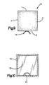
- FIG. 9 illustrates an alternative embodiment of the present invention, whereby a heat-deformable trough-shaped conduit 14 is adhesively or mechanically attached to the side 3 of foam block 11.
- Trough-shaped conduit 14 may also be held on with a strap (not shown).
- trough-shaped conduit 14 defines a passageway between the ends of the foam block 11.
- FIG. 10 illustrates the barrier of FIG. 9 coated with coating 15 and mounted in a hollow channel 19.
- the heat-deformable trough-shaped conduit 14 and the foam block 11 may be separately assembled inside the channel 19, to form the arrangement illustrated in FIG. 10.
- the components of the barrier i.e., the foam block and conduit, need not be attached to each other prior to being mounted in the channel. They may be separately assembled or separately mounted in the channel.
- FIGS. 9 and 10 An advantage of the embodiment of FIGS. 9 and 10 is that the passageway defined by the trough-shaped conduit 14 abuts the bottom inside surface of the channel 19. With this arrangement, the passageway can be placed at the lowest point in the barrier and efficient drainage can be obtained without liquid collecting on a lip.
Landscapes
- Physics & Mathematics (AREA)
- Acoustics & Sound (AREA)
- Engineering & Computer Science (AREA)
- Mechanical Engineering (AREA)
- Body Structure For Vehicles (AREA)
Applications Claiming Priority (2)
| Application Number | Priority Date | Filing Date | Title |
|---|---|---|---|
| US494973 | 1990-03-16 | ||
| US07/494,973 US4989913A (en) | 1990-03-16 | 1990-03-16 | Barrier for use in hollow channel in motor vehicle body and method for producing same |
Publications (1)
| Publication Number | Publication Date |
|---|---|
| EP0447939A1 true EP0447939A1 (fr) | 1991-09-25 |
Family
ID=23966713
Family Applications (1)
| Application Number | Title | Priority Date | Filing Date |
|---|---|---|---|
| EP91103847A Withdrawn EP0447939A1 (fr) | 1990-03-16 | 1991-03-13 | Bouchon pour utilisation dans les cavités du chassis d'un véhicule automobile et son procédé de fabrication |
Country Status (4)
| Country | Link |
|---|---|
| US (1) | US4989913A (fr) |
| EP (1) | EP0447939A1 (fr) |
| JP (1) | JPH05345578A (fr) |
| CA (1) | CA2038173A1 (fr) |
Cited By (2)
| Publication number | Priority date | Publication date | Assignee | Title |
|---|---|---|---|---|
| WO1993011001A1 (fr) * | 1991-12-03 | 1993-06-10 | Stankiewicz Gmbh | Corps de remplissage en forme de piece moulee pour l'obturation de cavites difficilement accessibles |
| EP1591224A1 (fr) * | 2004-04-27 | 2005-11-02 | Sika Technology AG | Dispositif et procédé d'amortissement du son dans espaces creux de véhicules |
Families Citing this family (28)
| Publication number | Priority date | Publication date | Assignee | Title |
|---|---|---|---|---|
| US5213391A (en) * | 1990-10-25 | 1993-05-25 | Nissan Motor Co., Ltd. | Body skeleton element of vehicle and manufacturing method thereof |
| JP2721327B2 (ja) * | 1995-02-09 | 1998-03-04 | 株式会社ネオックスラボ | 中空構造物における発泡性材料の支持構造 |
| JP3376180B2 (ja) * | 1995-08-08 | 2003-02-10 | 株式会社ネオックスラボ | 中空構造物における塗料導入用貫通孔の塞ぎ方法と、その塞ぎキャップ |
| DE19648164C2 (de) * | 1996-11-21 | 2000-01-27 | Karmann Gmbh W | Karosserieteil, insbesondere Profilrahmenträger |
| AUPO379496A0 (en) * | 1996-11-22 | 1996-12-19 | Dominion Plastic Industries | A process for coating foam |
| US5979902A (en) * | 1997-02-24 | 1999-11-09 | Raychem Corporation | Cavity sealing article and method |
| US5931474A (en) * | 1997-02-24 | 1999-08-03 | Raychem Corporation | Cavity sealing article and method |
| EP0961715A1 (fr) | 1997-02-24 | 1999-12-08 | Raychem Corporation | Article et procede permettant de fermer une cavite |
| US6103341A (en) | 1997-12-08 | 2000-08-15 | L&L Products | Self-sealing partition |
| US6114004A (en) * | 1998-01-26 | 2000-09-05 | Cydzik; Edward A. | Cavity sealing article |
| US6093358A (en) * | 1998-01-27 | 2000-07-25 | Lear Corporation | Method of making an expandable gap filling product |
| US6079180A (en) * | 1998-05-22 | 2000-06-27 | Henkel Corporation | Laminate bulkhead with flared edges |
| US6131897A (en) | 1999-03-16 | 2000-10-17 | L & L Products, Inc. | Structural reinforcements |
| US6358584B1 (en) | 1999-10-27 | 2002-03-19 | L&L Products | Tube reinforcement with deflecting wings and structural foam |
| US6668457B1 (en) * | 1999-12-10 | 2003-12-30 | L&L Products, Inc. | Heat-activated structural foam reinforced hydroform |
| US6467834B1 (en) | 2000-02-11 | 2002-10-22 | L&L Products | Structural reinforcement system for automotive vehicles |
| CA2399457C (fr) * | 2000-02-11 | 2009-09-15 | L&L Products, Inc. | Systeme de renfort structurel pour vehicules automobiles |
| US6296298B1 (en) | 2000-03-14 | 2001-10-02 | L&L Products, Inc. | Structural reinforcement member for wheel well |
| US6422575B1 (en) | 2000-03-14 | 2002-07-23 | L&L Products, Inc. | Expandable pre-formed plug |
| US6482486B1 (en) * | 2000-03-14 | 2002-11-19 | L&L Products | Heat activated reinforcing sleeve |
| US6321793B1 (en) | 2000-06-12 | 2001-11-27 | L&L Products | Bladder system for reinforcing a portion of a longitudinal structure |
| US6820923B1 (en) | 2000-08-03 | 2004-11-23 | L&L Products | Sound absorption system for automotive vehicles |
| US6561571B1 (en) | 2000-09-29 | 2003-05-13 | L&L Products, Inc. | Structurally enhanced attachment of a reinforcing member |
| US6471285B1 (en) | 2000-09-29 | 2002-10-29 | L&L Products, Inc. | Hydroform structural reinforcement system |
| DE20200835U1 (de) * | 2002-01-21 | 2003-06-05 | Lear Corp. GmbH & Co. KG, 85560 Ebersberg | Innenverkleidungsteil |
| GB2490707B (en) * | 2011-05-11 | 2013-12-18 | Land Rover Uk Ltd | Assembly and method of manufacture thereof |
| CN103717484B (zh) * | 2011-08-01 | 2016-04-06 | 马自达汽车株式会社 | 车辆的隔音结构 |
| DE102016216028B3 (de) * | 2016-08-25 | 2017-07-06 | Ford Global Technologies, Llc | Verfahren zur Herstellung eines Verbundrohres für eine Kraftfahrzeugkarosserie sowie Verbundrohr und Kraftfahrzeug |
Citations (8)
| Publication number | Priority date | Publication date | Assignee | Title |
|---|---|---|---|---|
| US3678634A (en) * | 1970-08-04 | 1972-07-25 | Sloane Mfg Co R & G | Fire isolation and insulating apparatus |
| US3955594A (en) * | 1974-02-25 | 1976-05-11 | Raymond International Inc. | Pressure operated valve systems |
| FR2396648A1 (fr) * | 1977-07-05 | 1979-02-02 | Teroson Gmbh | Bande de materiau cellulaire, notamment pour l'amortissement de vibrations |
| US4229341A (en) * | 1979-02-15 | 1980-10-21 | Toho Gasu Kabushiki Kaisha | Method of making thermally expansible rubber tubes for use in self-closing gas pipes and pipe joints |
| JPS58139878A (ja) * | 1982-02-16 | 1983-08-19 | Toyota Motor Corp | 車体閉断面の閉塞方法 |
| DE3842890A1 (de) * | 1987-12-21 | 1989-06-29 | Toyota Motor Co Ltd | Waermehaertbares, geschaeumtes dichtungsmaterial |
| JPH01166939A (ja) * | 1987-12-23 | 1989-06-30 | Toyota Motor Corp | 熱硬化型発泡シール材 |
| EP0341330A1 (fr) * | 1988-05-11 | 1989-11-15 | Essex Composite Systems | Pièce d'insertion pour le renfort d'un élément de structure et procédé pour sa fabrication et son utilisation |
Family Cites Families (5)
| Publication number | Priority date | Publication date | Assignee | Title |
|---|---|---|---|---|
| DE2526325A1 (de) * | 1975-06-12 | 1976-12-16 | Daimler Benz Ag | Mehrschichtige schall- und schwingungsdaempfende verkleidung fuer karosserieteile |
| IE47486B1 (en) * | 1977-11-21 | 1984-04-04 | Freight Bonallack Ltd | Structural members for insulated vehicle bodies |
| US4863771A (en) * | 1985-08-22 | 1989-09-05 | The Budd Company | Hollow fiber reinforced structure and method of making same |
| US4741945A (en) * | 1986-07-30 | 1988-05-03 | Arco Chemical Company | Automotive trim panel |
| US4826238A (en) * | 1986-12-01 | 1989-05-02 | Honda Giken Kogyo Kabushiki Kaisha | Side sill for automotive vehicle |
-
1990
- 1990-03-16 US US07/494,973 patent/US4989913A/en not_active Expired - Fee Related
-
1991
- 1991-03-13 EP EP91103847A patent/EP0447939A1/fr not_active Withdrawn
- 1991-03-13 CA CA002038173A patent/CA2038173A1/fr not_active Abandoned
- 1991-03-15 JP JP3074240A patent/JPH05345578A/ja active Pending
Patent Citations (8)
| Publication number | Priority date | Publication date | Assignee | Title |
|---|---|---|---|---|
| US3678634A (en) * | 1970-08-04 | 1972-07-25 | Sloane Mfg Co R & G | Fire isolation and insulating apparatus |
| US3955594A (en) * | 1974-02-25 | 1976-05-11 | Raymond International Inc. | Pressure operated valve systems |
| FR2396648A1 (fr) * | 1977-07-05 | 1979-02-02 | Teroson Gmbh | Bande de materiau cellulaire, notamment pour l'amortissement de vibrations |
| US4229341A (en) * | 1979-02-15 | 1980-10-21 | Toho Gasu Kabushiki Kaisha | Method of making thermally expansible rubber tubes for use in self-closing gas pipes and pipe joints |
| JPS58139878A (ja) * | 1982-02-16 | 1983-08-19 | Toyota Motor Corp | 車体閉断面の閉塞方法 |
| DE3842890A1 (de) * | 1987-12-21 | 1989-06-29 | Toyota Motor Co Ltd | Waermehaertbares, geschaeumtes dichtungsmaterial |
| JPH01166939A (ja) * | 1987-12-23 | 1989-06-30 | Toyota Motor Corp | 熱硬化型発泡シール材 |
| EP0341330A1 (fr) * | 1988-05-11 | 1989-11-15 | Essex Composite Systems | Pièce d'insertion pour le renfort d'un élément de structure et procédé pour sa fabrication et son utilisation |
Non-Patent Citations (2)
| Title |
|---|
| PATENT ABSTRACTS OF JAPAN vol. 13, no. 434 (M-875)(3782) 28 September 1989, & JP-A-01 166939 (TOYOTA MOTOR CORP) 30 June 1989, * |
| PATENT ABSTRACTS OF JAPAN vol. 7, no. 257 (M-256)(1402) 16 November 1983, & JP-A-58 139878 (TOYOTA JIDOSHA KOGYO K.K.) 19 August 1983, * |
Cited By (5)
| Publication number | Priority date | Publication date | Assignee | Title |
|---|---|---|---|---|
| WO1993011001A1 (fr) * | 1991-12-03 | 1993-06-10 | Stankiewicz Gmbh | Corps de remplissage en forme de piece moulee pour l'obturation de cavites difficilement accessibles |
| US5529824A (en) * | 1991-12-03 | 1996-06-25 | Stankiewicz Gmbh | Filler body as molded part for sealing poorly accessible hollow spaces |
| EP1591224A1 (fr) * | 2004-04-27 | 2005-11-02 | Sika Technology AG | Dispositif et procédé d'amortissement du son dans espaces creux de véhicules |
| WO2005105405A1 (fr) * | 2004-04-27 | 2005-11-10 | Sika Technology Ag | Dispositif d'attenuation et procede pour attenuer les sons dans des les habitacles de vehicules |
| US8028799B2 (en) | 2004-04-27 | 2011-10-04 | Sika Technology Ag | Damping device and method for damping sound in cavities of vehicles |
Also Published As
| Publication number | Publication date |
|---|---|
| US4989913A (en) | 1991-02-05 |
| CA2038173A1 (fr) | 1991-09-17 |
| JPH05345578A (ja) | 1993-12-27 |
Similar Documents
| Publication | Publication Date | Title |
|---|---|---|
| US4989913A (en) | Barrier for use in hollow channel in motor vehicle body and method for producing same | |
| DE60036572T2 (de) | Wärmedämmendes Mauerelement und Verfahren zu dessen Herstellung | |
| US20090001758A1 (en) | Expandable insert for hollow structure | |
| ES2284669T3 (es) | Sistema de absorcion de sonido para vehiculos automoviles. | |
| US4391384A (en) | Automobile body panel hole closure | |
| DE3220023C2 (de) | Schalldämpfender Strömungskanal und Verfahren zu seiner Herstellung | |
| US6676195B1 (en) | Self-sealing door water shield barrier | |
| EP1362769A1 (fr) | Obturateurs coniques et expansibles | |
| US5649400A (en) | Support structure for supporting foamable material on hollow structural member | |
| MXPA02009015A (es) | Deflector acustico de doble pared. | |
| EP0200877B1 (fr) | Emballage pour liquides ainsi que procédé et dispositif pour sa fabrication | |
| WO1997049598A1 (fr) | Ensemble d'ecoulement pour systeme acoustique a chicanes | |
| DE2046013C3 (de) | Verfahren zum Auskleiden von Me tallkorpern mit einer Folie aus thermo plastischem Kunststoff | |
| DE19538844A1 (de) | Karosserie-Seitenteil für ein Kraftfahrzeug | |
| EP1742784A1 (fr) | Dispositif d'attenuation et procede pour attenuer les sons dans des les habitacles de vehicules | |
| US20060124386A1 (en) | Acoustic drain | |
| EP0037587B1 (fr) | Structure de longerons pour véhicules | |
| DE59408888D1 (de) | Verfahren zur herstellung einer fliessmittelverpackung und werkzeug zur durchführung des verfahrens | |
| US5089311A (en) | Open faced sandwich barrier | |
| DE102017113355B4 (de) | Verfahren zum Herstellen eines Defrostkanals und Defrostkanal | |
| DE19930900A1 (de) | Dichtung | |
| DE3233106C2 (de) | Verfahren zum Herstellen eines Dosendeckels | |
| JPH03208777A (ja) | 自動車の車体骨格部材とその製造方法 | |
| DE3911741C2 (de) | Kühlgerät | |
| US3209440A (en) | Method of bonding heat exchanger having nested conduit sections |
Legal Events
| Date | Code | Title | Description |
|---|---|---|---|
| PUAI | Public reference made under article 153(3) epc to a published international application that has entered the european phase |
Free format text: ORIGINAL CODE: 0009012 |
|
| AK | Designated contracting states |
Kind code of ref document: A1 Designated state(s): DE FR GB IT SE |
|
| STAA | Information on the status of an ep patent application or granted ep patent |
Free format text: STATUS: THE APPLICATION IS DEEMED TO BE WITHDRAWN |
|
| 18D | Application deemed to be withdrawn |
Effective date: 19920326 |