EP0447514B1 - Circuit de mesure de temperature - Google Patents
Circuit de mesure de temperature Download PDFInfo
- Publication number
- EP0447514B1 EP0447514B1 EP90914502A EP90914502A EP0447514B1 EP 0447514 B1 EP0447514 B1 EP 0447514B1 EP 90914502 A EP90914502 A EP 90914502A EP 90914502 A EP90914502 A EP 90914502A EP 0447514 B1 EP0447514 B1 EP 0447514B1
- Authority
- EP
- European Patent Office
- Prior art keywords
- voltage
- temperature
- terminals
- current
- measuring
- Prior art date
- Legal status (The legal status is an assumption and is not a legal conclusion. Google has not performed a legal analysis and makes no representation as to the accuracy of the status listed.)
- Expired - Lifetime
Links
- 238000009529 body temperature measurement Methods 0.000 title abstract description 6
- 239000004020 conductor Substances 0.000 claims abstract description 65
- 238000010079 rubber tapping Methods 0.000 claims abstract description 22
- 230000001419 dependent effect Effects 0.000 claims abstract description 12
- 238000011156 evaluation Methods 0.000 abstract description 24
- 238000005259 measurement Methods 0.000 description 14
- 230000007704 transition Effects 0.000 description 4
- 238000000034 method Methods 0.000 description 3
- BASFCYQUMIYNBI-UHFFFAOYSA-N platinum Chemical compound [Pt] BASFCYQUMIYNBI-UHFFFAOYSA-N 0.000 description 2
- 230000008569 process Effects 0.000 description 2
- 230000008859 change Effects 0.000 description 1
- 238000001514 detection method Methods 0.000 description 1
- 238000011161 development Methods 0.000 description 1
- 230000018109 developmental process Effects 0.000 description 1
- 230000001771 impaired effect Effects 0.000 description 1
- 229910052697 platinum Inorganic materials 0.000 description 1
- 230000009467 reduction Effects 0.000 description 1
Images
Classifications
-
- G—PHYSICS
- G01—MEASURING; TESTING
- G01K—MEASURING TEMPERATURE; MEASURING QUANTITY OF HEAT; THERMALLY-SENSITIVE ELEMENTS NOT OTHERWISE PROVIDED FOR
- G01K7/00—Measuring temperature based on the use of electric or magnetic elements directly sensitive to heat ; Power supply therefor, e.g. using thermoelectric elements
- G01K7/16—Measuring temperature based on the use of electric or magnetic elements directly sensitive to heat ; Power supply therefor, e.g. using thermoelectric elements using resistive elements
- G01K7/18—Measuring temperature based on the use of electric or magnetic elements directly sensitive to heat ; Power supply therefor, e.g. using thermoelectric elements using resistive elements the element being a linear resistance, e.g. platinum resistance thermometer
- G01K7/20—Measuring temperature based on the use of electric or magnetic elements directly sensitive to heat ; Power supply therefor, e.g. using thermoelectric elements using resistive elements the element being a linear resistance, e.g. platinum resistance thermometer in a specially-adapted circuit, e.g. bridge circuit
-
- G—PHYSICS
- G01—MEASURING; TESTING
- G01K—MEASURING TEMPERATURE; MEASURING QUANTITY OF HEAT; THERMALLY-SENSITIVE ELEMENTS NOT OTHERWISE PROVIDED FOR
- G01K1/00—Details of thermometers not specially adapted for particular types of thermometer
- G01K1/02—Means for indicating or recording specially adapted for thermometers
- G01K1/026—Means for indicating or recording specially adapted for thermometers arrangements for monitoring a plurality of temperatures, e.g. by multiplexing
Definitions
- the temperature measurement is based on the measurement of the resistance value of the temperature-dependent measuring resistor, the resistance measurement being carried out by current-voltage measurement in a four-wire circuit.
- the use of four-wire technology results in higher measuring accuracy because voltage drops caused by the current flowing through the measuring resistor at supply and transition resistances are not included in the measurement result.
- each temperature sensor is connected to the evaluation circuit by four conductors, so that the number of connecting conductors required is proportional to the number of connection conductors required for a larger number of temperature sensors, such as are often required to detect different temperatures at different points in technical systems or processes Number of temperature sensors increases and often becomes undesirably large.
- EP-A-0 187 317 describes a variant of a measuring arrangement in which resistance transducers are connected in series and with a constant current source.
- the object of the invention is to provide a temperature measuring circuit of the type specified, which, while completely retaining the advantages of four-wire technology, requires a significantly smaller number of connecting conductors between the temperature sensors and the evaluation circuit.
- the temperature measuring circuit As a result of the series connection of the temperature sensors, regardless of their number, only two current conductors are required for the connection to the current source, and the number of voltage conductors required is reduced by the fact that in each case two voltage tap terminals, two of which are connected in series consecutive temperature sensors belong to, are connected to a common voltage conductor instead of two separate voltage conductors.
- the total number of connecting conductors required is therefore only three times greater than the number of temperature sensors, compared to four times the number of temperature sensors in conventional temperature measuring circuits. As a result, the more temperature sensors are available, the greater the savings on connecting conductors.
- each common voltage conductor is not directly connected to the two associated voltage tapping terminals, but rather via resistors, ensures that the voltage measurement is carried out practically with the same accuracy as according to the conventional four-wire technique with separate voltage conductors.
- the temperature sensor 10 contains a temperature-dependent measuring resistor 11 with the resistance value R T.
- Four terminals are attached to the measuring resistor 11, namely two current connecting terminals 12, 13 and two voltage tapping terminals 14, 15, the voltage tapping terminal 14 being electrically between the current connecting terminal 12 and the measuring resistor 11 and the voltage tapping terminal 15 being electrically between the current connecting terminal 13 and the resistor 11.
- Resistance temperature sensors of this type are common known and commercially available. Platinum resistance temperature sensors of the type PT 100, which have a resistance of 100 ⁇ at 0 ° C, are widely used.
- the evaluation circuit 20 also contains a voltage measuring device 22 which is connected to the two voltage tapping terminals 14 and 15 via the conductors 18 and 19.
- the voltage measuring device 22 which is symbolically represented as a voltage meter, measures the voltage U T between the two conductors 18 and 19, which are referred to as voltage conductors.
- the temperature detected by the temperature sensor 10 can then be determined from the resistor R T.
- the resistance measurement is carried out by current-voltage measurement, and the use of four-wire technology results in higher measurement accuracy.
- the voltage between the two conductors 16 and 17 measure then the two voltage conductors 18 and 19 could be omitted, but the measured voltage would not be exactly the same as the voltage across the measuring resistor 11, but it would be about the voltage drops caused by the current I const at the supply and transition resistances, greater.
- the voltage drops at supply and transition resistances caused by the current I const have no influence on the measurement result.
- a temperature sensor In technical systems and processes, it is often necessary to record temperatures at different points using a common evaluation circuit. A temperature sensor must then be arranged at each detection point and connected to the common evaluation circuit by the necessary conductors. When using resistance temperature sensors of the type described above, which are operated in a four-wire circuit, four conductors are required for each temperature sensor, which lead to the evaluation circuit. With n temperature sensors, 4n connecting conductors are required.
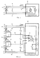
- FIG. 2 shows a temperature measuring circuit with a plurality of resistance temperature sensors of the type described and a common evaluation circuit in which the number of connecting conductors required is significantly reduced.
- the temperature sensor 30 contains one Temperature-dependent measuring resistor 31 of the resistance value R T30 with two current connection terminals 32, 33 and two voltage tapping terminals 34, 35.
- the temperature sensor 40 contains a temperature-dependent measuring resistor 41 of the resistance value R T40 with two current connection terminals 42, 43 and two voltage tapping terminals 44, 45
- the Temperature sensor 50 contains a temperature-dependent measuring resistor 51 of resistance value R T50 with two current connection terminals 52, 53 and two voltage tap terminals 54, 55.
- the evaluation circuit 60 again contains a current source 61, which supplies a constant current I const , and a voltage measuring device 62.
- the temperature sensors 30, 40 and 50 are connected in series via their current connection terminals.
- the current connection terminal 33 of the temperature sensor 30 is connected to the current connection terminal 42 of the temperature sensor 40
- the current connection terminal 43 of the temperature sensor 40 is connected to the current connection terminal 52 of the temperature sensor 50.
- the series connection of the three temperature sensors thus formed is connected to the current source 61 in the evaluation circuit 60 via two current conductors 63 and 64, which are connected to the free current connection terminals 32 and 53 of the temperature sensors 30 and 50, respectively.
- the entire arrangement therefore requires only two current conductors, regardless of the number of temperature sensors, and all measuring resistors 31, 41 and 51 are flowed through in series by the same current I const .
- the outer voltage tap terminal 34 of the temperature sensor 30 is connected to the evaluation circuit 60 via its own voltage conductor 65, and in a corresponding manner the outer voltage tap terminal 55 of the temperature sensor 50 is connected to the evaluation circuit 60 via its own voltage conductor 66.
- the two voltage taps 35 and 44, the interconnected power terminals 33 and 42 of the temperature sensors 30 and 40 are assigned to the evaluation circuit 60 via a common voltage conductor 67, and in a corresponding manner the two voltage terminals 45 and 52, which are assigned to the interconnected current connection terminals of the temperature sensors 40 and 50, are connected to the evaluation circuit 60 via a common voltage conductor 68 .
- the two voltage tapping terminals 35 and 44 are not directly connected to the common voltage conductor 67, but rather are connected via a resistor 70 and 71, respectively.
- the two voltage tapping terminals 45 and 54 are not directly connected to the common voltage conductor 68, but rather are connected via a resistor 72 and 73, respectively.
- a switching device 75 is contained in the evaluation circuit 60, by means of which the voltage measuring device 62 is optionally provided with a pair of the voltage conductors 65 , 66, 67, 68 can be connected.
- the switching device 75 is represented by mechanically adjustable switching contacts, but in reality it is of course formed from electronic switching elements, preferably in the form of a commercially available integrated circuit.
- the switching device 75 connects the voltage measuring device 62 to the two voltage conductors 65 and 67, so that the voltage U T30 is measured between these two conductors.
- the voltage measuring device 62 is connected to the two voltage conductors 67 and 68, so that it measures the voltage U T40 between these two conductors, and when the switching contacts are shifted again by one step the voltage U T50 measured between the two voltage conductors 68 and 66.
- Resistors 70 to 73 ensure that the measured voltages U T30 , U T40 , U T50 correspond with great accuracy to the voltage drops between the voltage tapping terminals of the temperature sensors 30, 40 and 50, respectively. If, for example, the resistors 70 and 71 were not provided and instead the voltage tapping terminals 35 and 44 were directly connected to the common voltage conductor 67, there would be a direct connection between the voltage tapping terminals 35 and 44 in a shunt to the connection between the current connecting terminals 33 and 42 Current I const would then be divided approximately equally between the two parallel connections, and the current component flowing through the shunt would cause voltage drops at contact resistances, which would result in a non-negligible difference between the measured voltage and the actual voltage drop at the measuring resistor.
- the series connection of the resistors 70 and 71 shunts the connection between the current connection terminals 33 and 42.
- the current component flowing through this series connection is so small that the voltage drops it causes at the transition resistances are negligible, provided that the resistance values of the resistors 70 and 71 are large compared to the total resistance of the current path via the current connection terminals 33 and 42.
- the resistance values of the resistors 70 and 71 must be small against the internal resistance of the voltage measuring device 62 so that the voltage drop caused by the measuring current flowing across the voltage conductor 67 across each of these resistors can be neglected compared to the measured voltage.
- the two aforementioned conditions for the dimensioning of the resistors 70 to 73 can easily be met, because the total resistance of the current path via the current connection terminals 33, 42 is in the range of fractions of an ohm, and the internal resistance of the voltage measuring device 62 is in the megohm range. The measurement accuracy is therefore not affected if the resistance value of each of the resistors 70 to 73 is in the order of 100 ⁇ .
- the series connection of the temperature sensors used in the temperature measuring circuit of FIG. 2 offers the possibility of an additional measure by which the current I const is not included in the measurement result, so that the measuring accuracy is not impaired by deviations or fluctuations in the current I const becomes.
- a reference resistor 76 is inserted in the current loop over which the current I const flows, which is a highly constant precision resistor of the value R ref .
- the current I const flowing through the reference resistor 76 generates a voltage drop which can be tapped as a reference voltage U ref between two voltage tap terminals 77 and 78.
- R T30 , R T40 , R T50 of the measuring resistors 31, 41, 51 then result from the ratio of the measured voltages U T30 , U T40 , U T50 to the reference voltage U ref according to the following equations:
- R T30 U T30 U ref .
- R ref R T40 U T40 U ref .
- R ref R T50 U T50 U ref .
- the voltage U ref is continuously available. If it is also queried with the aid of the switching device 75, it must be ensured, however, that the current I const does not change significantly in the time interval between the query of one of the measurement voltages U T30 , U T40 , U T50 and the query of the reference voltage U ref .
- the two resistors 70 and 71 via which the two voltage tapping terminals 35 and 44 are connected to the common voltage conductor 67, have the purpose of avoiding a direct shunt in parallel with the connection via the current connecting terminals 33 and 42. It is not absolutely necessary for this that the two resistors 70 and 71 are present; even if one of the two resistors is omitted and replaced by a direct connection, the other resistor is still shunted to the connection between the power terminals. It is therefore fundamentally possible to connect one of the two voltage terminals 35 or 44 directly to the common voltage conductor 67, provided that a resistor 70 or 71 is inserted in the connection between the other voltage terminal and the common voltage conductor. Of course, this applies correspondingly to the connections between the two voltage tapping terminals 45, 54 and the common voltage conductor 68, where one of the two resistors 72, 73 can likewise be replaced by a direct connection.
Landscapes
- Physics & Mathematics (AREA)
- General Physics & Mathematics (AREA)
- Measuring Temperature Or Quantity Of Heat (AREA)
- Measurement Of Resistance Or Impedance (AREA)
Abstract
Claims (3)
- Circuit de mesure de température à plusieurs capteurs de température dont chacun est constitué d'une résistance de mesure de température dépendant de la température à deux bornes de raccordement d'intensité et de deux prises de tension disposées chacune entre une borne de raccordement d'intensité adjointe et la résistance de mesure dépendant de la température ainsi que d'un circuit d'analyse qui envoie un courant constant à travers chaque capteur de température par les bornes de raccordement d'intensité et qui mesure la chute de potentiel provoquée par le courant constant entre deux conducteurs de tension raccordés par les prises de tension, les capteurs de température étant montés en série par les bornes de raccordement d'intensité, caractérisé par le fait que les deux prises de tension de deux capteurs successifs du montage en série, qui sont adjoints à deux bornes de raccordement d'intensité reliées entre elles, sont raccordées par un fil de tension commun et qu'une résistance est insérée dans la liaison entre au moins l'une des deux prises de tension et le conducteur de tension commun.
- Circuit de mesure de température selon la revendication 1, caractérisé par le fait qu'une résistance de référence constante de grandeur connue est montée en série avec les capteurs de température, de sorte qu'elle est traversée par le courant constant et que la chute de potentiel provoquée par le courant constant sur la résistance de référence sert de tension de référence pour déterminer la valeur de résistance de chaque résistance de mesure.
- Circuit de mesure de température selon les revendications 1 ou 2, caractérisé par le fait que le circuit d'analyse contient un dispositif de mesure de tension et un dispositif de commutation pour relier chaque fois le dispositif de mesure de tension à deux conducteurs de tension reliés au même capteur thermique.
Applications Claiming Priority (2)
| Application Number | Priority Date | Filing Date | Title |
|---|---|---|---|
| DE3933311 | 1989-10-05 | ||
| DE3933311A DE3933311A1 (de) | 1989-10-05 | 1989-10-05 | Temperaturmessschaltung |
Publications (2)
| Publication Number | Publication Date |
|---|---|
| EP0447514A1 EP0447514A1 (fr) | 1991-09-25 |
| EP0447514B1 true EP0447514B1 (fr) | 1993-09-22 |
Family
ID=6390902
Family Applications (1)
| Application Number | Title | Priority Date | Filing Date |
|---|---|---|---|
| EP90914502A Expired - Lifetime EP0447514B1 (fr) | 1989-10-05 | 1990-10-05 | Circuit de mesure de temperature |
Country Status (5)
| Country | Link |
|---|---|
| US (1) | US5171091A (fr) |
| EP (1) | EP0447514B1 (fr) |
| JP (1) | JPH03504048A (fr) |
| DE (2) | DE3933311A1 (fr) |
| WO (1) | WO1991005229A1 (fr) |
Cited By (1)
| Publication number | Priority date | Publication date | Assignee | Title |
|---|---|---|---|---|
| DE4445243A1 (de) * | 1993-12-27 | 1995-06-29 | Ngk Insulators Ltd | Temperaturfühler |
Families Citing this family (23)
| Publication number | Priority date | Publication date | Assignee | Title |
|---|---|---|---|---|
| US5317520A (en) * | 1991-07-01 | 1994-05-31 | Moore Industries International Inc. | Computerized remote resistance measurement system with fault detection |
| AT397311B (de) * | 1991-08-16 | 1994-03-25 | Hans Dr Leopold | Verfahren zur bestimmung einer messgrösse sowie schaltungsanordnung zur durchführung des verfahrens |
| US5435308A (en) * | 1992-07-16 | 1995-07-25 | Abbott Laboratories | Multi-purpose multi-parameter cardiac catheter |
| EP0622733B1 (fr) * | 1993-04-30 | 1997-07-16 | STMicroelectronics S.r.l. | Procédé et dispositif pour tester des dispositifs intégrés de puissance |
| DE4411428A1 (de) * | 1994-03-31 | 1995-10-05 | Bayerische Motoren Werke Ag | Vorrichtung zur Messung zweier physikalischer Parameter |
| DE4442457A1 (de) * | 1994-11-29 | 1996-05-30 | Bayerische Motoren Werke Ag | Temperaturmeßvorrichtung |
| US5775809A (en) * | 1996-07-11 | 1998-07-07 | Measurement Dynamics Llc | Vehicle compartment temperature recorder |
| US5902044A (en) * | 1997-06-27 | 1999-05-11 | International Business Machines Corporation | Integrated hot spot detector for design, analysis, and control |
| US5929344A (en) * | 1997-07-28 | 1999-07-27 | Micro Motion, Inc. | Circuitry for reducing the number of conductors for multiple resistive sensors on a coriolis effect mass flowmeter |
| US6651020B2 (en) * | 1997-12-24 | 2003-11-18 | Edward S. More | Method and apparatus for economical drift compensation in high resolution measurements |
| US6334093B1 (en) * | 1997-12-24 | 2001-12-25 | Edward S. More | Method and apparatus for economical drift compensation in high resolution difference measurements and exemplary low cost, high resolution differential digital thermometer |
| US6786639B2 (en) * | 2002-08-30 | 2004-09-07 | International Business Machines Corporation | Device for sensing temperature of an electronic chip |
| DE102004009267B3 (de) * | 2004-02-26 | 2005-09-22 | Siemens Ag | Ausleseeinrichtung wenigstens eines magnetoresistiven Elementes |
| DE102005029045A1 (de) * | 2005-06-21 | 2007-01-04 | Endress + Hauser Wetzer Gmbh + Co Kg | Vorrichtung und Verfahren zur Bestimmung und/oder Überwachung der Temperatur |
| US7412347B2 (en) * | 2006-01-23 | 2008-08-12 | Sherwood Engineering Design Services, Inc. | Method and apparatus for measuring physical parameters |
| US7896545B2 (en) * | 2008-03-19 | 2011-03-01 | Micron Technology, Inc. | Apparatus and methods for temperature calibration and sensing |
| US8408787B2 (en) * | 2009-01-09 | 2013-04-02 | Rosemount Inc. | Process temperature transmitter with improved temperature calculation |
| DE102012208125A1 (de) * | 2012-05-15 | 2013-11-21 | E.G.O. Elektro-Gerätebau GmbH | Temperaturmesseinrichtung, elektrisches Gerät mit einer solchen Temperaturmesseinrichtung und Verfahren zur Temperaturmessung |
| CN103033278B (zh) * | 2012-12-26 | 2015-07-29 | 重庆川仪自动化股份有限公司 | 一体化温度变送器 |
| DE102013211058B3 (de) * | 2013-06-13 | 2014-10-23 | Lisa Dräxlmaier GmbH | Stromkontaktzange für eine Vier-Leiter-Messung im Bereich Hochvolt und Hochstrom |
| US10591531B2 (en) * | 2015-06-10 | 2020-03-17 | Qualcomm Incorporated | Method and apparatus for integrated circuit monitoring and prevention of electromigration failure |
| US20180254644A1 (en) * | 2017-03-06 | 2018-09-06 | Intel Corporation | Techniques for charger control |
| DE102017130135A1 (de) | 2017-12-15 | 2019-06-19 | Endress + Hauser Wetzer Gmbh + Co. Kg | Zustandsüberwachung eines Temperatursensors |
Family Cites Families (10)
| Publication number | Priority date | Publication date | Assignee | Title |
|---|---|---|---|---|
| JPS526677B1 (fr) * | 1969-10-01 | 1977-02-23 | ||
| DE2526027A1 (de) * | 1975-06-11 | 1976-12-23 | Hartmann & Braun Ag | Schaltungsanordnung zur messung kleiner temperaturdifferenzen |
| DD206176A3 (de) * | 1981-04-22 | 1984-01-18 | Verfahren und schaltungsanordnung zur temperaturmessung | |
| JPS58429A (ja) * | 1981-06-20 | 1983-01-05 | Kyokuto Kaihatsu Kogyo Co Ltd | 三転ダンプトラツク |
| EP0120102A1 (fr) * | 1983-03-23 | 1984-10-03 | Firma Carl Zeiss | Dispositif de mesure de température |
| DE3572861D1 (en) * | 1985-01-03 | 1989-10-12 | Siemens Ag | Measuring equipment with resistance measurement transducer |
| JPS61223622A (ja) * | 1985-03-29 | 1986-10-04 | Toshiba Corp | 多温度計測装置 |
| US4699519A (en) * | 1985-04-08 | 1987-10-13 | Performance Technology, Inc. | Grain temperature monitor |
| SU1352243A1 (ru) * | 1985-12-02 | 1987-11-15 | Предприятие П/Я А-7445 | Многоканальное устройство дл измерени температуры |
| DE3701082A1 (de) * | 1987-01-16 | 1988-07-28 | Ziegler Horst | Einrichtung zur fernmessung der temperatur |
-
1989
- 1989-10-05 DE DE3933311A patent/DE3933311A1/de active Granted
-
1990
- 1990-10-05 WO PCT/DE1990/000762 patent/WO1991005229A1/fr not_active Ceased
- 1990-10-05 EP EP90914502A patent/EP0447514B1/fr not_active Expired - Lifetime
- 1990-10-05 JP JP2513533A patent/JPH03504048A/ja active Pending
- 1990-10-05 DE DE90914502T patent/DE59002854D1/de not_active Expired - Fee Related
- 1990-10-05 US US07/687,863 patent/US5171091A/en not_active Expired - Fee Related
Cited By (3)
| Publication number | Priority date | Publication date | Assignee | Title |
|---|---|---|---|---|
| DE4445243A1 (de) * | 1993-12-27 | 1995-06-29 | Ngk Insulators Ltd | Temperaturfühler |
| US5823680A (en) * | 1993-12-27 | 1998-10-20 | Ngk Insulators, Ltd. | Temperature sensor |
| DE4445243C2 (de) * | 1993-12-27 | 2002-03-21 | Ngk Insulators Ltd | Temperaturfühler |
Also Published As
| Publication number | Publication date |
|---|---|
| EP0447514A1 (fr) | 1991-09-25 |
| DE3933311A1 (de) | 1991-04-18 |
| US5171091A (en) | 1992-12-15 |
| DE59002854D1 (de) | 1993-10-28 |
| JPH03504048A (ja) | 1991-09-05 |
| DE3933311C2 (fr) | 1992-03-26 |
| WO1991005229A1 (fr) | 1991-04-18 |
Similar Documents
| Publication | Publication Date | Title |
|---|---|---|
| EP0447514B1 (fr) | Circuit de mesure de temperature | |
| EP2981833B1 (fr) | Résistance de mesure et procédé de mesure correspondant | |
| EP2880410B1 (fr) | Système de mesure à plusieurs fils servant à détecter un capteur de résistance dépendant de la température défaillant | |
| DE102004056133B4 (de) | Verfahren zur Erfassung einer Offsetdrift bei einer Wheatstone-Meßbrücke | |
| EP1431768B1 (fr) | Procédé et dispositif de mesure de la résistivité d'un élément de résistance sensible à la température | |
| EP0203350A2 (fr) | Dispositif de mesure de la température pour mesurer de grands changements en température | |
| EP0612412B1 (fr) | Procede et dispositif pour les tests de polarite de condensateurs electrolytiques | |
| EP0016409B1 (fr) | Appareil de mesure de la température et de la différence de température pratiquement simultanée | |
| DE2531784C2 (de) | Meßanordnung zur Temperatur- und Druckmessung eines Mediums in Bohrlöchern | |
| WO2004106866A2 (fr) | Procede et montage pour detecter un niveau de remplissage de liquide | |
| DE19531386C2 (de) | Auswerteschaltung für einen Dickfilm-Drucksensor | |
| DE3344363C2 (fr) | ||
| DE2141361B2 (fr) | ||
| DE3634053A1 (de) | Verfahren und schaltungsanordnung zur messung der widerstandswerte zweier in reihe geschalteter sensorwiderstaende | |
| DE4040332C2 (de) | Mehrelektroden-Streufeldverfahren zur Messung der elektrolytischen Leitfähigkeit einer Flüssigkeit sowie Mehrelektroden-Streufeldsensor dazu | |
| EP1962070B1 (fr) | Capteur haute température et procédé pour sa vérification | |
| DE2162040C3 (de) | Schaltungsanordnung zum Erfassen von Leitungskurzschlussen | |
| DE3731012C2 (de) | Zündkreisprüfer mit klimakonstanter Anzeige | |
| DE2318520C2 (de) | Schaltungsanordnung mit einem Widerstand smeBwertgeber | |
| EP1870701B1 (fr) | Agencement destiné à la détection de substances dans l'air | |
| DE1103458B (de) | Direkt anzeigendes Ohmmeter mit umschaltbaren Messbereichen | |
| EP0877238A1 (fr) | Dispositif de mesure avec plusieurs canaux d'entrée | |
| DE3032948A1 (de) | Widerstandsmessgeraet | |
| DE1113748B (de) | Direkt anzeigendes Ohmmeter | |
| DE4428689A1 (de) | Verfahren und Anordnung zum Betreiben einer Vierleiter-Schaltung für Widerstandsthermometer |
Legal Events
| Date | Code | Title | Description |
|---|---|---|---|
| PUAI | Public reference made under article 153(3) epc to a published international application that has entered the european phase |
Free format text: ORIGINAL CODE: 0009012 |
|
| 17P | Request for examination filed |
Effective date: 19910524 |
|
| AK | Designated contracting states |
Kind code of ref document: A1 Designated state(s): CH DE FR GB IT LI SE |
|
| 17Q | First examination report despatched |
Effective date: 19930218 |
|
| GRAA | (expected) grant |
Free format text: ORIGINAL CODE: 0009210 |
|
| AK | Designated contracting states |
Kind code of ref document: B1 Designated state(s): CH DE FR GB IT LI SE |
|
| ITF | It: translation for a ep patent filed | ||
| REF | Corresponds to: |
Ref document number: 59002854 Country of ref document: DE Date of ref document: 19931028 |
|
| ET | Fr: translation filed | ||
| GBT | Gb: translation of ep patent filed (gb section 77(6)(a)/1977) |
Effective date: 19940106 |
|
| PLBE | No opposition filed within time limit |
Free format text: ORIGINAL CODE: 0009261 |
|
| STAA | Information on the status of an ep patent application or granted ep patent |
Free format text: STATUS: NO OPPOSITION FILED WITHIN TIME LIMIT |
|
| 26N | No opposition filed | ||
| EAL | Se: european patent in force in sweden |
Ref document number: 90914502.1 |
|
| PGFP | Annual fee paid to national office [announced via postgrant information from national office to epo] |
Ref country code: CH Payment date: 19990915 Year of fee payment: 10 |
|
| PGFP | Annual fee paid to national office [announced via postgrant information from national office to epo] |
Ref country code: SE Payment date: 19990920 Year of fee payment: 10 |
|
| PG25 | Lapsed in a contracting state [announced via postgrant information from national office to epo] |
Ref country code: SE Free format text: THE PATENT HAS BEEN ANNULLED BY A DECISION OF A NATIONAL AUTHORITY Effective date: 20001030 |
|
| PG25 | Lapsed in a contracting state [announced via postgrant information from national office to epo] |
Ref country code: LI Free format text: LAPSE BECAUSE OF NON-PAYMENT OF DUE FEES Effective date: 20001031 Ref country code: CH Free format text: LAPSE BECAUSE OF NON-PAYMENT OF DUE FEES Effective date: 20001031 |
|
| REG | Reference to a national code |
Ref country code: CH Ref legal event code: PL |
|
| EUG | Se: european patent has lapsed |
Ref document number: 90914502.1 |
|
| REG | Reference to a national code |
Ref country code: GB Ref legal event code: IF02 |
|
| PGFP | Annual fee paid to national office [announced via postgrant information from national office to epo] |
Ref country code: GB Payment date: 20030929 Year of fee payment: 14 |
|
| PGFP | Annual fee paid to national office [announced via postgrant information from national office to epo] |
Ref country code: FR Payment date: 20031009 Year of fee payment: 14 |
|
| PGFP | Annual fee paid to national office [announced via postgrant information from national office to epo] |
Ref country code: DE Payment date: 20031010 Year of fee payment: 14 |
|
| PG25 | Lapsed in a contracting state [announced via postgrant information from national office to epo] |
Ref country code: GB Free format text: LAPSE BECAUSE OF NON-PAYMENT OF DUE FEES Effective date: 20041005 |
|
| PG25 | Lapsed in a contracting state [announced via postgrant information from national office to epo] |
Ref country code: DE Free format text: LAPSE BECAUSE OF NON-PAYMENT OF DUE FEES Effective date: 20050503 |
|
| GBPC | Gb: european patent ceased through non-payment of renewal fee |
Effective date: 20041005 |
|
| PG25 | Lapsed in a contracting state [announced via postgrant information from national office to epo] |
Ref country code: FR Free format text: LAPSE BECAUSE OF NON-PAYMENT OF DUE FEES Effective date: 20050630 |
|
| REG | Reference to a national code |
Ref country code: FR Ref legal event code: ST |
|
| PG25 | Lapsed in a contracting state [announced via postgrant information from national office to epo] |
Ref country code: IT Free format text: LAPSE BECAUSE OF NON-PAYMENT OF DUE FEES;WARNING: LAPSES OF ITALIAN PATENTS WITH EFFECTIVE DATE BEFORE 2007 MAY HAVE OCCURRED AT ANY TIME BEFORE 2007. THE CORRECT EFFECTIVE DATE MAY BE DIFFERENT FROM THE ONE RECORDED. Effective date: 20051005 |